1
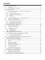
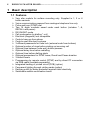
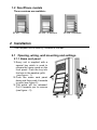
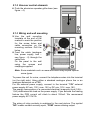
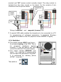
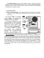
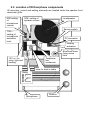
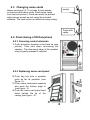
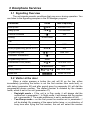
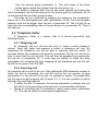
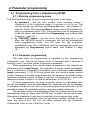
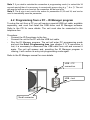
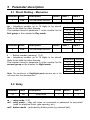
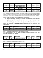
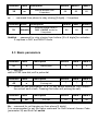
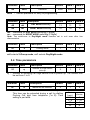
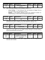
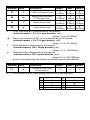
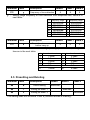
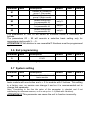
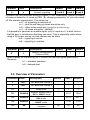
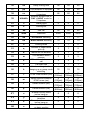
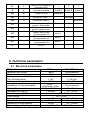
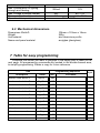
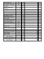
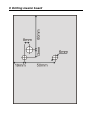
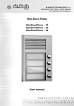
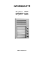
INTERQUARTZ Doorphone – ID 201 Doorphone – ID 202 Doorphone – ID 204 User manual Contents 1 2 3 4 5 6 7 BASIC DESCRIPTION....................................................................................... 3 1.1 FEATURES ...................................................................................................... 3 1.2 SLIMDOORPHONE MODELS ............................................................................ 4 INSTALLATION ................................................................................................. 4 2.1 OPENING, WIRING, WALL MOUNTING AND SETTINGS ...................................... 4 2.1.1 Name card panel....................................................................................... 4 2.1.2 Uncover control elements ......................................................................... 5 2.1.3 Wiring and wall mounting ........................................................................ 5 2.1.4 Switches .................................................................................................... 6 2.1.5 Voice level................................................................................................. 7 2.2 LOCATION OF ID DOORPHONE COMPONENTS ................................................. 8 2.3 CHANGING NAME CARDS................................................................................ 9 2.4 FINAL CLOSING OF ID DOORPHONE ............................................................... 9 2.4.1 Covering control elements ........................................................................ 9 2.4.2 Replacing name card panel ...................................................................... 9 SLIMDOORPHONE SERVICES .................................................................... 10 3.1 SIGNALLING OVERVIEW............................................................................... 10 3.2 VISITOR AT THE DOOR .................................................................................. 10 3.3 TELEPHONE CALLER .................................................................................... 11 3.3.1 Outgoing call .......................................................................................... 11 3.3.2 Incoming call .......................................................................................... 11 PARAMETER PROGRAMMING................................................................... 12 4.1 PROGRAMMING FROM A TELEPHONE BY DTMF........................................... 12 4.1.1 Entering programming mode.................................................................. 12 4.1.2 Parameter programming ........................................................................ 12 4.2 PROGRAMMING FROM A PC – ID MANAGER PROGRAM................................ 13 PARAMETER DESCRIPTION ....................................................................... 14 5.1 DIRECT DIALLING – MEMORIES ................................................................... 14 5.2 RELAY ......................................................................................................... 14 5.3 BASIC PARAMETERS ..................................................................................... 16 5.4 TIME PARAMETERS....................................................................................... 17 5.5 PRESETTING AND DELETING ........................................................................ 20 5.6 EXIT PROGRAMMING .................................................................................... 21 5.7 SYSTEM SETTING.......................................................................................... 21 5.8 OVERVIEW OF PARAMETERS ........................................................................ 22 TECHNICAL PARAMETERS......................................................................... 24 6.1 ELECTRICAL PARAMETERS ........................................................................... 24 6.2 MECHANICAL DIMENSIONS .......................................................................... 25 TABLE FOR EASY PROGRAMMING.......................................................... 25 8 DRILLING MASTER BOARD ........................................................................ 27 1 Basic description 1.1 Features Very slim module for surface mounting only. Supplied in 1, 2 or 4 button variants. Voice communication powered from analogue telephone line only. Pulse and tone (DTMF) dial Two 16 digits numbers saved under each button (includes *, #, RECALL and pause) DAY/NIGHT mode Call prolongation by dialling * or # Electrical (magnetic) lock compatible Code to hang up from phone Code to open the door by phone 3 different passwords for code lock (external code from buttons) Optional number of rings before picking up incoming call Optional time between code entry button-presses Optional delay time before redialling Optional time before dialling starts Optional parameters for DTMF tones, Recall and Pause duration 3 default levels Programming by remote control (DTMF) and by direct PC connection via USB cable (available separately) Integrated heating of printed circuit (PCB) (option) Permanent lighting through visiting cards (option) Earthing outlet for better protection against static electricity Switchable audible confirmation tones 1.2 DoorPhone models Three versions are available : ID 201 -1 button ID 202 - 2 buttons ID 204 -4 buttons 2 Installation This compact unit is fixed by 2 screws to the wall. 2.1 Opening, wiring, wall mounting and settings 2.1.1 Name card panel 1. Every unit is supplied with a special key which is used to release the name cards on the front panel. Push the key into the hole in the speaker grille (see figure - 1). 2. Push the name card panel down and then push it towards to grille (see figure-2). 3. The panel will be released. Pull it towards you to remove (see figure – 3). 2.1.2 Uncover control elements 4. Push the aluminium speaker grille down (see figure – 4). 2.1.3 Wiring and wall mounting 5. Use the wall mounting template at the end of the manual to mark the position for the screw holes and cable connection on the mounting surface. Drill the holes. 6. Feed the cable (analogue line, power supply, lock – see figure - 6) through the cable hole. Fix the panel to the wall using the screws and rawlplugs supplied. Note: Some materials such as metal and wood may require special screw types. To power the unit for voice, connect the telephone wires into the terminal (on the right side). Using either a standard analogue phone line or an analogue extension on a PBX. For the external power supply, connect to the terminal "12V" external power supply AC min. 10V / max. 15V or DC min. 12V / max. 18V. The energy consumption of a connected electrical (magnetic) lock (0,5A – 1,0A) determines the load on the power supply. If you activate the heating feature the PCB current will climb to about 150mA. We recommend power supply AC 12V/1A. The wiring of relay contacts is explained in the next picture. The symbol "NO" means contact normally open, "COM" means sharing output (central) and "NC" means contact normally closed. The relay contact is isolated from the other circuits on the board. For the variants of lock connection see the picture below. Telephone line Power supply lock Wiring of standard and magnetic (inverse) lock 7. A special USB cable enables the doorphone to be connected to a PC for programming of individual parameters. A dedicated Windows program is included on the CD (requires version W98SE or higher). 2.1.4 Switches 8. The switch marked HEAT (see figure – 8) activates heating of the PCB. This is for increased resistance against humidity. To use this feature you must connect an external 12V power supply. 9. The switch marked SERVICE (see figure – 9) is required for programming the unit when the password is forgotten. It is performed by ordinary phone (DTMF – tone dial ). The switch is The PCB heating has two major benefits. Firstly, it warms the board during winter time (temperatures under -20 C, most circuits have warranty operation down to -20 C) and secondly it helps to protect the PCB against humidity when installed outside. 2.1.5 Voice level 10. Voice communication – the trimmer position is factory and should be suitable for most installations. Change the trimmer position only when necessary. The trimmer "MIC" is designed for microphone volume setting. The trimmer "SPK" is designed for loudspeaker volume setting. The volume settings are more than adequate for most situations. Therefore we do not recommend setting the trimmer position more than ½. The most suitable position is 1/3 from minimum amplification. The trimmer "TRH" is designed for setting the microphone activation level. It allows balancing between the microphone and speaker to eliminate feedback. This setting is also influenced by the noise of the surrounding environment. Set up Process: The trimmers MIC and SPK are set to ¼ position from minimum loudness level (turn fully anti-clockwise for minimum). The trimmer TRH is set to a central position. To fine tune, make a test call. Speak quietly, and by adjusting the trimmer TRH from the central position anticlockwise, your speech should be heard more clearly by the PBX user. The amplification of the speaker can be adjusted according to your requirements. Voice interruption might occur if you set the amplification too high. In this case you can use the trimmer TRH to correct the balance between the speaker and the microphone. 2.2 Location of ID Doorphone components All mounting, control and setting elements are located under the speaker front aluminium grille. SPK- setting of speaker volume MIC-setting . of microphone volume Loudspeaker Service switch TRH – setting of microphone activation level PC connector Heating activation SlimDoorPhone fixing screw hole 12V =/~ for relay, light and heating Telephone line connection Hole for lead in cable Relay Microphone Buttons 2.3 Changing name cards Name card panel (2.1.1on page 4) has spaces to insert printed name cards. Insert name cards from top (see picture). Cards can easily be printed with pictures as well as text using the included software. The card outline is marked for easy cutting . pocket Panel with cards 2.4 Final closing of ID Doorphone 2.4.1 Covering control elements 1. Push aluminium speaker cover back up (see picture). Take care when re-covering the speaker. The aluminium edge of the speaker may be gently pressed if required. 2.4.2 Replacing name card panel 2. Push key into hole in speaker grille as far as possible. (see figure -2). 3. Push name card panel upwards and push the bottom edge in (see figure - 3). 4. Push the name card panel back down behind the lip of the casing (see figure - 4). 3 Doorphone Services 3.1 Signalling Overview The unit signals acoustic conditions that may occur during operation. You can listen to the signalling samples in the ID Manager program. Condition Tones Tone frequency Pick up line –▄–■–▀– 425-850-1275 Hang up line –▀–■–▄ 1275-850-425 ––█–– 425 Confirm command Dialling DTMF/Pulse Call Conversation end warning –■–■–■– 1275 Enter programming (phone or PC) –■–■–■– 850 ––▓–▓––––– mod. 850 Programming tone Parameter confirmation ––█–– Programming from PC Silent Connection to line (Reset) –■–▄–■– 1275-850-1275 Error –■–■–■–■–■–■– 425…. Empty memory –█–▄–■–▄–■–▄– 850-1275-1700… ▓▓▓▓▓▓▓ modul 50/1250 Open lock 3.2 Visitor at the door When a visitor presses a button the unit will lift up the line, either immediately (providing the button is not the first number from code lock), or with delay (parameter 53) and after period given by parameter 55, will dial the programmed phone number. The dialled number is dictated by the chosen mode, which is set in the unit (parameter 47): - Day/night mode = If the unit is in Day mode, it will always dial the number set in parameter 1, In Night mode, it will always dial the number set in parameter 2. The mode switchover is set in parameters 45,46. - Two-Group mode = on the first press the number set in parameter 1 will be dialled. By pressing of the same button twice, or on detection of busy tone after trying the first number, the unit will select the number from the second group (parameter 2). The next press of the same button again selects the number from the first group, etc..…… If the button is pressed after the line has been opened (but before the call is answered), the unit will hang up for the period given by parameter 54, lift up the line and dial the other group number. The relay can be controlled by pressing the buttons in the combination that is set in the preprogrammed code (parameters 32-34). The time between presses must not be bigger than that set in parameter 53. The unit will lift up and close the corresponding relay or the period given by parameter 36 . Then it will hang up. 3.3 Telephone Caller A Telephone Caller is a person that is in phone connection with SlimDoorPhone. 3.3.1 Outgoing call An “outgoing” call is a call from the unit (i.e. when a visitor presses a button). Once the visitor has pressed a button a telephone will ring. On answering the telephone, you will be able to converse with the visitor. 10 seconds before the maximum call duration (parameter 52) the unit will emit a tone to warn that the call will end. The call may be extended by pressing the key as set in parameter 42. A code may be dialled to close the relay (parameter 35), releasing the lock. Hanging up the telephone will end the call, as will the busy tone from the PBX. 3.3.2 Incoming call An incoming call is a call to the unit. After dialling the PBX extension number to which the unit is connected, the unit will ring for the set number of rings (parameter 51), the unit will lift up and it is possible to speak. The possibilities are the same as with outgoing call (Chapter 3.3.1). It is also possible to switch between Day and Night service. • If, within the first 10 seconds, the service password is entered, the unit will switch to programming mode and voice communication will cease. • During an incoming call it is possible to restrict relay control (parameter 37). This can be useful in some special applications. 4 Parameter programming 4.1 Programming from a telephone by DTMF 4.1.1 Entering programming mode The SlimDoorPhone may be set to programming mode in two ways: 1. by password – dial the unit‘s number (either extension number, if connected to a PBX or telephone number, if connected to a PSTN line). The unit will answer (you will hear the Pick up line tone – see Chapter 3.1 page10). Within 10 seconds dial #xxxx, where xxxx is the password for entry to programming and, if OK, the registration tone for programming mode will sound, and afterwards the Programming tone is heard (see Chapter 3.1 page 10). 2. by "SERVICE" switch – dial the unit in the same way as in 1, but when the SERVICE switch is connected, the unit will automatically enter programming mode. You will hear the call connection confirmation tone, the confirmation tone for programming mode and afterwards the Programming tone is heard. (see Chapter 3.1 page 10). 4.1.2 Parameter programming The initial state for programming is signalled by the programming confirmation tone. The unit will always revert to this state after 5 seconds of inactivity, even if you have started to program a parameter. When programming, there are two types of parameters. The majority are parameters with a fixed length. The parameter is always saved immediately and is confirmed by Parameter Confirmation tone. Parameters with variable length (parameters 1,2,32,33,34) are saved after the inactivity period expires (5 sec). However, a varaible length parameter will be saved immediately when maximum permitted number of digits is reached. For parameters 1 and 2 the maximum number of digits is 16, and for parameters 32,33,34 it is 6. If, during programming, you enter a number which is not allowable, then the unit immediately emits an error tone. The parameter will not be recorded or changed, and the unit will return to its initial programming state and it will be possible to repeat the parameter setting or program another parameter. The unit stays inactive in programming mode for 34 seconds and will then automatically hang up. Every time a DTMF tone is dialled, this period is reset. Alternatively, parameter 9 may also be selected to end programming mode. To program a parameter, enter the parameter number followed by the value you wish to set. The unit will either respond with the Parameter Confirmation Tone, or one of the Error Tones. Note 1. if you wish to maintain the connection in programming mode (i.e. extend the 34 seconds period) then it is necessary to occasionally press a key (e.g. *, # or 7). The unit will respond with an error tone but the connection will be kept alive. Note 2. The # sign is not used in the values for parameters 32,33 and 34, and can be used to immediately save the parameter. 4.2 Programming from a PC – ID Manager program To setup the unit from a PC you will require a special USB tool cable, available separately, and must first install the USB driver and ID Manager software. Refer to the CD for more details. The unit must also be connected to the telephone line. Procedure: - Connect the ID Doorphone to the line - Connect the unit to the PC with the USB tool cable. - Run the ID Manager program. The unit will enter PC programming mode and emit the Enter Programming tone (see chapter 3.1). If connection is lost, it is necessary to disconnect the USB cable from unit and connect it again. The unit will answer and, providing the ID Manager program is running, it will confirm its entry into programming mode again. Refer to the ID Manager manual for more details. USB – PC connection USB – tool Small connector 5 Parameter description 5.1 Direct Dialling – Memories Parameter Value 1 t nn… Description No. nn under button t Default Exam.1 - - t – Button number (memory) [1-4] nn – telephone number up to 16 digits to be stored. Refer to the table for other choices. The number stored in parameter 1 is the number for the first group or the number for Day mode. Parameter Value 2 t nn… Description No. nn under button t Exam.2 - parameter 0-9 # * Recall Pause Default Exam.1 - - t – Button number (memory) [1-4] nn – telephone number up to 16 digits to be stored. Refer to the table for other choices. The number stored in parameter 2 is the number for the second group or the number for Night mode Note: The switchover to Day/Night mode remains set in the unit even after line disconnection. dial 0-9 # ** *# *0 Exam.2 - parameter choice 0-9 0-9 # # * ** Recall *# Pause *0 5.2 Relay Parameter Value 31 m Description Relay mode Default Exam.1 1 1 Exam.2 2 m – relay mode [ 1-2] m=1 relay mode – relay will close on command or password for ss period (used for electrical locks, gate opening, etc.) m=2 button mode – (activated by button press e.g. external bell). Parameter Value 32 hhhhhh 33 hhhhhh 34 hhhhhh Description External access code in DAY + NIGHT mode External access code in DAY mode External access code in NIGHT mode Default Exam.1 Exam.2 - 1212 1324 - 2211 2211 - 1122 1122 hhhhhh – password for relay closing from buttons [2 to 6 digits] The 3 passwords are controlled by Day/Night; the combination is entered using the unit buttons. It is influenced by the setting of Relay mode and Day/Night switchover. When set to 2-group mode the unit is permanently in DAY mode. Follow these rules when choosing password combination: Select passwords carefully, to prevent their discovery from wear on buttons caused by frequent use. Select the first password button from infrequently-used buttons for direct dialling (-extends choice time)(-not valid for keyboard). Note: The switchover to Day/Night mode remains set in unit even after line disconnection. Parameter Value Description 35 aa Internal access code Default 55 Exam.1 Exam.2 55 55 aa – command from phone to relay closing [2 digits] It is recommended to set the same command for Internal Access Code and End Call (parameter 43) aa=bb. Parameter Value 36 ss Description Relay closing time [sec] Default 05 Exam.1 Exam.2 02 05 ss – duration of relay closing [2 digits 01-99] Parameter Value 37 pp Description Time between 2 impulses [sec] Default 05 Exam.1 Exam.2 05 pp – duration of delay between 2 impulses of relay [2 digits 01-99] 05 Parameter Value Description 38 cc Default Internal access code 2 impulses 66 Exam.1 Exam.2 66 66 cc – command from phone to relay closing [2 digits] – 2 impulses Parameter Value 39 hhhhhh Description External access code in DAY + NIGHT mode for 2 impulses Default Exam.1 66 66 Exam.2 66 hhhhhh – password for relay closing from buttons [2 to 6 digits] for activation 2 impulses in DAY and NIGHT mode. 5.3 Basic parameters Parameter Value 41 v Description Dialling type Default 0 Exam.1 Exam.2 0 0 v – dial type v=0 is DTMF tone dial, v=1 is pulse dial Parameter Value 42 z Description Prolong call Default * Exam.1 Exam.2 * * z – button for call prolongation *or # (10 sec before Maximum Call Duration the unit will emit a tone. Pressing this button will prolong the call) Parameter Value 43 bb Description End call Default 55 Exam.1 Exam.2 55 55 bb – command for unit hanging up from phone [2 digits] It is recommended to set the same command for both Internal Access Code (parameter 35) and End Call aa=bb. Parameter Value 44 Description xxxx Default 0000 Password Exam.1 Exam.2 0000 0000 xxxx – service password for entry to programming Parameter Value Description Default Exam.1 Exam.2 45 dd DAY MODE switching 11 11 11 46 nn NIGHT MODE switching 10 10 10 dd – command for DAY MODE switching [2 digits] nn – command for NIGHT MODE switching [2 digits] Note: The switchover to Day/Night mode remains set in unit even after line disconnection. Parameter Value 47 Description e Dialling mode Default 1 Exam.1 Exam.2 1 0 e – operating mode of unit e=0 selects 2-Group mode, e=1 selects Day/Night mode. 5.4 Time parameters Parameter Value 51 q Description Number of rings before pick-up Default 2 Exam.1 Exam.2 1 2 q – Number of incoming call rings before a call is picked up. The number can be set from 1 to 9. Parameter 52 Value d Description Maximum call duration Default 2 d – maximum time in minutes for which a call may last. This time can be extended during a call by dialling Prolong Call digit from telephone (*or #). Time setting is per table. Exam.1 Exam.2 1 time [min] 0,5 1-9 15 30 4 choice 0 1-9 * # Parameter 53 Value w Description time between button presses Default 2 Exam.1 Exam.2 2 2 w – max. time [sec] between button presses [range 1-9] - relay closing – if time between two next presses is bigger than w time, the code is not evaluated correctly. dialling – if the button pressed is the first password number for switch closing, so the choice is delayed by this w time. Parameter 54 Value z Description Off hook time before new call Default 2 Exam.1 Exam.2 2 2 z – time [sec] for which the unit will hang up, before repeat dialling (button pressing during call or dialling, busy tone detection) [range 1-5] Parameter 55 Value z Description Call start time Default 1 Exam.1 Exam.2 1 1 z – time [sec] after unit goes off hook before dialling [range 1-5]. This time is different for each PBX, but most PBXs usually manage to process dialling up to 2 seconds after line off hook. Parameter Value 56 h Description Number of rings before hanging up or group mode switching Default 12 Exam.1 Exam.2 12 12 h – specifies the amount of time spent ringing before the unit hangs up and tries the next number. Parameter Value Description Default Exam.1 Exam.2 5 5 5 (100ms) (100ms) (100ms) 5 5 5 Space duration between 58 m DTMF tones (ms) (100ms) (100ms) (100ms) 1 1 1 Recall duration (ms) 59 f (100ms) (100ms) (100ms) 8 8 8 Pause duration (ms) 50 p (800ms) (800ms) (800ms) t – DTMF tone duration is determined by the formula: (entered number + 5) x 10 = tone duration [ms] [range 1-0 i.e. 60-150ms] m – Space duration between DTMF tones is determined by the formula: (entered number + 5) x 10 = gap duration [ms] [range 1-0 i.e. 60-150ms] f – Recall duration is determined by the formula: entered number x 100 = Recall duration [ms] [range 1-6 i.e. 100-600ms] p – Pause duration is determined by the formula: entered number x 100 = pause duration [ms] [range 5-0 i.e. 500-1000ms] – p time is simultaneously the duration of interdigit gap at pulse dialling. 57 t Parameter Value 5*1 x DTMF tone duration (ms) Description Default Number of busy tones before hang up 6 Exam.1 Exam.2 6 6 x – is the number of busy tones before hang up, as in the next table: x 1 2 3 4 number of busy tones 4 4 6 6 x 5 6 7 8 number of busy tones 8 8 10 10 Parameter Value 5*2 y Description Default Exam.1 Exam.2 4 Frequency of tone detection 4 4 y – setting range frequency of tone detection from telephone line, value is in next table: y frequency range y frequency range 1 200-350Hz 7 500-650Hz 2 250-400Hz 8 550-700Hz 3 300-450Hz 9 600-750Hz 4 350-500Hz 0 650-800Hz 5 400-550Hz * 700-850Hz 6 450-600Hz # 750-900Hz Parameter Value 5*3 z Description Default Time of continuous tone before hang up Exam.1 Exam.2 0 0 0 z – time of continuous tone before hang up. Hang up on dial tone, setting the time as in the next table: z time of continous tone z time of continous tone 1 1.2sec 7 3.3sec 2 1.6sec 8 3.6sec 3 2.0sec 9 3.9sec 0 4.2sec 4 2.3sec 5 2.6sec * 4.6sec 6 3.0sec # 5.0sec 5.5 Presetting and Deleting Parameter Value Description 8# # Default setting 8# 1 Setting per exam. 1 8# 2 Setting per exam. 2 Default Exam.1 Exam.2 executes executes This setting does not influence 1 and 2 (numbers stored in memory) executes Parameter Value Description Deletes all numbers in group 1 (Day mode) Deletes all numbers in group 2 (Night mode) Default setting only for parameters 3x Default setting only for parameters 4x Default setting only for parameters 5x 81 82 83 84 85 Default Exam.1 Exam.2 only 3.. only 4.. only 5.. The parameters 81 and 82 will delete all numbers stored in memories for buttons. The parameters 83 – 85 will execute a selective basic setting only for parameters starting with 3.. – 5.. ATTENTION !!! the deletion is non-reversible!!! Numbers must be programmed again. 5.6 Exit programming Parameter Value Description 9 Default Exam.1 Exam.2 Default Exam.1 Exam.2 END After dialling 9 the unit will hang up. 5.7 System setting Parameter Value 6# s Description Number of fitted buttons of basic module The basic module is fitted with 4 buttons as standard, i.e. s = 1 is set up for basic module with one button and s = 2 for module with 2 buttons. This setting is a factory one, no service can change it and so it is recommended not to change this parameter. Note: Connecting to the line the value of this parameter is checked and if not satisfactory for unknown reasons, so it is set up to s = 4 (fitted with 4 buttons). ATTENTION !!! This parameter can cause the unit to function incorrectly. Parametr 6 Value z Description Acoustic signalling Default 3 and 9 Exam.1 Exam.2 3 and 9 3 and 9 In default the unit produces acoustic signals. It can occasionally cause a problem of incorrect detection of tones by PBX. By changing parameter „z“ you can switch off this acoustic signalization. The values are: z=0 – all signalling is switched off z=1 – pick up and hang up tones are active only z=2 – other tones active only (except pick up and hang up) z=3 – all tones are active – (default) It is possible to generate an audible signal (only in mode m=1) to alert visitors that the door is unlocked so that they can enter. This is especially useful when using a DC power source, as lock release may be silent. z=8 – signalling is active z=9 – signalling is unactive Parameter Value 6* t Description Default Delay of line connection (Siemens PBX) Exam.1 Exam.2 1 1 1 Setes a delay for line pick-up (OFF HOOK) for new PBX types (particularly Siemens): t=1 – standard operation t=0 – delayed start 5.8 Overview of Parameters Parameter Value Description Default Exam.1 Exam.2 1 t nn… No. nn under button t - - - 2 t nn… No. nn under button t - - - 31 r Relay mode 1 1 2 - 2211 1324 - 2211 2211 - 1122 1122 55 55 55 32 hhhhhh 33 hhhhhh 34 hhhhhh 35 aa External access code in DAY + NIGHT mode External access code in DAY mode External access code in NIGHT mode Internal access code 1 impulse 36 ss Relay closing time 05 02 05 37 pp Time between 2 impulses 05 05 05 38 cc 66 66 66 39 hhhhhh - - - 41 v Dialling type 0 0 0 42 z Prolong call * * * 43 bb End call 55 55 55 44 xxxx Password 0000 0000 0000 45 dd DAY MODE switching 11 11 11 46 nn NIGHT MODE switching 10 10 10 47 e Dialling mode 1 1 0 51 q Number of rings before pick-up 2 1 2 52 d Maximum call duration 2 1 4 2 2 2 2 2 2 Internal access code 2 impulses External access code in DAY + NIGHT mode for 2 impulses Time between button presses Off hook time before new call 53 w 54 z 55 z Call start time 1 1 1 56 h Number of rings before hanging up or group mode switching 12 12 12 57 t DTMF tone duration (ms) 58 m Space duration between DTMF tones (ms) 59 f Recall duration (ms) 50 p Pause duration (ms) 5 (100ms) 5 (100ms) 1 (100ms) 8 (800ms) 5 (100ms) 5 (100ms) 1 (100ms) 8 (800ms) 5 (100ms) 5 (100ms) 1 (100ms) 8 (800ms) 5*1 x 6 6 6 5*2 y 4 4 4 5*3 z 0 0 0 6# s Number of busy tones before hang up Frequency of tone detection Time of continuous tone before hang up Number of fitted buttons on basic module 6* t Delay of line connection (Siemens PBX) 1 1 1 6 z Acoustic signalling 3 and 9 3 and 9 3 and 9 8# # Default setting executes 8# 1 Setting per exam. 1 8# 2 81 82 83 84 85 executes executes Setting per exam. 2 Deletes all numbers in group 1 (Day mode) Deletes all numbers in group 2 (Night mode) Default setting only for parameters 3x Default setting only for parameters 4x Default setting only for parameters 5x 9 only 3.. only 4.. only 5.. END 6 Technical parameters 6.1 Electrical parameters Parameter Minimum line current Minimum line voltage Voltage on line while off hook (VA characteristics) Leakage in hang up status Impedance of line termination Bandwidth Impedance of ringing Sensitivity of ringing detector Pulse choice Tone choice level Tone choice sensitivity Sensitivity of tone detector Power supply of lighting through, Value Conditions 18mA line answered 18V line hang up < 8V I = 20mA < 12V I = 60 mA < 50uA U = 60V 130R + line answered 820R paral. 220n 300Hz – 3400 Hz 20 - 60mA > 2Kohm 25 – 60 Hz min. 10 – 25 V 40 / 60 ms 4 - 6 dB 20 – 60 mA 40 dB 20 – 60 mA 30 dB 20 – 60 mA 12V ± 2V , 10-12V ± 2V switches and heating Max. consumption of lighting through and heating Max. voltage of switch contact Max. current of switch contact Operational temperature 300mA 48V 2A 12V at I < 1A at U < 30 V - 20 to + 50°C 6.2 Mechanical dimensions Dimensions WxHxD Weight Unit material Name card panel material 104mm x 153mm x 16mm 360g elox aluminium profile acrylglas (plexiglass) 7 Table for easy programming Complete the values you want to program in the empty part of table on the next page. All programming commands are located in the double-framed area, to simplify programming. Retain a copy for future reference. Use Description Programming sequence Fill values digits Detail par. Number under button 1 Day/Gr.1 101 16 Number under button 2 Day/Gr.1 102 16 Number under button 3 Day/Gr.1 103 16 Number under button 4 Day/Gr.1 104 16 Number under button 1 Night/Gr.2 201 16 Number under button 2 Night/Gr.2 202 16 Number under button 3 Night/Gr.2 203 16 Night/Gr.2 204 16 m=1 - 4 31 1 Day+Night 32 6 External access code Day 33 6 External access code Night 34 6 35 2 Number under button 4 Relay mode External access code Internal access code Relay closing time [sec] 36 2 Time between 2 impulses Internal access code 2 impulses External access code 2 impulses [sec] 37 2 38 2 Day+Night 39 6 Dialling type 1/0 41 1 Prolong call */ # 42 1 End call 43 2 Password 44 4 DAY MODE switching 45 2 NIGHT MODE switching 46 2 47 1 51 1 Dialling mode 1/0 No. of rings before pick-up Maximum call duration [min] 52 1 Time between button press Off hook time before new call Call start time Number of rings before hang up or group mode switching DTMF tone duration [sec] 53 1 [sec] 54 1 [sec] 55 1 56 2 (n+5)x10 57 ms 1 Gap between DTMF tones (n+5)x10 58 ms 1 Recall duration nx100 59 ms 1 Pause duration Number of busy tones before hahg up Frequency of tone detection Time of continuous tone before hang up nx100 50 ms 1 ((x/2)*2)+2 5*1 y*50+150 5*2 Hz 1 1+(z*0,35) 5*3 sec 1 1 8 Drilling master board