1
UFC 3-250-08FA
16 January 2004
UNIFIED FACILITIES CRITERIA (UFC)
STANDARD PRACTICE FOR
SEALING JOINTS AND CRACKS IN
RIGID AND FLEXIBLE PAVEMENTS
APPROVED FOR PUBLIC RELEASE; DISTRIBUTION UNLIMITED
UFC 3-250-08FA
16 January 2004
UNIFIED FACILITIES CRITERIA (UFC)
STANDARD PRACTICE FOR SEALING JOINTS AND CRACKS IN RIGID AND
FLEXIBLE PAVEMENTS
Any copyrighted material included in this UFC is identified at its point of use.
Use of the copyrighted material apart from this UFC must have the permission of the
copyright holder.
U.S. ARMY CORPS OF ENGINEERS (Preparing Activity)
NAVAL FACILITIES ENGINEERING COMMAND
AIR FORCE CIVIL ENGINEER SUPPORT AGENCY
Record of Changes (changes are indicated by \1\ ... /1/)
Change No.
Date
Location
This UFC supersedes TM 5-822-11, dated 11 June 1993. The format of this UFC does not conform
to UFC 1-300-01; however, the format will be adjusted to conform at the next revision. The body of
this UFC is the previous TM 5-822-11, dated 11 June 1993.
1
UFC 3-250-08FA
16 January 2004
FOREWORD
\1\
The Unified Facilities Criteria (UFC) system is prescribed by MIL-STD 3007 and provides
planning, design, construction, sustainment, restoration, and modernization criteria, and applies
to the Military Departments, the Defense Agencies, and the DoD Field Activities in accordance
with USD(AT&L) Memorandum dated 29 May 2002. UFC will be used for all DoD projects and
work for other customers where appropriate. All construction outside of the United States is
also governed by Status of forces Agreements (SOFA), Host Nation Funded Construction
Agreements (HNFA), and in some instances, Bilateral Infrastructure Agreements (BIA.)
Therefore, the acquisition team must ensure compliance with the more stringent of the UFC, the
SOFA, the HNFA, and the BIA, as applicable.
UFC are living documents and will be periodically reviewed, updated, and made available to
users as part of the Services’ responsibility for providing technical criteria for military
construction. Headquarters, U.S. Army Corps of Engineers (HQUSACE), Naval Facilities
Engineering Command (NAVFAC), and Air Force Civil Engineer Support Agency (AFCESA) are
responsible for administration of the UFC system. Defense agencies should contact the
preparing service for document interpretation and improvements. Technical content of UFC is
the responsibility of the cognizant DoD working group. Recommended changes with supporting
rationale should be sent to the respective service proponent office by the following electronic
form: Criteria Change Request (CCR). The form is also accessible from the Internet sites listed
below.
UFC are effective upon issuance and are distributed only in electronic media from the following
source:
•
Whole Building Design Guide web site http://dod.wbdg.org/.
Hard copies of UFC printed from electronic media should be checked against the current
electronic version prior to use to ensure that they are current.
AUTHORIZED BY:
______________________________________
DONALD L. BASHAM, P.E.
Chief, Engineering and Construction
U.S. Army Corps of Engineers
______________________________________
DR. JAMES W WRIGHT, P.E.
Chief Engineer
Naval Facilities Engineering Command
______________________________________
KATHLEEN I. FERGUSON, P.E.
The Deputy Civil Engineer
DCS/Installations & Logistics
Department of the Air Force
______________________________________
Dr. GET W. MOY, P.E.
Director, Installations Requirements and
Management
Office of the Deputy Under Secretary of Defense
(Installations and Environment)
2
ARMY TM 5-822-11
AIR FORCE AFP 88-6,Chap.7
TECHNICAL
MANUAL
STANDARD PRACTICE FOR
SEALING JOINTS AND CRACKS
IN RIGID AND FLEXIBLE PAVEMENTS
APPROVED
DEPARTMENTS
FOR PUBLIC
OF
THE
RELEASE;
ARMY
DISTRIEWTION IS UNLIMITED
AND
THE
AIR
FORCE
JUNE 1993
TM 5-822-11/AFP 88-6, Chap. 7
TECHNICAL MANUAL
TM 5-822-11
AIR FORCE MANUAL
NO. 88-6, CHAPTER 7
HEADQUARTERS
DEPARTMENTS OF THE ARMY
AND THE AIR FORCE
WASHINGTON, D.C., 11 June 1993
}
STANDARD PRACTICE FOR SEALING JOINTS AND
CRACKS IN RIGID AND FLEXIBLE PAVEMENTS
CHAPTER
CHAPTER
CHAPTER
CHAPTER
CHAPTER
CHAPTER
APPENDIX
APPENDIX
APPENDIX
APPENDIX
1.
2.
3.
4.
5.
6.
A.
B.
C.
D.
Paragraph
GENERAL
Purpose . . . . . . . . . . . . . . . . . . . . . . . . . . . . . . . . . . . . . . . . . . . . . . . . . . . .
1-1
Scope . . . . . . . . . . . . . . . . . . . . . . . . . . . . . . . . . . . . . . . . . . . . . . . . . . . . .
1-2
References . . . . . . . . . . . . . . . . . . . . . . . . . . . . . . . . . . . . . . . . . . . . . . . . . .
1-3
Background . . . . . . . . . . . . . . . . . . . . . . . . . . . . . . . . . . . . . . . . . . . . . . . . .
1-4
SEALANT MATERIALS
General . . . . . . . . . . . . . . . . . . . . . . . . . . . . . . . . . . . . . . . . . . . . . . . . . . . .
2-1
Sealant Functions . . . . . . . . . . . . . . . . . . . . . . . . . . . . . . . . . . . . . . . . . . . . .
2-2
Sealant Types . . . . . . . . . . . . . . . . . . . . . . . . . . . . . . . . . . . . . . . . . . . . . . . .
2-3
Sealant Properties . . . . . . . . . . . . . . . . . . . . . . . . . . . . . . . . . . . . . . . . . . . . .
2-4
Backer and Separating Material . . . . . . . . . . . . . . . . . . . . . . . . . . . . . . . . . . . .
2-5
Shape Factor . . . . . . . . . . . . . . . . . . . . . . . . . . . . . . . . . . . . . . . . . . . . . . . .
2-6
Common Sealant Defects . . . . . . . . . . . . . . . . . . . . . . . . . . . . . . . . . . . . . . . .
2-7
DETERMINING SEALING NEEDS
General . . . . . . . . . . . . . . . . . . . . . . . . . . . . . . . . . . . . . . . . . . . . . . . . . . . .
3-1
Factors to be Considered . . . . . . . . . . . . . . . . . . . . . . . . . . . . . . . . . . . . . . . .
3-2
Condition Survey . . . . . . . . . . . . . . . . . . . . . . . . . . . . . . . . . . . . . . . . . . . . .
3-3
Evaluation to Justify Sealing Work . . . . . . . . . . . . . . . . . . . . . . . . . . . . . . . . . .
3-4
Selecting Appropriate Sealant . . . . . . . . . . . . . . . . . . . . . . . . . . . . . . . . . . . . .
3-5
Selecting Sealing Procedures . . . . . . . . . . . . . . . . . . . . . . . . . . . . . . . . . . . . . .
3-6
JOINT AND CRACK PREPARATION
Equipment Used . . . . . . . . . . . . . . . . . . . . . . . . . . . . . . . . . . . . . . . . . . . . . .
4-1
Preparing New Joints in PCC . . . . . . . . . . . . . . . . . . . . . . . . . . . . . . . . . . . . .
4-2
Preparing Old Joints in PCC . . . . . . . . . . . . . . . . . . . . . . . . . . . . . . . . . . . . . .
4-3
Preparing Cracks in PCC . . . . . . . . . . . . . . . . . . . . . . . . . . . . . . . . . . . . . . . .
4-4
Preparing Cracks in Bituminous Pavement . . . . . . . . . . . . . . . . . . . . . . . . . . . . .
4-5
JOINT AND CRACK SEALING
Sealing Operation . . . . . . . . . . . . . . . . . . . . . . . . . . . . . . . . . . . . . . . . . . . . .
5-1
Application Equipment . . . . . . . . . . . . . . . . . . . . . . . . . . . . . . . . . . . . . . . . . .
5-2
Application Procedure . . . . . . . . . . . . . . . . . . . . . . . . . . . . . . . . . . . . . . . . . .
5-3
INSPECTION PROCEDURES
Plans, Specifications, and Contracts . . . . . . . . . . . . . . . . . . . . . . . . . . . . . . . . .
6-1
Equipment Used . . . . . . . . . . . . . . . . . . . . . . . . . . . . . . . . . . . . . . . . . . . . . .
6-2
Joint Preparation . . . . . . . . . . . . . . . . . . . . . . . . . . . . . . . . . . . . . . . . . . . . . .
6-3
Sealing Operation . . . . . . . . . . . . . . . . . . . . . . . . . . . . . . . . . . . . . . . . . . . . .
6-4
Final Inspection . . . . . . . . . . . . . . . . . . . . . . . . . . . . . . . . . . . . . . . . . . . . . .
6-5
REFERENCES . . . . . . . . . . . . . . . . . . . . . . . . . . . . . . . . . . . . . . . . . . . . . . . . . . . . . . .
SEALANT REFERENCE TABLE . . . . . . . . . . . . . . . . . . . . . . . . . . . . . . . . . . . . . . . . . .
COMPUTING THE WORKING RANGE OF JOINTS AND SEALANTS . . . . . . . . . . . . . . . .
LIFE-CYCLE COST ANALYSIS . . . . . . . . . . . . . . . . . . . . . . . . . . . . . . . . . . . . . . . . . .
Page
1-1
1-1
1-1
1-1
2-1
2-1
2-1
2-4
2-4
2-6
2-9
3-1
3-1
3-3
3-3
3-4
3-5
4-1
4-4
4-5
4-8
4-10
5-1
5-1
5-4
6-1
6-1
6-2
6-4
6-4
A-1
B-1
C-1
D-1
LIST OF FIGURES
Figure
2-1.
2-2.
2-3.
2-4.
2-5.
2-6.
2-7.
Joint Terminology and Shape Factor.
Types of Backer Rod Materials.
Schematics of Backer Materials in the Joints.
Stresses in Field-Poured Sealants.
Stresses in Preformed Elastomeric Compression Seals.
Defects in Field-Poured Sealants.
Defects in Preformed Elastomeric Compression Seals.
APPROVED FOR PUBLIC RELEASE; DISTRIBUTION IS UNLIMITED
i
TM 5-822-11/AFP 88-6, Chap. 7
LIST OF FIGURES (cont'd)
Figure
4-1.
4-2.
4-3.
4-4.
4-5.
4-6.
4-7.
4-8.
4-9.
4-10.
4-11.
4-12.
4-13.
4-14.
4-15.
4-16.
5-1.
5-2.
5-3.
5-4.
5-5.
6-1.
Concrete Saw Refacing Joint.
Concrete Saw with a 6-Inch Diameter Blade.
Joint Plow Removing Old Sealant.
Sandblasting Equipment Cleaning Joints.
Waterblasting Equipment Cleaning Joints.
Vertical Spindle Router.
Rotary Impact Router.
Carbide Tipped Bit for Rotary Impact Router.
Power Vacuum Removing Debris from Pavement Surface.
Sequence for Sawing New Joints in Fresh Concrete.
A Freshly Sawn Joint.
Joint after Sandblasting.
Backer Rod Protruding above Sealant.
V-Shaped Plow Tool.
Spalling Produced During Sealant Removal.
Example of a Rebuilt Joint.
Schematics of Different Hot-Applied Sealant Applicators.
Hot-Applied Sealant Application Equipment.
Cold-Applied, Two-Component Sealant Application Equipment.
Cold-Applied, Single Component Sealant Application Equipment.
Preformed Elastomeric Compression Seal Application Equipment.
Joint Template.
List of Tables
Table
ii
2-1.
3-1.
3-2.
3-3.
C-1.
C-2.
C-3.
Tests Conducted on Each Field-Poured Sealant Type.
Sealant Condition Rating.
Pavement Evaluation Checklist.
Guidance on the Compatibility of Various Sealants.
Working Range of Joints.
Working Range of Field-Poured Sealants.
Working Range of Preformed Elastomeric Compression Seals.
TM 5-822-11/AFP 88-6, Chap. 7
CHAPTER 1
GENERAL
1-1. Purpose. This manual contains guidance
applicability of regulatory limitations prior to use.
for ensuring the quality of joint and crack sealing
or resealing of bituminous and portland cement
concrete pavement.
1-3. References. Appendix A contains a list of
1-2. Scope. Current state-of-the-art tech-
1-4. Background. Sealing joints and cracks in
niques and materials are presented in this manual
to aid in achieving reduced life-cycle costs by
providing information concerning the specification, use, and quality control of sealants for pavements. Sealants covered by Federal Specifications
(FS) SS-S-1401C, SS-S-1614A, SS-S-200E, and
American Society for Testing and Materials
(ASTM) D 2628 are discussed in the following
paragraphs. The newer types of sealants which are
not covered by the above specifications are not
discussed in detail in this manual and must be
considered on an individual basis. This manual
does not address all of the safety problems associated with the procedures and materials described
herein. It is the responsibility of the user of this
manual to obtain the appropriate material safety
data sheets (MSDS) and to establish appropriate
safety and health practices to determine the
bituminous and portland cement concrete pavement is an effective method of extending pavement
life and reducing the need for extensive repair
work. When sealing is performed at the proper
time, using the appropriate materials and procedures, life-cycle costs of the pavement structure
can be reduced. One of the major factors in
achieving optimum pavement performance is to
properly seal and maintain joints and cracks.
When incorrect procedures or poor quality materials are employed, major costs may result. Improper procedures can in fact accelerate other forms of
pavement deterioration. This manual provides
guidance on the evaluation of existing sealant
condition, criteria for replacing sealants, data on
selecting sealant materials, sealant installation
procedures, and guidelines for inspection during
and after the sealing operation.
references used in this manual.
1-1
TM 5-822-11/AFP 88-6, Chap. 7
CHAPTER 2
SEALANT MATERIALS
2-1. General. This chapter provides guidance
for the selection of sealants, the functions of each
sealant, and the background needed to understand
sealant performance and quality control required
to produce a sealing project with satisfactory performance. Appendix B provides comparisons between American Society for Testing and Materials
(ASTM) and Federal Specifications (FS).
2-2. Sealant Functions.
a. There are two primary functions of joint and
crack sealants. The first is to prevent surface
water from seeping through the pavement structure into underlying water susceptible soils or base
courses, and the second is to prevent the retention
of incompressibles in the joint or crack. Both of
these functions are extremely important in
preventing premature pavement failure by maintaining pavement durability and structural integrity. A discussion of each function is given on the
following pages.
(1) Water seepage must be prevented from
entering into water susceptible soils such as those
with a high fines content or a high plasticity index
(PI). If water is allowed to penetrate into the
water susceptible soil foundation of a pavement,
the increased moisture content leads to a decrease
in soil strength. For portland cement concrete
(PCC) pavement, the water seepage reduces the
subgrade support which may lead to pumping,
corner breaks, shattered slabs, and other load
associated distresses. For bituminous pavement, a
reduction in foundation strength produces the
appearance of alligator or fatigue cracking.
(2) Water infiltration into PCC can also
lead to the loss of durability. The progressive loss
of durability, commonly called "D-cracking," is a
moisture-freeze-thaw aggregate interaction that
destroys the structure of the concrete. This type of
deterioration is often found where low-quality carbonate rocks are used as concrete aggregate and is
common where moisture and temperature conditions produce the moisture-freeze-thaw cycles necessary for deterioration. The weakening of the
concrete around joints and cracks leads to potential spalling of the concrete, increased roughness,
and increased foreign object damage (FOD).
(3) The seepage water may also contain
deicing salts or chemicals that cause load
transferring steel dowels to corrode. The corroded
dowels lock up and prevent the slabs from moving
in response to temperature changes which in turn
cause the affected slabs to crack.
(4) In bituminous pavement, the heaving of
the pavement at the cracks due to frozen moisture
results in increased surface roughness. The saturated base or subbase material allows high deflections under wheel loading which causes additional
cracking of the pavement.
b. The second function of the sealant is to
prevent the retention of incompressibles in the
joint or crack. There are several pavement distresses associated with the retention of incompressibles in joints and cracks. When the pavement contracts during low temperatures, the joints
and cracks open, allowing incompressible materials to fill the available space. As the temperature
increases, the pavement expands, However, the
expansion is restricted by the incompressibles that
have filled the joint and crack openings. In concrete pavement, the restricted movement causes
spalling, and, in severe cases, blowups. In bituminous pavement, it causes upward tenting at the
cracks. On airfield pavement, the retention of
debris and incompressibles in joints create a
potential for FOD to aircraft.
2-3.
Sealant Types.
a. The three types of sealant materials used
when sealing or resealing joints are field-poured
(field molded) hot-applied, field-poured (field
molded) cold-applied, and preformed elastomeric
seals. The type of sealant that should be used for
a project is determined from several
considerations including the type of pavement,
joint design, joint or crack condition,
environment, cost, and the use of the pavement
section in question. A typical joint which indicates
the appropriate terminology used in discussing a
joint is shown in figure 2-1.
b. Field-poured sealant materials are liquid at
the time of application and solidify by either
cooling or by a physical or chemical reaction. The
hot-applied sealants which solidify by cooling are
referred to as thermoplastic type materials. Hotapplied sealants that react when heated to solidify
are referred to as thermosetting materials. The
cold-applied sealants solidify by a chemical reaction between two components or a physical reaction, such as solvent evaporation. Sealants may be
further classified as either jet-fuel resistant (JFR)
or non-JFR. JFR sealants are normally a tar based
material while non-JFR sealants are normally
asphalt based materials. The base material for the
2-1
TM 5-822-11/AFP 88-6, Chap. 7
two classifications is combined with rubber
materials or polymers that have rubber-like
properties to improve performance characteristics.
The hot-applied sealants in PCC pavements may
cause problems associated with bubbling or the
creation of voids in the sealant.
(1) The non-JFR rubberized-asphalt sealant
is the most widely used of all joint sealant
materials in both bituminous and PCC pavements
and is used for highways, streets, and taxiways.
The material is made by dispersing a rubber
material or a rubberlike polymer in a suitable
grade of asphalt cement. The rubber materials
vary from new rubber and high-quality reclaimed
2-2
rubber down to low-grade waste, such as buffings
from tire retreading operations. Because of this
variation, the quality of the sealants also vary
widely. Federal Specification SS-S-1401C, ASTM
D 3405, and ASTM D 1190 cover field-poured
hot-applied rubberized asphalt sealants. Federal
Specification SS-S-1401C, ASTM D 3405, and
ASTM D 1190 can be used in bituminous
pavements, but for PCC pavements Federal
Specification SS-S-1401C is usually specified.
Asphalt based sealants should not be used in areas
where fuel or lubricant spillage is expected
because the spilled materials are usually petroleum
derivatives. Petroleum derivatives have a solvent
TM 5-822-11/AFP 88-6, Chap. 7
reaction with asphalt, which is also derived from
petroleum.
(2) JFR sealants are usually made from a tar
based material modified with suitable resins or
polymers. These sealants are most widely used on
PCC pavement subjected to fuel spillage or lubricant leaks. JFR sealants should be used for parking aprons, maintenance areas, and refueling areas. Most tar is produced from coal which gives it
a different chemical makeup than asphalt, rendering the tar based sealant less affected by the
spillage of petroleum based materials. Federal
Specification SS-S-1614A covers field-poured hotapplied JFR sealants. These sealants may be
damaged by synthetic hydraulic fluids.
c. Field-Poured Cold Applied Sealants.
(1) Two-component polymer type coldapplied JFR sealants used in PCC pavements are
covered in Federal Specification SS-S-200E,
under Type H or Type M. These polymer-type
sealants are tar, polyurethane, or polysulfide based
materials modified with suitable elastomeric
polymers or resins. One of the two components
contains the polymer in liquid form, and the other
component contains the chemical that solidifies the
polymer. These sealants are used in areas that are
subjected to fuel spillage and jet blast. Although
the sealant is not completely jet blast resistant, it
is more resistant to the heat from jet blast than the
sealants in Federal Specification SS-S-1614A.
Some one-component materials are being
produced that claim to meet the performance
requirements of Federal Specification SS-S-200E.
The sealant material must be tested to ensure
specification conformance before its use is
approved.
(a) Federal Specification SS-S-200E, Type
H. Type H two-component sealants are designed
for hand-mixing. Type H sealants are generally
used for small projects and spot repairs of deteriorated sealant in areas where fuel spillage and/or
heat blast are expected. Type H sealants are
normally not used for major sealing projects; however, some Type H sealants are manufactured for
areas that are on steep inclines such as embankment areas. The steep slopes would make it difficult to use sealant application equipment, and
therefore, a hand-mix sealant would be desirable.
(b) Federal Specification SS-S-200E, Type
M. Type M two-component sealants are designed
to be machine-mixed in a one-to-one ratio by
volume
using
the
appropriate
sealant
mixing/application equipment described later.
Machine-mixed sealants are normally used for
large sealing projects in areas where fuel spillage
and/or heat blast are expected.
(c) During the storage of two component
sealants, the accelerating agent, typically a powder
in suspension, can settle to the bottom of the
sealant container. The settlement can be minimized by turning the containers upside down at
regular intervals, such as 1-week intervals. Even
when this procedure is followed, the accelerator
should be thoroughly remixed before being placed
in the application equipment. The mixing can be
accomplished using any suitable hand held device,
such as a drill equipped with a mixing paddle, that
mixes horizontally and vertically to ensure the
curing agent is lifted off of the bottom of the
container and resuspended into the liquid.
(2) Single component non-JFR cold applied
sealants, such as silicone and nitrile rubber based
materials can be used in both bituminous and PCC
pavements not subjected to fuel spillage unless
they are specifically tested for fuel resistance.
d. Preformed elastomeric (compression) seals
are solid at the time of installation and therefore
must be sized for a given joint. Not all preformed
seals are fuel resistant; therefore, their use in
areas where fuel spillage is expected must be
restricted to only those fabricated from fuel
resistant materials.
e. Preformed elastomeric compression seals
have been made of bituminous-impregnated foam
rubber, cork, or extruded polychloroprene. The
polychloroprene seal is used more often than the
others and is a labyrinth or webbed type seal
referred to as the elastomeric compression seal.
ASTM D 2628 is the specification used in
selecting appropriate seals. A lubricant/adhesive is
required when installing the preformed seal into
the joint. The lubricant coats the seal to allow
easier installation of the seal. Once the seal is in
place, solvent evaporates from the lubricant and it
becomes a very weak adhesive. The specification
requirements for the lubricant/adhesive are given
in ASTM D 2835. Since the preformed seals must
remain in compression in the joint at all times to
function properly, it is necessary to properly size
the seal. Guidance for sizing preformed compression seals is provided in appendix C. Some preformed seals are not compression seals. Instead,
they are applied in the joint with an adhesive
which maintains the seal's bond with the concrete.
The selected width of the noncompression seal is
equal to the width of the joint. The adhesive is
applied to the joint faces and to the seal. The seal
is inserted into the joint and pressurized until the
adhesive cures. The adhesive used for this type of
seal is much stronger than the ones which conform
to ASTM D 2835.
2-3
TM 5-822-11/AFP 88-6, Chap. 7
f. Some joint sealing projects may require that
a sealant be compatible with liquid oxygen (LOX),
for example LOX storage areas. Sealants that are
not LOX compatible could possibly create an
explosion when they come in contact with LOX.
Some sealants are more resistant to LOX than
others; therefore, the major command engineer
must be consulted to determine if a sealant is
acceptable before using any sealant material in a
LOX area. In new construction projects, LOX
areas should be designed using continually
reinforced concrete.
g. Fillers. Joint and crack fillers are materials
that are used to fill joints and cracks, but the
material is not pliable or elastic enough to withstand pavement movement. The most common
types of fillers are emulsions, cutbacks, asphalt
cements, asphalt or emulsion sand mixtures, and
for large cracks, asphalt cement pavement mixtures. Choosing which of these materials should be
used for the crack sealing project is based upon
the expected future use of the pavement and the
size of the cracks. If the pavement is to be
overlaid within 2 years, then emulsion or sand
emulsion mixture could be used. If the pavement
is not expected to be overlaid or abandoned in the
near future, a high-quality sealant should be used.
Some crumb rubber modified asphalt formulations
have worked very well as crack sealants; however,
they may not meet current federal specifications.
Therefore, their use should be thoroughly investigated and approval obtained before they are installed in the pavement.
h. To perform properly, the sealant must prevent
intrusion of water and incompressibles. To accomplish this, the sealant must bond to the pavement,
remain resilient, and reject incompressibles. It
should not harden, crack, split, or separate from
the joint or crack faces. Tests used to evaluate
these properties are presented in the following
section. Normally fillers do not possess sealing
abilities which would allow them to fulfill these
requirements.
2-4.
Sealant Properties.
a. The sealant must be resistant to aging or
ultraviolet deterioration, which is evident by a
hardening of the sealant or loss of resiliency.
Additional properties such as jet ("eat) blast resistance or fuel resistance are related to specific
conditions that the sealant will encounter.
b. The properties of a sealant are indicated by
the tests that are required for specification compliance. Different tests are required of different
sealant types to emphasize the particular properties
each sealant should possess. Some sealant
2-4
manufacturers recommend a primer to be used to
improve the sealant's bond to concrete. If a
primer is recommended, it should be used during
the acceptance testing and must be applied to the
joints in the field. Full compliance with material
specification test requirements does not guarantee
the desired sealant performance in the field. The
requirements involving joint and crack preparation
and sealant installation play a significant role in
sealant field performance. Poor workmanship will
result in poor sealant field performance regardless
of the quality of the sealant material. Laboratory
tests only indicate the expected relative behavior
of sealants that are properly installed.
c. The series of tests conducted on each type of
sealant are provided in table 2-1. ASTM tests are
included in table 2-1 for reference between federal
specifications and the ASTM specifications. The
important features of the more critical tests are
listed below.
2-5.
Backer and Separating Material.
a. Backer Material. The backer material, which
is often termed "backer rod," provides support to
the sealant material to prevent field-poured sealants from sagging into joint reservoirs deeper than
the desired sealant depth. The backer material
provides the proper shape factor for the sealant
and prevents bonding between the new sealant and
any old sealant remaining in the lower portion of
the joint reservoir or between the sealant and the
lower portion of the joint reservoir, which is
known as three-sided adhesion. The backer
material must be flexible, compressible, nonshrinkable, nonreactive, and nonmoisture absorptive
material
such
as
a
closed-cell
polychloroprene, polyurethane, polystyrene or
polyethylene rod. Paper rods, ropes, or cords and
some open-cell foam rods should not be used
because of the amount of water they can absorb.
The absorption of the backer material should be
tested if there is any doubt. The backer material
should have a melting temperature of at least 5
degrees Fahrenheit higher than the pouring
temperature of the sealant. The uncompressed
backer material should be approximately 25
percent wider in diameter than the nominal width
of the joint to keep it in position during the
installation of the sealant. Different types of
backer rod materials are illustrated in figure 2-2.
b. Separating Material. When the joint seal reservoir is sawed or formed to the desired sealant
depth, a separating material should be used beneath the sealant. The separating material prevents field-poured sealants from bonding to the
bottom of the reservoir or contacting any old
TM 5-822-11/AFP 88-6, Chap. 7
2-5
TM 5-822-11/AFP 88-6, Chap. 7
sealant or filler in the lower portion of the joint
reservoir. Separating materials are typically adhesive backed tapes or low strength plastic strips.
The material must be low strength to deform with
the sealant as the pavement moves. These materials should have a melting point at least 5 degrees
Fahrenheit higher than the pouring temperature of
the sealant and should be approximately 1/8 inch
wider than the nominal width of the joint
reservoir. The additional width will help the separating material stay in position as the sealant is
being installed, and will prevent the separating
material from floating up into the sealant. The
separating material should be flexible and nonreactive with the sealant in the same manner as the
backer material. If there is any doubt about the
compatibility of the separating material or the
backer material and the sealant, a trial joint may
be sealed during the equipment evaluation to
ensure the material will perform as desired. Figure 2-3 illustrates the function of the separating
and backer materials.
2-6.
Shape Factor.
a. The performance of field-poured sealants, hot
2-6
or cold applied, depends in part upon the joint
size, shape, and cleanliness for good performance.
These sealants rely on a strong bond forming
between the sealant and the joint sidewalls or
faces. As the joint opens or closes under the
effects of daily temperature changes, the sealant is
stretched or compressed. An adequate bond is
necessary to prevent the sealant from pulling away
from the joint face or being forced out of the joint
during these movements. Figure 2-4 illustrates the
stresses a field-poured sealant undergoes as the
joint opens and closes. A brief description of the
stresses which develop are as follows:
(1) Adhesive stress is the bond stress between
the sealant and joint face caused by tension as the
joint expands. The sealant will separate from the
joint face if the bond strength is too weak or the
tensile stress created by the movement is too
large.
(2) Cohesive stress results from the tensile
load within the sealant material itself. The sealant
will split under this stress if the sealant is not
sufficiently elastic or the interparticle bond within
the sealant is too weak.
(3) Peeling stress results from load concentration at the edge of the contact surface between the
TM 5-822-11/AFP 88-6, Chap. 7
sealant and the joint face. The sealant peels away
from the joint face leading to a loss of bond.
Excessive movement of the joint, horizontal or
vertical, may produce this stress.
(4) Tensile stress on the joint face material is
the tensile stress between the sealant and face of
the joint reservoir. When the joint faces have not
been properly cleaned or when the concrete is
weak, deteriorated, or damaged during joint
preparation, the sealant will pull the weaker
material apart as the joint opens.
(5) Compressive stress is the stress occurring
in the sealant when the joint closes. When under
excessive stress, the sealant may be pushed above
the pavement surface and tracked onto the pavement or abraded by traffic, or enough of the
sealant may be pushed above the pavement surface
so that the sealant is pulled completely out of the
joint reservoir.
b. The preformed compression seals rely more
heavily on the joint size, shape, and condition for
good performance than do the field-poured sealants. Compression seals must remain in compression even when the joint is open to its maximum
width. This is necessary to maintain the contact
pressure required between the seal and the joint
face to hold the seal in place. There is essentially
no bond between the compression seal and the
joint faces except as provided by the friction
induced by compressive forces. Only a very weak
bond between the compression seal and the joint is
provided by the use of a lubricant/adhesive during
installation of the preformed seal. The lubricant/
adhesive acts as a lubricant during installation of
the seal and then cures to become a weak adhesive. The adhesive is easily damaged if the joint
opens wider than the seal. If the joint does open
wider than the seal, the compressive force will be
lost, and the seal will either fall down into the
joint or be pulled out by traffic. It is very critical
that the correct seal size be selected and that the
seal maintains its elastic properties. The procedural guide for selecting the proper seal size is
given in appendix C. Figure 2-5 illustrates the
stresses that develop the preformed compression
seal as the joint opens and closes. A brief description of the stresses are as follows:
(1) The seal remains in compression by transmitting forces to the joint face through compression of the webs, which act similar to springs.
This is known as the web stress of a seal.
Compression set is when the joint becomes too
narrow and the compression stress becomes too
large causing the webs to lose their elasticity. As
a result, the webs are no longer able to transmit
the required force to the joint face as the joint
opens. When compression set occurs, the seal
either falls to the bottom of the joint or is pulled
out when the joint reopens.
2-7
TM 5-822-11/AFP 88-6, Chap. 7
(2) Improper web design can produce a
vertical component to the web stress which is
known as vertical stress. If this stress is not
balanced, the seal can work itself out of or deeper
into the joint as the joint opens and closes.
c. As joints open and close, field.poured
sealants change in shape but not in volume.
Therefore, the stresses that occur are primarily a
function of the shape of the sealant at the time it is
poured. The shape of the field-poured sealant is
expressed in terms of the depth (D) to width (W)
ratio as shown in figure 2-1. The depth to width
ratio (DJW) is known as the shape factor.
Providing a small shape factor, small depth versus
a large width for an in-place sealant generally
reduces the internal strains, hence improving the
elasticity of the field-poured sealant. However, a
relatively large sealant depth is desirable to ensure
adequate bonding of the sealant to the joint face.
2-8
To maintain adequate adhesion and to reduce the
internal strains of a sealant, a shape factor
between 1.0 and 1.5 is recommended (1.0#S#1.5,
where S = DJW) for most field-poured sealants.
Some single-component cold-applied sealants
require a shape factor of less than 1 to perform
properly; therefore, particular care in designing
the joints and selecting the depth to install backer
material should be taken when these materials are
used. The shape factor of the preformed
compression seal is determined by the
manufacturer.
d. The depth of a field-poured sealant can be
controlled by the use of a backer material if the
joint reservoir depth is deeper than the depth
required to maintain the proper shape factor. The
backer material helps support the sealant during
curing and prevents sagging of the sealant into the
lower portion of the joint. The backer material
TM 5-822-11/AFP 88-6, Chap. 7
should not bond with the sealant. If the sealant
adheres to a stiff backer material, the sealant will
not be as free to move at the bottom as it is at the
top. This causes higher stresses in the sealant and
can lead to premature failure of the sealant.
Therefore, the backer material should be as soft
and flexible as possible, but stiff enough to stay in
position in the joint to maintain the correct shape
factor. Backer materials that absorb water and
expand must not be used, since the moisture can
damage the effectiveness of the sealant.
2-7.
Common Sealant Defects.
a. Field-Poured Sealants. Figure 2-6 illustrates
common sealant defects in field-poured sealants
and lists some of their possible causes. The defects
result from excessive stresses as discussed earlier
and result in loss of bond between the sealant and
joint or crack face, internal rupture of the sealant,
extrusion of the sealant from the joint or crack,
and intrusion of debris into the sealant. Defects
can be reduced or eliminated by one or more of
the following:
(1) Reduce the strains in the sealant by using
better shape factors either by sawing or forming
the joint reservoir to the proper size and shape.
(2) Use the proper backer materials to
support the sealant and prevent sagging, provide
a suitable shape factor, and provide a weak bond
along the bottom of the joint to prevent three-sided
adhesion.
(3) Reduce movement at the joints by using
shorter joint spacings.
(4) Ensure joint and crack faces are properly
cleaned before sealing.
2-9
TM 5-822-11/AFP 88-6, Chap. 7
(5) Select a sealant that resists intrusion of
debris.
(6) Select a sealant that resists hardening or
oxidizing and remains elastic.
(7) Ensure the sealant conforms to the appropriate specification by having it tested by an
independent laboratory.
(8) Remove debris from the surface of the
pavement as much as possible.
(9) Avoid trapping air and moisture in the
sealant during installation.
(10) Recess the sealant below the pavement
surface.
2-10
b. Preformed Compression Seals. Figure 2-7 illustrates common defects and lists their possible
causes for preformed compression seals. The defects include slip down, twisting, extrusion, and
compression set of the seal. The defects can be
reduced or eliminated as follows:
(1) Size the seals properly (see app C).
(2) Use seals with characteristics that provide
better low temperature recovery and resistance to
permanent set at high temperatures.
(3) Use care during installation and use the
manufacturer's recommended installation equipment.
TM 5-822-11/AFP 88-6, Chap. 7
(4) In new construction, specify joint widths
of 1/2 inch minimum and 5/8 inch maximum,
setting the joint spacing accordingly. TM 5-8253/AFM 88-6, chapter 3, gives appropriate joint
spacings.
(5) In resealing operations, repair all spalls
before placing the seal. Preformed compression
seals are not generally used for resealing projects
because of irregularities in the shape of the joint.
When using preformed compression seals, the
joint faces must be vertical and uniform.
2-11
TM 5-822-11/AFP 88-6, Chap. 7
CHAPTER 3
DETERMINING SEALING NEEDS
General. The information provided in
this chapter can be used to help determine the
sealing requirements of an existing pavement. TM
5-826-6/AFR 93-5 provides definitions of terms
used in pavement evaluation. The steps to determine if a pavement should be resealed and the
sealant and procedures that are used in resealing
are explained in the following paragraphs.
3-1.
Factors to be Considered. There are
many factors that should be considered when
answering the "to seal or not to seal" question.
Once this question has been answered, there are
other factors that need to be considered in selecting the best sealant and the proper installation
procedures for a project. A brief discussion of
each factor is presented in the general order in
which they should be considered. The relative
importance of these factors will vary from site to
site and from feature to feature.
a. Purpose of a Sealant. A sealant which must
prevent both water infiltration and incompressible
intrusion must be in better condition than a sealant
which is only required to prevent incompressible
intrusion. If the pavement is in an area with high
annual rainfall or has a moisture susceptible
subgrade, the sealant is needed to minimize water
intrusion. If the pavement is in an area with low
annual rainfall or has a fast draining subbase, the
sealant may be needed more to prevent intrusion
of incompressibles.
b. Sealant Condition. The most important
factor in evaluating pavement sealant requirements
is the existing sealant condition. TM 5-826-6/AFR
93-5 defines joint seal damage as any condition
that enables soil or rocks to accumulate in the
joints or allows significant infiltration of water.
Accumulation of incompressible materials that
prevent the slabs from expanding any may result
in buckling, shattering, or spalling. A pliable joint
sealant, bonded to the edges of the slabs, prevents
the collection of incompressibles and the seepage
of water into the joint weakening the foundation
that is supporting the slab. Typical types of joint
seal damage include:
(1) Extrusion of the joint sealant.
(2) Growth of vegetation in the joints.
(3) Hardening or oxidation of the sealant.
(4) Loss of bond between the sealant and
pavement or adhesion failure.
3-2.
(5) Splitting of the sealant material or cohesion failure.
(6) Lack or absence of sealant in the joint.
(7) Sealant placed too low in the joint.
(8) Uncured sealant.
c. Severity Levels. The description of severity
levels listed below are discussed in TM 5-8266/AFR 93-5 and are given in general terms below
for each sample unit and individual joints. The
types of joint seal damage were previously presented in figures 2-6 and 2-7.
(1) Low Severity. The joint sealant is
generally in good condition throughout the
section. The sealant is performing well with only
a minor amount of any of the above types of
damage present. For individual joints being
examined, low severity is when the sealant is inplace, but has no incompressible material intrusion
and little loss of bond, cracking, splitting, or slip
down that would allow water infiltration. No other
distresses have occurred.
(2) Medium Severity. The joint sealant is
generally in fair condition over the entire surveyed
section with one or more of the above types of
damage occurring to a moderate degree. The sealant will need replacing within 2 years. For individual joints, the medium severity level has a
small amount of debris retention or incompressible
material intrusion, a moderate amount of extrusion, twisting, slip down, cracking, splitting, or
loss of resiliency has occurred.
(3) High Severity. The joint sealant is generally in poor condition over the entire surveyed
section with one or more of the above types of
damage occurring to a severe degree. The sealant
needs immediate replacement. High severity for
individual joints means that some joint sealant is
missing from the joint, a considerable amount of
debris retention is present, and incompressible
intrusion occurs which has caused spalling or
allowed the free inflow of water.
(4) Joints with no Defects. If none of the
listed damage types have occurred, the sample unit
is not rated as having a severity level which means
that the joint and sealant are in excellent condition.
d. Variation of Sealant Condition. The sealant
condition may vary throughout the pavement feature. This will be noted by variance in the joint
seal condition for the sample units in the pavement
feature. This variance is important in deter3-1
TM 5-822-11/AFP 88-6, Chap. 7
mining whether routine sealing by in-house maintenance personnel will suffice.
e. Joint and Crack Condition. The condition of
the joint or crack affects how the sealant will
perform in the future and also indicates the
relative need for joint repair before sealing. Several distress types such as spalling, faulting, settlement or heave, corner spalls, and keyway failure may have to be repaired before effectively
resealing the joint or crack. In extreme cases, it
may be necessary to completely rebuild the joint
before it can be successfully sealed. For example,
joints with keyway failures or spalling require the
failure to be repaired before it is resealed. The
repair will reduce the potential for FOD and
reduce the susceptibility of debris retention in the
joint. The incompressible materials and debris in
a joint create nonuniform, high-compressive
stresses on the joint faces as the joint tries to
close. The compressive stresses can cause spalls,
blowups, or slab shoving. Joints that have only
minor spalling or widening due to intrusion of
incompressibles require only cleaning and then
resealing. The joint condition also influences the
selection of the sealant to be used when resealing.
A liquid (field- poured) sealant can perform
satisfactorily in a joint that has small spalls or
other joint shape irregularities while a preformed
compression seal cannot. The difference in
performance results from the method each seal
uses to bond with the joint faces. The preformed
compression seal must have a uniform joint shape.
Otherwise, uneven pressures will be placed on the
seal and force it out of the joint (see fig 2-5), and
a field-poured sealant will take the shape of the
existing joint.
f. Moisture Accelerated Distress Types. The
infiltration of water through joints or cracks into
a moisture susceptible subbase or subgrade can
cause or accelerate moisture related distresses. In
concrete pavement, the moisture related distresses
may be indicated by pumping, corner breaks,
settlement or faulting, or cracking caused by
subgrade volume change. In bituminous pavement,
the moisture related distresses include medium- to
high-severity alligator cracking, depressions and
swells, and medium- to high-severity transverse
and longitudinal cracking. If a significant amount
of these distress types occur, resealing should be
done immediately before the distress develops in
other areas of the pavement. The damaged pavement area should be removed and replaced to
maintain the load-carrying capability of the pavement.
g. Overall Pavement Condition. The pavement
surface condition is measured using the pavement
condition index (PCI). It is directly related to the
3-2
maintenance and repair needs of a pavement. If
the PCI is 40 to 60 or lower, the pavement has
deteriorated to the point where it may need major
repair in the near future. Resealing should always
be included as part of any major repair work. PCI
prediction programs available in PAVER and
Micro-PAVER should be used to determine if
resealing the joints will raise the PCI of the
pavement feature enough to justify the cost determined from a life-cycle cost analysis (see app D).
h. Joint and Slab Design. The joint sealant
reservoir and the pavement slab size must be
considered when resealing, especially in selecting
the type of sealant and determining the amount of
preparation required before resealing. The amount
of horizontal movement at a joint (the working
range of the joint) depends upon several factors
such as the size of the slab, the seasonal temperature changes, friction between the slab and underlying material, and the type of joint (transverse or
longitudinal). Therefore, longer slabs and greater
seasonal temperature changes cause more horizontal joint movement. The working range of the
sealant, which is controlled by the sealant properties and the width of the joint reservoir, must be
larger than the working range of the joint. A
sealant is more likely to fail in a narrow joint
sealant reservoir than a wider one as described in
chapter 2. It may be necessary to widen a joint
sealant reservoir before resealing to obtain adequate width and depth for satisfactory sealant
performance. Appendix C provides the working
range calculations for joints and sealants.
i. Current and Future Mission of the Pavement
Feature. The type of traffic and pavement use
must be considered when determining the need to
reseal and the type of sealant to use. The amount
of allowable FOD depends upon the type of
aircraft or other traffic using the pavement. The
pavement use will determine the expected amount
of fuel, hydraulic, and other fluid spillages which
the sealant must withstand. Any expected changes
in either type of traffic or pavement use may
require a different type of sealant to be used
instead of the type indicated by present conditions.
j. Performance of Previous Sealant. Hot- and
cold-applied sealants meeting current specifications should last 4 to 6 years, and preformed
elastomeric compression seals should last 10 to 15
years. Some improved liquid sealants have lasted
much longer than the 4- to 6-year time frame and
some have failed in less than 1 year. The age of
the existing sealant should be determined, and if it
failed rapidly, the cause of deterioration should be
determined. If possible, the cause of deterioration
should be eliminated before resealing. Failure to
remedy the problem will probably cause the new
TM 5-822-11/AFP 88-6, Chap. 7
sealant to fail prematurely in the same manner as
the previous sealant. Examples of possible causes
of premature sealant failure may include but are
not limited to incorrect sealant reservoir shape
factors, excessive vertical movement or too large
of a working range at the joint, and improper
sealing techniques used during sealant installation.
3-3. Condition Survey.
a. The pavement must be surveyed according to
the procedures in TM 5-826-6/AFR 93-5 to determine the current condition of the sealant, the joint
and crack condition, moisture related distress
types, and the overall pavement condition. Field
measurements may be required to determine the
existing joint shape factor. The measurements
should be made during the condition survey by
physically removing some of the old sealant and
recording its shape and hardness. Tables 3-1 and
3-2 contain the items that should be collected to
allow evaluation of the sealant and pavement.
b. Determining Sealant Condition. The procedures in TM 5-826-6/AFR 93-5 rate the average
joint condition within each sample unit at a low-,
medium-, or high-severity level. A more accurate
but more time-consuming method would be to rate
the sealant condition in each joint as the survey is
conducted. In either case, the overall joint sealant
condition rating may be calculated using the following equation:
Rating = [(%L)(1.0) + (%M)(2.0) + (%H)(3.0)]/100.0
where
%L
= percent of sample units having low severity joint
seal damage or percent of total length having low
severity joint seal damage.
%M
=
percent of sample units having medium severity
joint seal damage or percent of total joint length
having medium severity joint seal damage.
%H
=
percent of sample units having high severity joint
seal damage or percent of total joint length having
high severity joint seal damage.
The equation produces a rating from 0 to 3 that
indicates the general condition and can be presented on a condition rating scale, as shown in
table 3-1, to show the overall condition of the
joint sealant. The relative amounts of each level of
severity present can be recorded to show the
variability of the joint seal damage.
c. Determine Joint or Crack Condition. The
condition of the joints or cracks is recorded as the
percentage of slabs with the specified severity of
spalling. The data for severity of spalling are used
to determine the existing pavement condition. The
general condition of the pavement feature being
evaluated and the secondary factors of environment and soil type which influence joint sealant
performance must be recorded. The data provide
the information needed to evaluate sealant needs
and function. Historical data and future use are
recorded to provide an indication of past performance and future requirements of the sealant and
feature. The data collected can be presented on the
pavement evaluation checklist shown in table 3-2.
3-4. Evaluation to Justify Sealing
Work. After the survey data and other factors
affecting sealant performance have been collected,
it must be evaluated. The results from the analysis
will determine if resealing is justified. The
checklists shown in tables 3-1 and 3-2 provide the
step-by-step approach to the evaluation. The following guidelines indicate the relative need to seal
a given pavement based upon the ratings obtained
from the checklists. The overall sealant ratings are
given in the following paragraphs.
a. Excellent to Very Good (0 to 1). Resealing
is not required. Some routine sealing may be
needed in localized areas of high-severity damage.
b. Good to Fair (1 to 2). Resealing can be
considered. Any of the following items would
indicate that remedial action should be considered
to prevent the distress from progressing.
(1) A moisture susceptible subgrade and annual rainfall of more than 15 inches or a monthly
rainfall of more than 3 inches.
(2) More than 10 percent of the slabs with
medium or high-severity joint and corner spalls.
(3) Evidence of incompressibles in the joints.
(4) More than 10 percent of the slabs with
medium or high-severity faulting.
(5) More than 30 percent of the deduct values
caused by moisture accelerated distress types.
(6) Significant or potential FOD problems
due to spalling joints or cracks have developed.
(7) More than 30 percent of the joint sealant
damage is at a high-severity level.
(8) The change in the PCI when calculated
assuming no joint seal damage present is significant.
3-3
TM 5-822-11/AFP 88-6, Chap. 7
(9) The feature was not previously subjected
to fuel spillage or jet blast but will be in the
future.
c. Poor to Very Poor (2 to 3). Resealing should
be programmed immediately unless the pavement
feature is scheduled for major repair or abandonment in the near future.
3-5.
Selecting Appropriate Sealant.
a. The sealant must have properties that will
withstand the horizontal movement required as
3-4
well as jet blast, jet fuel, hydraulic fluid, and
other fluids as required. The annual horizontal
movement of the joint should be less than the
working range of the joint sealant. For example,
if the joint is expected to have a minimum width
of 0.40 inches and a maximum width of 0.60
inches, the working range of the joint sealant
should allow it to be compressed less than 0.40
inches and extended greater than 0.60 inches
without damaging the sealant (see app C).
TM 5-822-11/AFP 88-6, Chap. 7
b. If the sealant is to be placed in a pavement
feature which will be subjected to jet fuel or
hydraulic fluid spillage, the sealant should be a
JFR type. Pavement features that will be subjected
to fluid spillage include aprons, hardstands, and
washracks. Likewise, if the sealant is to be placed
in a pavement feature that will be subjected to jet
blast, the sealant should be resistant to jet blast.
Features that are subjected to jet blast include
runway ends and warmup or holding pads.
c. The condition of the joints must be
considered when selecting a sealant. Joints with
spalling require more extensive repair before
resealing with a preformed elastomeric
compression seal than they would when resealing
with a field-poured sealant.
d. The performance history of different sealants
at the installation should be examined and if
enough information is available, the past performance can be used to prepare an actual life-cycle
cost of the sealants. A life-cycle cost should also
be performed to determine which procedures and
sealants are best suited for providing the most
cost-effective solution over the life of the feature
being sealed. Appendix D contains a procedure for
performing these analyses. One of the major
drawbacks of life-cycle cost analysis at the present
time is the lack of information on the field
performance of sealants.
3-6. Selecting Sealing Procedures.
a. The present condition of the joint sealant
reservoir and the type of sealant selected will
determine the sealing procedures. The joint shape
factor must provide enough width to allow the
working range of the sealant to exceed the horizontal movement of the joint. If the joint is not
wide or deep enough to meet the shape factor
requirements, the joint sealant reservoir must be
enlarged by saw cutting. If the existing shape
factor is adequate, only cleaning is required.
Sand-blasting, high pressure water stream (waterblasting), or other approved procedures must be
used to remove all of the sealant residue from the
sides of the sealant reservoir after the old joint
sealant has been removed. The removal of the
sealant residue will provide a clean surface to
allow the new sealant to bond to the concrete joint
faces. The existing sealant must be removed completely from the joint sidewalls, but it only has to
be removed to a depth that will allow the new
sealant to be installed with the correct shape
factor. Special care must be taken to ensure that
the existing sealant is completely separated from
the new sealant. This is accomplished by using a
separating tape or a backer material.
b. Only medium- or high-severity cracks in
concrete pavement should be sealed. It is difficult
to properly seal low-severity cracks in concrete
pavement due to the width of the crack; therefore,
they should not be sealed. Most high-severity
cracks will require some type of repair before
sealing. All severity levels of cracks should be
sealed in bituminous pavement.
c. Both in-house crews and contractors can perform sealing projects. Sealing by in-house crews
is limited by availability of equipment, man-hours
available, and trained personnel. Therefore, inhouse crews normally handle routine spot sealing,
and larger projects are contracted out.
d. When in-house crews perform routine spot
sealing, the new sealant must be compatible with
the existing sealant. For example, asphalt based
sealants should be used when the existing sealant
contains asphalt. Tar based sealants should be used
when the existing sealant contains tar. Sealants
that contain coal tar should not be used in asphalt
pavement, and sealants that contain asphalt should
not be used in tar pavement. The existing type of
sealant can usually be found in construction
records. If there is any question about the type of
in-place sealant, sealants made with coal tar can
usually be identified in the field by their
distinctive coal tar (creosote) odor. Table 3-3
provides guidance on the compatibility of various
sealants.
3-5
TM 5-822-11/AFP 88-6, Chap. 7
3-6
TM 5-822-11/AFP 88-6, Chap. 7
CHAPTER 4
JOINT AND CRACK PREPARATION
4-1. Equipment Used. All machines, tools,
and equipment used to complete a joint or crack
sealing or resealing project must be inspected
before work is started. The inspector must make
these checks before the start of the project and
continue the inspections as work progresses to
ensure that the equipment is being maintained in
satisfactory condition at all times. Test sections
should be required to demonstrate the equipment's
capability of performing the designated work without damaging the pavement.
a. Concrete Saw. The concrete saw is usually a
self-propelled, water-cooled power saw that uses
diamond or abrasive saw blades to cut the pavement without damaging it. A typical saw is shown
in figure 4-1. The blades must have rigid spacers
or "dummy" blades to separate the two cutting
blades or must have a solid blade of the specified
width of the joint to ensure a uniform joint
reservoir. The saw is used primarily for forming
new joints and refacing existing joints. Using the
saw to reface existing joints helps to provide a
clean surface. When the saw is being used to
prepare cracks, a small diameter diamond blade (6
inch or less) as shown in figure 4-2 should be used
to follow closely the crack. This produces a
sealant reservoir similar to those of a prepared
joint.
b. Joint Plow. The joint plow is a tractor
mounted cutting tool, such as the one shown in
figure 4-3, used to remove old joint sealant from
joints in PCC. The cutting tool is pulled through
the joint, removing the sealant from the joint
walls. The shape of the cutting tool is very
important. The tool face must be rectangular and
the tool's width should be close to but narrower
4-1
TM 5-822-11/AFP 88-6, Chap. 7
than the width of the joint being cleaned. The use
of V-shaped plows should never be allowed. The
V-shaped plow can chip the pavement damaging
the joint face. Several sizes of tools should be on
the jobsite to match changes in joint sizes. Thin
cutting tools may be used if a multiple pass
technique is used and extreme care is taken by the
operator to prevent damage to the concrete pavement. The tool should be mounted to allow for
setting the proper depth control and provide both
lateral and vertical movement of the tool. The
allowable movement will help avoid spalling of
the concrete around the joint. The joint plow is
usually outfitted with a spring or hydraulic
mechanism that releases pressure on the tool
before spalling of the concrete occurs.
c. Sandblasting Equipment. The sandblasting
equipment must include an air compressor, hose,
and long wearing 0.25-inch verturi type nozzle of
the proper shape and size for the joints and/or
cracks in the pavement. The use of sandblasting
equipment must comply with occupational and
health standards, and protective clothing must be
worn by the operator at all times. The standards
must be thoroughly discussed and reviewed before
4-2
the sealing project begins. Sandblasting equipment
is shown in figure 4-4. The nozzle should have an
adjustable guide that holds the nozzle approximately 1 inch above the pavement aligned directly
at one of the joint or crack faces. The height,
angle of inclination, and size of the nozzle must be
adjusted as necessary to obtain satisfactory results.
A small section of angle iron may be attached to
the nozzle to aid in directing the blast at the joint
or crack faces. Great care must be exercised if the
sandblast equipment is used for cracks in
bituminous pavements because overblasting can
easily occur. Overblasting can damage bituminous
pavement causing raveling and premature bond
failure of the sealant.
d. Air Compressor. The air compressor is used
with the sandblasting equipment, and it airblows
loose debris from the joints or cracks. For sandblasting, the compressor should furnish approximately 150 cubic feet per minute while maintaining a line pressure of approximately 90 psi at the
nozzle during actual use. The compressor must
have in-line traps that will maintain the air free of
water and oil. Both moisture and oil interfere with
the sealant bonding to the joint or crack face.
TM 5-822-11/AFP 88-6, Chap. 7
e. Waterblasting. Waterblasting has been used
successfully in areas where sandblasting was not
permitted due to local atmospheric pollution statues or when the sand could drift into areas where
it would be objectionable. The waterblasting
equipment must include a trailer-mounted water
tank, pumps, high-pressure hoses, auxiliary water
resupply equipment, a wand with a safety release
cutoff control, and nozzle of the proper size for
the joints in the pavement. The use of
waterblasting equipment must comply with
occupational and health standards at all times.
Protective clothing must be worn by the operator
at all times. The nozzle should be adjustable to
obtain satisfactory results. Waterblasting
equipment is shown in figure 4-5.
f. Routing Equipment. There are two types of
routing equipment that may be used on sealing
projects; the vertical spindle router (fig 4-6) and
the rotary impact router (fig 4-7).
(1) The vertical spindle router is equipped
with a bit that rotates around its vertical axis
similar to a drill. The spindle is mounted on the
chassis in such a manner that it can maneuver
along the irregular dimensions of the crack to
clean the crack and to form a sealant reservoir
with a minimum amount of spalling. Vertical
spindle routers may be used in asphalt and, to a
limited extent, in PCC the vertical spindle router
can become jammed in the pavement if the operator tries to force the router along the crack. This
is especially true when the router is used in PCC
pavements. It is therefore important that the bit be
belt driven to prevent injury to the operator if the
bit becomes jammed.
(2) Rotary impact routers are equipped with
bits that are mounted to a vertical wheel that
rotates forcing the bits to impact the pavement.
Rotary impact routers should not be used on PCC
pavement. Rotary impact routers spall the PCC
adjacent to the crack, damaging the pavement and
producing an inadequate sealant reservoir. However, rotary impact routers equipped with carbide
tipped bits (fig 4-8) may be used to rout cracks in
bituminous pavement. The rotary impact routers
equipped with carbide tipped bits provide a relatively quick method to form an adequate sealant
reservoir. If carbide tipped bits are not used, the
router can damage pavement surfaces adjacent to
the crack. Rotary impact routers, even equipped
4-3
TM 5-822-11/AFP 88-6, Chap. 7
with carbide tipped bits, chip and damage PCC
pavements.
g. Handtools. Enough handtools should be on
hand to allow for work to continue in areas where
mechanized equipment cannot be used during the
preparation of the joint or crack. This equipment
can be straight or hooked bars with chisel shaped
ends. Extra care must be used to ensure the
concrete is not damaged.
h. Power Brooms. A vacuum type power broom
should be present to keep the pavement surface
free from all debris. A typical unit is shown in
figure 4-9.
4-2.
Preparing New Joints in PCC.
a. Initial Sawing. New PCC slabs will have
joints sawed or formed while the concrete is green
(after it has taken initial set) to control cracking.
Concrete that cracks before the initial sawing must
not be sawed. Instead, the resulting crack must be
prepared and sealed. The initial cuts or dummy
joints must be prepared to function as a joint. This
preparation begins after the curing period of the
concrete has ended. Figure 4-10 provides the
sawing sequence in new concrete.
4-4
b. Initial inspection. After the initial sawing to
control cracking of the concrete, the saw cuts
should be inspected for spalling. Excessive
spalling of new concrete should not be found in
normal construction. Spalls that extend more than
1/4 inch horizontally from the sidewall of the
initial cut should be repaired, since normally they
would not be removed during the widening
operation. Void areas caused by honeycombing of
the concrete must also be patched to provide a
solid joint sidewall for the sealant to bond.
c. Sawing Reservoir. After the required curing
period, the initial saw cut for crack control must
be widened to the size joint specified in the project
specifications using a self-propelled concrete saw.
The depth of the cut should be uniform, and the
width should not vary along the length of the
joint. A freshly sawn joint is shown in figure 411.
d. Cleaning. Following the sawing operation,
the joint should be sandblasted to remove laitance,
curing compound, sawing dust, and other foreign
debris from the joint sidewalls and from the
pavement surface adjacent to the joint to a width
of approximately 1 to 2 inches. A multiple pass
TM 5-822-11/AFP 88-6, Chap. 7
technique has proven very successful in removing
foreign debris. When using the multiple pass
technique, the nozzle is directed at one of the joint
faces, and that face is sandblasted the entire length
of the slab. After one face has been completed, the
nozzle is directed at the other joint face, and it is
sandblasted for the entire length of the slab. The
pavement surface adjacent to the joint is then
sandblasted to remove all surface debris. If
waterblasting is used instead of sand-blasting, a
multiple pass technique should still be employed
and the joints will have to dry before the sealing
operation continues. Cleaning the joint is one of
the most important steps in obtaining a highquality sealing project. If the joints are not clean
and dry before the sealant is installed, the sealant
will usually fail prematurely. An example of a
sandblasted joint is shown in figure 4-12. After
the joint has been sandblasted, it must be airblown
to remove any remaining sand or dust. However,
the final air blowing of the joint should be
completed immediately before sealing to prevent
more sand and dust from blowing back into the
joint. A vacuum sweeper can be used to clean
around the joints, which will help reduce the
amount of debris that blows back into the joints.
e. Backer or Separating Material. The backer
rod or separating material is installed after the
joint is air blown. The backer materials should not
be left in the joint for an extended period of time
before sealing. The materials may work loose and
move up or down in the joint or may even come
completely out yielding results similar to that
shown in figure 4-13. These materials must not be
twisted, stretched, or otherwise damaged when
they are installed in the joint. Damaging the
backer material can cause sealant failure or a poor
sealing job. The backer or separating material
should be inspected after installation to ensure that
it has been placed at the proper depth and that it
has not been damaged. After installation of the
backer or separating material, the joint is ready
for the sealant material. However, the joint should
be sealed only if all steps have been performed
properly. Detailed inspection guidelines are
presented later in this manual.
4-3.
Preparing Old Joints in PCC.
a. General. Joints that have been previously
sealed require additional work to remove the old
4-5
TM 5-822-11/AFP 88-6, Chap. 7
sealant. Because of the pavement age, the likelihood of spalling being present is much greater
than for new joints. The procedures necessary for
sealing old joints are as follows:
(1) Remove the old sealant.
(2) Reface the joints (as required).
(3) Rebuild any defective joints.
(4) Clean the joints.
(5) Apply appropriate backer material.
b. Sealant Removal
(1) Field-poured sealant removal is usually
accomplished using a joint plow attachment. An
alternative method of removal is to use the waterblasting equipment as shown in figure 4-5. The
depth of the sealant to be removed is usually
indicated on the plans with typical removal being
twice the final width of the joint or approximately
1-1/2 inches deep. The actual depth of sealant that
must be removed from the joint depends upon
space required to install the backer material, the
sealant, and the required recess of the sealant.
Care must be taken to prevent damage to the
concrete when the joint plow is used. If the plow
tools are sized properly, it will not be necessary to
exert excess force to remove the old sealant. If
excess force is being used, a smaller size tool
4-6
should be used. V-shaped plow tools, as shown in
figure 4-14, must not be used because chipping
and spalling of the concrete will occur without
completely removing the sealant from the joint.
Figure 4-15 shows a joint that was spalled using a
V-shaped plow. Handtools are required to remove
the existing sealant in areas where mechanized
removal equipment cannot operate. Compressed
air is used to remove the loose debris from the
joint, and a power broom is used to remove the
debris from the pavement surface.
(2) Preformed elastomeric compression
seals can be removed by hand when the lengths
are short. Longer lengths can be started by hand
and then use a tractor to pull the seal out of the
joint.
c. Sawing or Refacing. Some joints will require
sawing to clean the joint faces and/or to produce
the depth and width specified in the plans. The
sawing will allow the proper shape factor to be
obtained and will provide clean joint faces to
which the field-poured sealant can bond. Refacing
the joint will also provide a vertical sidewall
which will help prevent the new sealant from
being pushed out of the joint. Joints that are
greater than 1 inch wide should not be widened
unless they are expansion joints. When preformed
TM 5-822-11/AFP 88-6, Chap. 7
compression seals are removed, refacing is generally not required unless the joint width is smaller
than specified in the plans.
d. Rebuilding Defective Joints. Joints that are
wider than 1 inch or that are severely spalled
should be examined to determine if rebuilding is
required. If preformed elastomeric compression
seals are being considered, the joint sidewalls
must be vertical and parallel. In contrast, fieldpoured sealants may perform adequately with
some minor spalling present. Joints should be
rebuilt in accordance with TM 5-624/AFR 85-8
using appropriate materials. A rebuilt joint is
shown in figure 4-16.
e. Cleaning Joints. Once the old sealant has
been removed and any required refacing or rebuilding of the joints has been accomplished, the
joints are ready for cleaning. The joints can be
cleaned using the multiple pass sandblasting or
waterblasting technique previously described. If
waterblasting is used, the joint must be thoroughly
dried to remove all moisture before inserting the
backer material and sealant. Another technique
that has been used successfully to remove residual
sealant and debris is "dry" sawing. Dry sawing is
accomplished by using a diamond blade concrete
saw without water. The blade of the concrete saw
is placed against one of the joint faces to allow the
removal of a minimal amount of concrete. After
one joint face is completed, the opposite joint face
is dry sawed. The blades should be inspected often
to ensure they have not become damaged. Cleaned
joints should appear as shown in figure 4-12. A
rotary wire brush should not be used to clean
joints especially when the joint contains residual
joint sealant. The wire brush scrapes the joint
faces producing cement dust. The brush may also
become coated with old joint sealant which will be
smeared over the joint faces covering the cement
dust. The smeared joint sealant and dust produces
a layer that prevents the new sealant from
contacting the joint faces and developing a bond to
the concrete. The final step of cleaning the joint is
airblowing to remove remaining dust and debris.
Airblowing should be accomplished immediately
prior to installing the backer or separating
4-7
TM 5-822-11/AFP 88-6, Chap. 7
material and sealing the joint. All debris on the
pavement surface should be removed using a
vacuum sweeper.
f. Applying Backer or Separating Material.
Once the joint has been thoroughly cleaned, the
backer or separating material is inserted to prevent
three-sided adhesion and provide the correct shape
factor. In the old joint, the backer or separating
material also prevents compatibility problems
between the new sealant and any old sealant that
remains in the bottom of the joint.
4-4.
Preparing Cracks in PCC.
a. Procedures for Preparing Cracks. Cracks,
unlike joints, are irregular in dimension and direction, making them more difficult to prepare and
seal. Because of the irregular nature, the equipment used to prepare joints may not be suitable to
prepare cracks. The techniques change; however,
the procedures remain virtually the same. The
procedures include sealant removal (from previously sealed cracks), routing, crack repair, and
cleaning.
b. Sealant Removal. Sealant removal from
4-8
cracks is usually accomplished using handtools.
Mechanical devices often do not adequately remove the sealant because the sealant becomes too
tacky when subjected to the action of mechanical
bits.
c. Routing or Sawing. Routing of the crack is
accomplished using a vertical spindle router similar to the one shown in figure 4-6. The router
produces a reservoir for the sealant. An option to
using the router is to use a concrete saw. If the
crack is straight enough, a standard self-propelled
concrete saw may be used to cut a series of
intersecting straight lines that roughly follow the
crack. For more meandering cracks, a 6-inch
diameter blade can be used to enable the crack to
be followed. The sealant reservoir dimensions of
the crack should be similar to those of a normal
joint and should be specified in the plans.
d. Crack Repair. The variable width and amount
of spalling typically found on cracks necessitates
different procedures for different classifications of
cracks. TM 5-624/AFR 85-8 provides the
procedures to follow for spall repair. General recommended procedures are as follows:
TM 5-822-11/AFP 88-6, Chap. 7
(1) Low severity crack, hairline to ¼ inch
wide with no spalling does not require widening
or sealing.
(2) Hairline crack to ¼ inch wide with
minor spalling should be widened with a router or
concrete saw and sealed.
(3) Cracks ¼ to ½ inch wide with no
spalling and rough edges or with minor spalling
should be widened with a router or concrete saw
and sealed.
(4) Cracks d to ¾ inch wide with major
spalling should have the spalls repaired in the
same manner as for a joint. The integrity of the
crack should be maintained through the repaired
area.
(5) Cracks ¾ to 1½ inch wide with no
spalling should be routed and sealed. Backer rod
material should be used if the crack is greater than
¾ inch deep or a separating tape if it is less than
¾ inch deep.
(6) Cracks ¾ to 1½ inch wide with major
spalling should be rebuilt as if the crack were a
joint.
4-9
TM 5-822-11/AFP 88-6, Chap. 7
(7) Cracks greater than 1½ inch wide can
be temporarily repaired using bituminous concrete
as a patch. Bituminous concrete is an
incompressible material and will give adequate
performance for only a limited time. The patched
crack must be observed carefully to ensure that the
crack is functioning properly and the bituminous
mix is not creating problems. For a permanent
repair, the crack must be rebuilt as a joint.
e. Cleaning. Once the crack has been routed
and damaged areas have been repaired, it is
cleaned in the same manner as the joints (i.e.
sandblasted or waterblasted and air blown), to
achieve the same level of cleanliness attained in
joint cleaning.
f. Backer Material. Cracks that have a depth
greater than ¾ inch will require a backer material
to maintain the proper shape factor and to support
the sealant.
4-5. Preparing Cracks in Bituminous
Pavement.
a. Cracks often have irregular dimensions and
directions that make them difficult to properly
4-10
prepare for sealing. However, if the crack is not
correctly prepared, the sealant will not function
much beyond the first cold season. The procedure
for sealing cracks in bituminous pavement in
similar to sealing cracks in concrete pavement and
includes sealant removal (when resealing),
routing, crack repair, and cleaning.
b. Sealant Removal or Routing. Sometimes it is
possible to remove the old sealant and form the
new sealant reservoir in the same operation. In
most cases, however, the old sealant has to be
removed using hand tools and then the crack is
routed. The crack can be routed using a vertical
spindle router or a rotary impact router equipped
with carbide tipped bits. These devices are designed to form a sealant reservoir while
maneuvering along the irregular direction of the
crack. Routing is also required when the edges of
the crack are raveled or contain loose aggregate in
order to provide sound asphalt concrete for the
sealant to adhere. General guidelines for routing
cracks are based upon the width of the crack. The
general guidelines are as follows.
(1) Hairline cracks (less than ¼ inch) are
not routed.
TM 5-822-11/AFP 88-6, Chap. 7
(2) Small cracks (¼ to ¾ inch) should be
widened to a nominal width of c inch greater than
the existing nominal or average width using a
router. Widening the cracks c inch will help
eliminate the potential for raveling of the pavement along the edges of the crack and will provide
a sealant reservoir that has vertical faces. The
depth of the routed crack should be approximately
¾ inch.
(3) Medium Cracks (¾ to 2 inches)
generally require no routing, but some repair may
be required.
(4) Large Cracks (greater than 2 inches) require crack repair instead of routing. Cracks
greater than 3/4 inch with medium or high severity raveling should be repaired in accordance with
TM 5-624/AFR 85-8.
c. Cleaning. Once the damaged areas have been
repaired and the cracks routed, the cracks can be
cleaned using compressed air. In some instances,
it may be necessary to use a sandblaster or wire
brushes to remove debris that cannot be removed
by compressed air.
(1) If sandblasting equipment is used, a
technique that enables both faces of the crack to be
cleaned should be established. A multiple pass
technique, as described for cleaning joints and
cracks in PCC, should be used. The pavement
surface approximately 1 to 2 inches on both sides
of the crack should also be sandblasted to re move
debris away from the crack. Extreme care must
be used to prevent the cracks from being overblasted.
(2) Once the crack has been sandblasted or
wire brushed, the crack should be blown out with
compressed air to remove sand or any debris that
was loosened during the cleaning. The compressed
air also aids in the removal of moisture.
4-11
TM 5-822-11/AFP 88-6, Chap. 7
4-12
TM 5-822-11/AFP 88-6, Chap. 7
4-13
TM 5-822-11/AFP 88-6, Chap. 7
CHAPTER 5
JOINT AND CRACK SEALING
5-1.
SEALING OPERATION.
a. General Information. When the joints and
cracks have been properly prepared and the materials and equipment approved, the actual sealing
can proceed. The joint or crack preparation and
the sealing operation are a continuous process.
Prepared joints or cracks should not be left unsealed for more than 1 day, and it is recommended
that preparation not be completed on more joints
or cracks than can be sealed in the same working
day. Sealing the joints or cracks the same day they
are prepared prevents unnecessary intrusion of
moisture, incompressibles, and dust that will require further cleaning the next day. The sealing
operation for field molded sealants is the same
whether sealing joints or cracks in PCC
or bituminous pavements. The operation consists
of installing the backer or separating material, the
equipment used to install the sealant, and the
actual application of the sealant into the pavement.
b. Backer Material. The backer material must
be inspected continually during the sealing opera-
tion to ensure it is firmly seated in the joint at the
proper depth. The backer material is cut where
two joints intersect to allow the material to lay
flat. Backer material is not required for preformed
seals, and they are generally not required for
cracks in bituminous pavements unless the crack
depth is greater than 1 inch.
5-2.
Application Equipment.
a. Hot-Applied Sealing Equipment (Melter).
There are basically two types of hot-applied sealing equipment. One is for the application of hotapplied sealants that are solid at room temperature
and the other is for the application of hot-applied
sealants that are liquid at room temperature. The
two types of equipment are not interchangeable.
Figure 5-1 contains a schematic drawing of each
in which the differences can be easily seen. All
applicators should be equipped with nozzles that
are shaped to allow the sealant to seal the joint
from the bottom to the top of the reservoir. Fieldpoured hot-applied sealants must be heated to a
5-1
TM 5-822-11/AFP 88-6, Chap. 7
specific temperature for application into a joint or
crack. If the sealant is installed using an
application temperature that is too low, adequate
bonding to the joint or crack face will not occur,
and in some cases, the sealant will not cure. This
is particularly true for hot-applied sealants that are
liquids at room temperature. Some liquid sealants
require heat to chemically change the sealant
allowing it to cure. If the correct temperature is
not achieved during application, the sealant will
have to be removed from the joint. If the sealant
is installed using an application temperature that is
too high, the sealant will be damaged and can lose
its resiliency and bonding ability. Therefore, one
of the most important characteristics of a melter is
its ability to heat the sealant to the proper
temperature and maintain that application
temperature.
(1) Solid Hot-Applied Sealing Equipment.
The equipment used for heating and installing
solid hot-applied joint sealant materials (fig 5-2)
must be equipped with a double-boiler, agitatortype kettle to prevent localized overheating.
Thermometers for indicating the temperature of
5-2
the sealant and the oil bath should be calibrated
and located where they can be easily read. The
melter should be designed to circulate the sealant
through the delivery hose and return to the inner
kettle when not in use.
(2) Liquid Hot-Applied Sealing Equipment.
The equipment used for heating and installing the
liquid hot-applied joint sealant materials is
equipped with a reservoir tank that is not maintained at the application temperature. The sealant
is drawn from this tank and is pumped through
tubes in a heated oil bath which brings the sealant
to the application temperature. Once at the application temperature, the sealant is inserted into the
joint. This type of equipment is not designed to
recirculate the sealant.
b. Cold-Applied Sealing Equipment. The type of
equipment used to install cold-applied sealants will
depend upon the type of sealant, two-component
or single component, hand mix or machine mix.
All applicators should be equipped with nozzles
that are shaped to allow the sealant to seal the joint
reservoir from the bottom to the top.
TM 5-822-11/AFP 88-6, Chap. 7
(1) Cold-Applied,
Two-Component
Machine Mix Sealing Equipment. The equipment
used for proportioning, mixing, and installing
cold-applied, two-component machine mix joint
sealants (fig 5-3) is designed to deliver two liquid
components through separate hoses to a portable
mixer. The components are pumped at a preset
ratio of 1 to 1 by volume. The reservoir for each
component is mechanically agitated to maintain the
materials in a uniform condition without
entrapping air. When required, thermo-statistically
controlled indirect heating of the components is
permitted. Screens should be located near the top
of each reservoir to remove debris from the
components as they are being poured into the
reservoir.
(2) Cold-Applied, Two-Component Hand
Mix Sealing Equipment. Mixing equipment for
cold-applied, two-component hand mix sealants
normally consists of a slow-speed electric drill or
air-driven mixer with a stirrer meeting the manufacturer's recommendations.
(3) Cold-Applied,
Single-Component
Sealing Equipment. The equipment for installing
cold-applied, single component joint sealants (fig
5-4) consists of an extrusion pump, air
compressor, following plate, hoses, and nozzle.
Small hand-held air-powered equipment (i.e.,
caulking guns) may be used for small applications.
c. Preformed Compression Seal Application
Equipment. Equipment used to install the preformed seal must be able to install the preformed
seal to the specified depth without damaging or
stretching the seal.
(1) Self-Propelled Preformed Compression
Seal Application Equipment. The automatic selfpropelled joint seal application equipment (fig 5-5)
must include a reservoir for the lubricant, a device
for dispensing the lubricant to the sides of the
preformed seal, a reel capable of holding one full
spool of preformed seal and an apparatus for
inserting the seal into the joint. The equipment
should also include a guide to keep it aligned with
the joint being sealed.
(2) Hand
Operated
Preformed
Compression Seal Application Equipment. The
hand operated joint seal application equipment
must be a two-axle, four-wheel machine that
includes an apparatus for compressing and
inserting the preformed seal into the joint as well
as a reel capable of holding one full spool of
preformed seal. Auxiliary equipment must be
5-3
TM 5-822-11/AFP 88-6, Chap. 7
provided to coat both sides of the joint with
lubricant prior to the installation of the preformed
seal.
5-3.
Application Procedure.
a. Field-Molded Application Procedure. Apply
the sealant in the joint or crack reservoir from the
bottom to the top to prevent trapping air bubbles
in the sealant. The sealant should be recessed 1/8
to 1/4 inch below the pavement surface. The joint
or crack must not be overfilled with sealant. The
recess of the sealant prevents it from being pushed
out of the reservoir and becoming damaged by
traffic when the pavement expands. Any excess
hot-applied sealant that gets on the pavement
surface can be removed using heated blades, the
cold-applied sealants may be simply scrapped off
before the sealant cures. In no instance should a
joint or crack be overfilled. Also, when sealing
cracks in bituminous pavements that are to be
overlaid, it is important to recess the sealant 1/4 to
½ inch below the pavement surface. The recess
will help prevent bleeding of the sealant material
through the overlay.
5-4
b. Preformed Compression Seals Application
Procedure. The sides of the joint seal and/or the
sides of the joint shall be covered with a coating
of lubricant/adhesive and the seal installed into the
joint leaving a c to ¼ inch recess below the
pavement surface. Longitudinal joints shall be
sealed first, followed by transverse contraction
joints. The seal in the longitudinal joints shall be
cut where the transverse joints intersect to allow
placement in the transverse direction. The lubricant/adhesive should be allowed to dry prior to
cutting the seal at the joint intersections. Any
lubricant/adhesive spilled on the pavement shall be
removed immediately to prevent setting on the
pavement. The in-place joint seal should be in an
upright position, free from damage, and without
stretching or compression of the seal in excess of
2 percent. Stretching the seal by greater than 2
percent can create the forming of gaps where the
seal has to be cut.
c. Weather Limitations. The weather conditions
during a sealing project will affect the performance of the sealant material. Weather considerations during the project include the following:
TM 5-822-11/AFP 88-6, Chap. 7
(1) The joint or crack must be visibly dry
before sealing is allowed to proceed. Visible moisture includes rainfall and even a heavy dew which
may produce condensation on the pavement. If the
moisture is not allowed to fully evaporate before
the sealant is applied, the sealant may not adequately bond to the joint face leading to adhesion
failure.
(2) The temperature of the concrete and
the ambient temperature will influence the bonding
of hot-applied sealants to the concrete and can
retard the curing of cold-applied sealants. A
general recommendation is that the air and
pavement temperature be 50 degrees Fahrenheit
(35 degrees Fahrenheit) and rising before sealant
application is allowed. If the joint walls are too
cold, they will chill the hot sealant as it is applied.
This chilling prevents the sealant from developing
intimate contact with the concrete and filling all
the pores on the joint surface which develops the
bond between the sealant and the concrete.
Adhesion failures are more likely to develop when
a hot-applied sealant is placed in cool weather.
(3) The curing of some cold-applied
sealants are highly temperature dependent. Cool
temperatures increase the amount of time it takes
for the sealant to cure. A good seal can normally
be obtained when the sealant finally cures, but the
sealant will remain tacky for an excessively long
period of time. While the sealant is still tacky, it
can be pulled out of the joint by traffic and
tracked onto the pavement surface. When the
sealant does cure and develop bonding strength,
there may not be enough sealant remaining in the
joint to maintain the required shape factor and
performance will suffer.
d. Sealant Type Location. It is possible that two
different sealant types, JFR and non-JFR, hotapplied and cold-applied, or field molded and preformed, may have to be applied during the same
sealing project if the contract overlaps different
pavement features. These features must be clearly
noted on the plans and should be indicted on the
pavement sections. The equipment operators and
all personnel involved with inspection should
know the areas where sealant types change and
should physically verify these locations before the
beginning of the project.
5-5
TM 5-822-11/AFP 88-6, Chap. 7
CHAPTER 6
INSPECTION PROCEDURES
6-1. Plans, Specifications, and Contracts.
a. General. The inspector must be familiar
with all documents prepared for a particular
sealing project. The documents should be
considered to be a set of instructions that the
inspector uses to evaluate the project since they
contain the information that the inspector must
apply to the project to evaluate the quality of work
being performed. The contractor should also have
these documents and should be performing the
same type of evaluation on the work as part of the
quality control program. The application of
standards must be consistent from both the
inspector and the contractor. The topics in this
section serve as highlights and background
information on the specific items the inspector will
find in the documents to support the sealant
project.
b. Plans. The plans show the location of all
sealing. When different sealant reservoir sizes,
preparation methods, or sealant types are required, the sealant project should be subdivided
for each change. The plans should identify the
typical existing joint reservoir size and shape and
the required final reservoir size and shape for each
phase or subdivision of the project. An estimated
lineal footage for each type of sealant should also
be included in the plans.
c. Specifications. The project specifications
should be prepared using the applicable guide
specifications as much as possible. Several items
need to be covered in detail to make sure that all
contractors bid on the same basis, and all inspection of the job is consistent. These items include
the following:
(1) The exact shape factor, sealant type,
and size of the existing joints or cracks should be
shown as well as the shape factor and size of the
finished joint or crack.
(2) If sawing the joints is required, it must
be specifically stated. If sawing is not required,
the method to prepare the joint or crack before
sealing should be stated. Acceptable alternatives
can also be provided in the specifications. When
providing alternatives, an important consideration
is to determine if the desired result can be
obtained using the method.
(3) When resealing, the procedures
required to separate the old sealant below the
desired shape factor from the new sealant must be
specified. This is needed when removing sealant to
a specified depth. If the sealant is to be removed
full depth or there is no sealant remaining in the
joint, the depth to which the backer material is to
be inserted must be specified.
(4) Specify the type of sealant material required.
(5) When more than one preparation
process, reservoir size, or sealant type is required,
state the amount of lineal footage of each and
show the location on the plans.
(6) Acceptance or rejection criteria and
inspection guidelines should be outlined in the
specifications.
(7) The standard military construction contracts contain a 1 year "Warranty of Construction"
clause. This clause should be used to ensure the
sealant performance is satisfactory. For the clause
to be legally binding, the defects and failures of
sealant performance must be defined. The
following is an example of what the completed
joint sealant installation should accomplish:
(a) Help prevent water infiltration
through the joint or crack.
(b) Prevent intrusion of incompressibles
into the joint or crack.
(c) No adhesion failure (loose bond with
the sidewalls of the joint or crack).
(d) No cohesion failure (splitting or
cracking of the sealant material).
(e) No excessive bubbling or blisters. In
some cases, surface bubbles may be acceptable to
the finished product; however, bubbles that have
a depth of greater than 1/8 inch are not acceptable.
(f) Remain resilient and capable of rejecting
incompressibles at all pavement temperatures.
(g) Not be picked up by or tracked on
adjacent horizontal pavement surfaces by rubbertired vehicle traffic, pedestrian traffic, or the
action of a power vacuum rotary brush pavement
cleaning equipment after the specified cure time.
(h) Provide a finish exposed joint
surface that is nontacky and will not permit the
adherence of dust, dirt, small stones, and similar
contaminants encountered with airfield pavement.
(8)
Repairs to joints or cracks that are
required before sealing should be specified.
6-2. Equipment Used.
a. Joint Plow. If a joint plow is being used,
sufficient cutting tools of various widths must be
6-1
TM 5-822-11/AFP 88-6, Chap. 7
on hand for the various joint sizes. The tools must
be rectangular, not V-shaped, and the mounting
assembly must not be rigid. The tool should have
some mobility to move laterally and vertically to
prevent the tool from chipping and spalling the
joint.
b. Vertical Spindle Router. If a router is to be
used to clean and open cracks in PCC, there
should be sufficient bits of various sizes on hand
to work with the cracks that exist. The equipment
must be able to follow the crack and widen it to
the desired width without spalling the concrete
around the crack.
c. Sawing or Refacing. The blades must be on
the same arbor and spaced to produce a joint or
prepare a crack to the necessary depth and width.
A water supply must be available to cool the
blades during operation. The saw cuts must not
spall the concrete. The depth and width must be
uniform along the joint and the saw cut must be
straight (i.e., the cut must not wander from one
side of the joint to the other). When dry sawing is
used, only one blade is used and the water supply
is not necessary. It should be noted that dry
sawing is a cleaning or scrapping of the joint face
and is not an actual sawing. This is the reason
water is not needed when dry sawing; however,
the blades should be inspected often to ensure they
are not damaged.
d. Sandblasting or Air Blowing. The physical
requirements of the sandblasting equipment have
been previously discussed. Before sandblasting begins, one should make certain that the operator is
wearing all of the required protective clothing.
When sandblasting begins, one should examine all
pressure gauges to ensure the correct line pressure
is being maintained. The positioning fixtures on
the nozzles should also be examined to ensure the
nozzle is being supported over the joint or crack,
allowing the sand to thoroughly clean the faces.
The joint faces and the pavement surface up to
approximately 1/2 inch away from the joint or
crack must be dry and free from any dirt, film, or
oil. If oil or water is present on the joint face, one
should check the compressor to ensure that all of
the traps are clean and working and that none have
been removed or bypassed. The same considerations apply to the compressor used for
airblowing the joints or cracks.
e. Hot-Applied Sealant Applicator. The equipment must be examined to determine if the correct
applicator is being used. Applicators that are
designed to melt and install solid hot-applied
sealants cannot be used to heat and install liquid
hot-applied sealants and vice-versa. The length of
time it takes the equipment to reach the application
6-2
temperature should be noted, and the sealant
agitator and temperature devices should be examined to ensure they are operating. If possible, a
direct reading on the sealant temperature should
be made to verify the reading on the in-place
thermometers. The sealant will often form an
insulation around the in-place thermometer yielding incorrect readings. The continuous agitators
should be examined to prevent overheating and
ensure the entrapment of air in the sealant does
not occur. The manufacturer's recommended
safety procedures for installing the sealant should
be followed. Safety cannot be overemphasized.
Some hot-applied sealants can emit toxic fumes
when they are heated; therefore, the
manufacturer's recommendations concerning
operator safety must be followed.
f. Cold-applied Sealant Applicator. Twocomponent applicators will have two reservoirs to
observe with the items being evaluated similar to
those evaluated for a hot-applied sealant. A critical
factor in applying two-component sealants is the
mixing head on the sealant wand and the
proportioning of the sealant. The proportions
being mixed must be checked periodically by
collecting the two components in separate cans and
measuring the volume of sealant collected in each
can. The proportions should be checked against
the manufacturer's recommendations. Single
component materials normally use an air
compressor and an extrusion system to insert the
sealant into the joint. The evaluation of the air
compressor is the same as listed for sandblasting.
Neither the two-component nor the singlecomponent equipment should have a recirculating
system.
g. Preformed Compression Seal Applicator.
The preformed seal can be installed by hand or
with automated equipment. Both operations
require placing the lubricant/adhesive on the joint
faces and the seal. The seal must be placed at the
correct depth without twisting, compressing, or
stretching the seal by more than 2 percent. For
example, a 50-foot long seal should be no longer
than 51 feet or shorter than 49 feet when installed.
The applicator must have two axles for proper
stability during the installation of the seal. Oneaxle applicators have a tendency to wobble and
place the seal unevenly.
h. Power Broom. The sweeping equipment
must be vacuum equipped to pick up debris on the
pavement surface that could contaminate the joint
or crack.
6-3. Joint Preparation.
a. Once the equipment has been evaluated and
approved, the sealing project can begin. If any
TM 5-822-11/AFP 88-6, Chap. 7
deficiencies are noted during the project, they
should be brought to the attention of the supervisor and recorded in the project log book. Any
time the inspector notes a deficiency and calls it to
the attention of the contractor, it should be noted
in the log book along with exactly to whom the
inspector talked. It is advisable to reference the
noted deficiencies to permanent features of the
pavement.
b. Sealant Removal. The joints should be inspected before removal begins as well as after the
removal. This will allow the determination of how
much, if any, concrete was spalled by the contractor. Surface spalling that does not extend beyond
1/8 to 1/4 inch may be allowable for field-poured
sealants. Larger and deeper spalls must be repaired before sealing. The larger spalls should be
marked with spray paint on the pavement surface
and the deficiency recorded. Excessive force
should not be allowed on the removal tool. The
contractor should change cutting tools, bring in
another piece of equipment, or slow the removal
process if damage to the concrete is occurring.
When specialized sealants such as preformed seals
are being removed, several passes with hand work
in between the passes of the joint plow may be
required for complete removal without damaging
the concrete.
c. Sawing or Refacing.
(1)
The following items should be
examined after the sawing operation:
(a) Joint width.
(b) Joint depth.
(c) Straightness of the joint.
(d) Cleanliness of joint sidewalls.
(e) Damage to joint sidewalls.
(2)
A template made from metal such as
the one shown in figure 6-1 should be obtained to
aid in determining if the joints meet the
specifications. If the template cannot be inserted
into the joint perpendicular to the bottom and
sidewalls, the joint must be resawn to meet the
specification value. The dimensions of the
template will depend upon the tolerances allowed
in the specifications.
6-3
TM 5-822-11/AFP 88-6, Chap. 7
d. Check for Horizontal Alignment. A joint
that does not follow a straight line after being cut
may leave sealant residue on one of the joint
faces. If the saw cut is not straight, it should be
brought to the attention of the contractor. The
joint should be checked to ensure that all of the
old joint sealant has been removed. The joint
should be resawn or sandblasted to remove the
sealant.
e. Cleaning. The joints and cracks must be
sandblasted and airblown to remove any remaining
debris that could interfere with the bonding of the
sealant to the concrete. If there is any dust
remaining on the joint faces when wiped by a
finger along the edge of the joint, the joint must
be marked for sandblasting and airblowing again.
f. Check for Moisture. The joints must be dry
before they can be sealed. If a joint appears moist
anywhere along its length, do not allow that joint
to be sealed before the entire length of the joint
has been airblown until it is dry.
g. Joint or Crack Repair. After cleaning, the
joints or cracks should be repaired where necessary using the standard procedures described
earlier. The spalled areas that need repair should
have been marked before cleaning began. Any
damage to the concrete caused by the contractor
during preparation should also be marked and
repaired at this time. The joint or crack must be
continuous through the repaired area and must
have the same shape factor as the remainder of the
joint or crack. Any spall not repaired will affect
sealant performance, even minor spalls will affect
field performance when preformed compression
seals are used. Therefore, all repairs must be
made before the joint is sealed. Additional
cleaning will be required after spall repair.
h. Separating or Backer Material. Following
the cleaning operation, the backer or separating
material should be placed in the joint. These
materials should be examined to determine if they
are nonmoisture absorptive, nonshrinking, and
flexible. The material should also have a melting
point at least 5 degrees Fahrenheit greater than the
pouring temperature of the sealant. The material,
once approved, should not be changed without the
approval of the contracting officer. The material
must fit firmly into the joint and should not be
twisted or stretched when inserted into the joint.
The backer material must be placed to a depth that
will provide the specified shape factor uniformly
throughout the joint. If the material does not fit
firmly into the joint or the correct shape factor is
not obtained, the material must be removed and
the problem corrected.
6-4
6-4. Sealing Operation.
a. Ambient Temperature. The pavement
temperature should be measured and recorded
during start-up and periodically if the temperature
is dropping. Do not allow sealing to begin until
the pavement temperature is 50 degrees Fahrenheit
and rising.
b. Sealing. During the sealing operation the
application equipment should be inspected at regular intervals to obtain the sealant temperature. The
sealant must be applied to depth of 1/8 to 1/4 inch
below the surface of the pavement. The operator
should apply the sealant in a continuous motion
while moving the wand in a way that the sealant
flows out behind the wand leaving a smooth
surface on the sealant. The joint or crack should
be sealed from the bottom of the sealant reservoir
to the top and in such a manner to prevent air
entrapment in the sealant.
c. Curing. The sealant can be punctured with
a pin or wire to determine if the sealant is curing
or not. If the sealant adheres to the pin, the sealant
has not cured and the project cannot be considered
complete. If the sealant does not cure in the
recommended time, the uncured sealant must be
replaced.
d. Bond. When the sealant has cured, several
joints should be examined to determine if the
sealant has bonded to the concrete. The sealant
should not separate from the joint faces when
pulled lightly across the joint with the fingertips.
If the sealant separates easily from the joint face,
the area of the sealant that was in contact with the
concrete should be examined for debris. Traces of
debris indicate that" the joint was probably not
prepared adequately.
e. Deficiencies. All deficiencies must be noted
in a log book and referenced to a permanent pavement feature as mentioned earlier. All conversations with the contractor are required to note the
deficiency by initialing the log book. This procedure will help reduce arguments over discrepancies arising later.
6-5. Final Inspection.
a. All joints should be examined to ensure that
they meet specifications from a visual standpoint.
Items that should be examined include:
(1) No backer material floating in the
sealant.
(2) Joints not over or underfilled.
(3) All spilled sealant has been removed.
(4) No debris left on the pavement
surface.
(5) Joint sealant has cured and is bonding.
b. The general procedure described is a
continuous process and each of the steps must be
TM 5-822-11/AFP 88-6, Chap. 7
conducted several times under varying
circumstances. It is essential that the procedure be
established the first day of the project and that the
inspector is present continually so that problems
can be corrected as they occur. This will help
reduce conflicts created when the contractor is
required to remove an inferior product that was
placed when the inspector was not present.
c. Continual observation of the work being
performed ensures the contractor is following the
quality control plan and may decrease the amount
of testing and examination required by the inspector. Because all operations described in this section occur at the same time, the inspector must
continually move from one operation to another.
The contractor must be advised at the preconstruction meeting that the contractor is required to
repair anything that is found out of specification
regardless of when the error is found; for
example, a joint that is not wide enough may not
be discovered until final inspection.
d. One technique that can be used to identify
deficiencies is to identify each step of the joint
sealing operation with a separate paint color denoting the problem found. A sample program
might use the following:
(1) Orange--improper joint size.
(2) Red--joint not properly cleaned.
(3) Yellow--repairs must be made to the
joint before sealing.
(4) Brown--improper sealing technique,
joint overfilled, underfilled, improper backer
material, tacky or uncured sealant.
(5) Green--contractor has corrected the
problem area and the inspector should reexamine
the joint or crack for approval.
e. The inspector must not do the quality
control work for the contractor, but quality
assurance work must be done daily.
6-5
TM 5-822-11/AFP 88-6, Chap. 7
APPENDIX A
REFERENCES
A-1. Government Publications
Departments of the Army and the Air Force
TM 5-624/AFR 85-8
Maintenance and Repair of Surfaced Areas
TM 5-825-3/AFM 88-6, Chap. 3 Rigid Pavements for Airfields
TM 5-826-6/AFR 93-5
Airfield Pavement Evaluation Program
General Services Administration
Federal Specifications
SS-S-200E
Sealants, Joint, Two-Component, Jet-Blast Resistant, Cold Applied, for Portland Cement Concrete
SS-S-1401C
Sealant, Joint, Non-Jet-Fuel-Resistant, Hot-Applied, for
Portland Cement and Asphalt Concrete Pavements
SS-S-1614A
Sealants, Joint, Jet-Fuel-Resistant, Hot-Applied, for Portland
Cement and Tar Concrete Pavements
A-2. Nongovernment Publications
American Society for Testing and Materials (ASTM), 1916 Race Street, Philadelphia, PA 19103
D 1190 1974; R 1980
Concrete Joint Sealer, Hot-Poured Elastic Type
D 2628 1981
Preformed Polychloroprene Elastomeric Joint Seals for
Concrete Pavements
D 2835 1989
Lubricant for Installation of Preformed Compression Seals in
Concrete Pavements
D 3405 1978
Joint Sealants, Hot-Poured, for Concrete and Asphalt
Pavements
D 3406 1985; R 1991
Standard Specification for Joint Sealant, Hot-Applied, Elastomeric-Type, for Portland Cement Concrete
D 3569 1985; R 1991
Standard Specification for Joint Sealant, Hot-Applied,
Elastomeric, Jet-Fuel-Resistant-Type for Portland Cement
Concrete Pavements
A-1
TM 5-822-11/AFP 88-6, Chap. 7
APPENDIX B
SEALANT REFERENCE TABLE
Sealant
Type
ASTM D 1190
ASTM D 3405
ASTM D 3406
ASTM D 3569
ASTM D 2628
FS SS-S-1401
General Characteristics
Hot-applied, elastic-type sealant. Asphalt based sealant containing ground rubber from tires and reinforemg fillers. May be tracked on pavement by traffic or
pedestrians. Sealant solid at room temperature.
Hot-applied sealant. Asphalt based sealant containing
virgin ground rubber, plasticizers and reinforcing fillers. Similar to FS SS-S-1401 sealants. Sealant solid
at room temperature.
Hot-applied sealant. Coal tar based sealant containmg plasticizers and fillers. Sealant normally liquid at
room temperature. Requires heating to become solid.
Hot-applied, jet-fuel-resistant sealant. Coal tar based
sealant containing polyvinyl chloride (PVC), plasticizers, and fillers. Similar to FS 55-5-1614 sealants.
Sealant liquid at room temperature. Requires heating
to become solid.
Preformed polychioroprene elastomeric joint seals,
also known as compression seals. Consists of a multipie web design which requires the seal to remain in
compression to function properly. The seal is
installed using a lubricant/adhesive.
FS SS-S-164*
Hot-applied sealant. Asphalt based sealant containing
virgin ground rubber, plasticizers, and reinforcing
fillers. Similar to ASTM D 3405 sealants. Sealant
solid at room temperature.
Hot-applied, jet-fuel-resistant sealant. Coal tar based
sealant containing polyvinyl chloride (PVC), plasticizers, and fillers. Similar to ASTM D 3569 except sealant can be either a solid at room temperature that
requires heat to become solid.
Cold-applied, two-component jet4uel-resistant and
heat resistant sealant. May be polyurethane, polysulfide, or coal tar base. Individual components are liquid at room temperature and become solid upon mix
ing.
Hot-applied nonfuel-resistant sealant.
FS SS-S-167*
Hot-applied jet-fuel resistant sealant.
FS SS-S-195*
Cold-applied, two-component, nonfuel and nonbiastresistant sealant.
FS SS-S-1614
FS SS-S-200
*
Generic Use
Sealing joints and cracks in asphalt and portland ce
ment concrete pavements. Not intended for use in ar
eas where fuel spillage is expected.
Sealing joints and cracks in asphalt and portland ce
ment concrete pavements. Not intended for use in ar
eas where fuel spillage is expected. Generally this sealant is of higher quality than ASTM D 1190 sealants.
Sealing joints and cracks in portland cement concrete
pavement. Should not be used to seal cracks in asphalt
pavement due to possible incompatibility of coal tar
and asphalt.
Sealing joints and cracks in portland cement concrete
pavement where fuel spillage is expected. Should not
be used to seal cracks in asphalt pavement due to pos
sible incompatibility of coal tar and asphalt.
Sealing joints in new portland cement concrete. Not
normally used for sealing cracks or resealing joints
due to nonuniformity of seal reservoir. Can be used in
areas where fuel spillage and heat such as aircraft
blast are expected. Seal should also conform to ASTM
D 2628.
Sealing joints and cracks in asphalt and portland ce
ment concrete pavements. Not intended for use in ar
eas where fuel spillage is expected.
Sealing joints and cracks in portland cement concrete
pavement where fuel spillage is expected. Should not
be used to seal cracks in asphalt pavement due to possible incompatibility between coal tar and asphalt.
Sealing joints or cracks in portland cement pavement
subjected to fuel spillage and heat such as aircraft ex
haust.
Specification was canceled 17 July 1975. FS
SS-S-1401 supersedes this specification.
Specification was canceled 11 August 1975. FS
SS-S-1614 supersedes this specification.
Specification was canceled in 1976.
Have been deleted.
B-1
TM 5-822-11/AFP 88-6, Chap. 7
APPENDIX C
COMPUTING THE WORKING RANGE OF JOINTS AND SEALANTS
C-1. Working Range Calculations.
a. The stresses that develop in field-poured sealants and compression seals are the direct result of the
joints opening and closing as the slabs move due to temperature changes. The amount of deformation that
the seal can withstand before failure occurs is dependent upon the joint size and type of seal. The
following formulas are used in determining the joint and seal size.
b. The first step is to calculate the amount of joint opening likely to occur in the pavement using the
following equation:
C-1
TM 5-822-11/AFP 88-6, Chap. 7
b. If the working range of the sealant is less
than the working range of the joint, the sealant
will be overstressed and fail. When it is determined that the working range of the joint is larger
than the sealant working range, the joint width
should be increased to allow the working range of
the sealant to be larger than the working range of
the joint.
C-2. Field-Poured Sealants.
a. Field-poured sealants have a working
expansion-compression range of approximately 20
percent. For a joint width of 0.5 inches, the
working range of the sealant would be:
0.5 ± 0.5(0.2) = 0.6 to 0.4 inches
The working range of the sealant is illustrated in
table C-2.
C-3. Preformed Elastomeric Compression
Seals.
a. Working Range. Preformed elastomeric
compression seals must remain in compression at
all times, whether the joint is opened or closed.
The seal must remain compressed at least 20
percent when the joint is open but not compressed
more than 80 percent of the seal width when the
joint is closed. The working range of the joint can
be used to calculate the maximum and minimum
width of the seal that may be used in a joint. The
calculations are as follows:
(1) Seal Widthmax = (Minimum Joint Width)
(5.0) (not compressed more than 80 percent)
(2) Seal Widthmin = (Maximum Joint Width)
(1.2) (remains in compression at least 20
percent)
C-2
TM 5-822-11/AFP 88-6, Chap. 7
b. Seal Width. Using the joint width from the
previous example, the following results are obtained:
(1) Seal Widthmax = (0.440X5.0) = 2.20
inches
(2) Seal Widthmin = (0.584X1.2) = 0.70
inches The width of the seal selected should be
approximately the average of these two extremes
(1.45 inches). A general rule of thumb is to select
a seal twice the joint width at the time of sealing
if it meets the above criteria. In this case, a 1-inch
seal would meet the requirements. The working
range of the seal would be:
(a) Max = 1.0 - (0.2)(1.0) =0.80 inches
(20 percent compression)
(b) Mm = 1.0 - (0.6)(1.0) = 0.40 inches
(60 percent compression)
The working range of the seal is illustrated in
table C-3.
Again, the working range of the seal must be
larger than the working range of the joint for the
seal to perform properly.
c. A seal width of 3/4 inch would also meet the
range requirements at a cheaper cost although it
would be very close to being undercompressed.
These guidelines must be followed if the seals are
to perform properly. If the size restrictions are not
properly considered, the seal in even the most well
prepared joint will not exhibit a normal life span.
C-3
TM 5-822-11/AFP 88-6, Chap. 7
APPENDIX D
LIFE-CYCLE COST ANALYSIS
D-1. Procedure.
a. In any rehabilitation project, the decision
criterion used to select an alternative must evaluate that alternative over a future time period. This
analysis is usually termed a "life-cycle cost analysis." Short term repairs that may be inexpensive
initially may end up costing more than another
alternative after repairs to the alternative have
been made several times over the life of the
pavement. The life-cycle cost analysis clearly
shows which alternative will give the least cost
over the life of the pavement. After completion of
life-cycle costing, one should consider the impact
of each alternative on interference with mission
operations.
b. Required Data. To perform the life-cycle
cost analysis, certain data are required for each of
the sealing alternatives. The data required
includes:
(1) Unit cost of the sealant in place. This
can be broken into material cost and installation.
(2) The expected remaining life, in years, of
the pavement feature being resealed before major
rehabilitation or abandonment is scheduled.
(3) The expected lives of the sealants are
being considered as alternatives. Because some
installations may have adequate data on the service
life of sealants while others may not, the major
command engineers must have input in setting life
expectancy levels for a life-cycle cost analysis
compatible with paragraph (2) as mentioned.
(4) The interest rate in effect over the life of
the pavement must be selected. Depending upon
the economic climate, this value may be very
difficult to estimate for any time in the future.
(5) The use of inflation in a life-cycle cost
analysis is somewhat controversial; however, it
should be used by the installation when evaluating
alternatives. One method to obtain inflation is to
use the expected future cost of materials and
labor.
c. Procedure. A life-cycle cost analysis can be
performed by completing the following steps:
(1) Determine how many times the
pavement must be resealed over the analysis
period.
(2) Determine the cost of each resealing
operation.
(3) Determine the present worth of the resealing costs by using the following formula:
PW = R*[1.0/(1+i)n]
where
PW = the present worth.
i = the annual interest rate.
R = the cost of each sealant installation.
n = the number of years from the present
time until resealing will be required again.
(4)
Repeat the formula for every sealing period and sum the total present worth of each
alternative.
d. Selecting the Best Alternative. Select the alternative with the least present worth. This cost
indicates the alternative that would cost the least
over the entire life expressed as dollars at today's
value. In this manner, a relatively expensive
sealant with long life may be more economical
over the life of the pavement than a series of less
costly procedures. The decision on whether this
higher initial investment is affordable must be
made separately, considering more than just lifecycle cost.
D-2. Example.
a. Data. A pavement has a life of 16 years
before major rehabilitation in the form of an
overlay is performed. The interest rate for this
period is estimated to be 12 percent a year.
Inflation is not considered in this initial analysis.
There are two alternatives for sealing the pavement. The two alternatives are:
(1) Seal every 3 years at a cost of $0.60 per
linear foot.
(2) Use a seal with a life expectancy of 15
years at a cost of $2.00 per linear foot.
b. Calculations. For the first alternative, there
will be six costs of $0.60 per foot. The joints must
be resealed before the overlay in year 16 so that
there are five time increments. For the second
alternative, there will be one initial payment at
time zero and one resealing job before the overlay
with the least expensive method. The computation
of the present worth for both alternatives is as
follows:
D-1
TM 5-822-11/AFP 88-6, Chap. 7
c. Comparison. The seal with the lowest initial
cost was the least expensive alternative over the
life of the pavement for this example; however,
before alternative 1, which has the least present
worth, is selected, other considerations must be
made. The considerations are called decision factors and they include:
(1) How certain are the prices that have
been selected for future years (inflation)?
(2) How certain are the life expectancies
that have been assigned for the various
alternatives?
(3) If the higher initial cost alternative had
the lowest present worth, is funding available now
to perform the alternative with the highest initial
cost?
(4) What is the influence of each alternative
on mission operations?
d. Inflation. When inflation is included in the
analysis, it can drastically alter the selection
process. The inflation rate must apply to the
materials and procedures being investigated. It
must not be a general economy inflation factor.
Instead, each present worth calculation must be
multiplied by an inflation factor:
(a) PW = $2.00 + 0.607 =$2.607 per ft
(4) The use of inflation favors the higher initial cost that usually has a lower cost over the period being
inflated, which in this case would be alternative 2. Again, the decision factors must be considered before
selecting the more preferred alternative for a given situation.
D-2
TM 5-822-11/AFP 88-6, Chap. 7
The proponent agency of this publication is the Office of the Chief of Engineers, United States Army.
Users are invited to send comments and suggested improvements on DA Form 2028 (Recommended
Changes to Publications and Blank Forms) to HQUSACE (CEMP-ET), WASH DC 20314-1000.
By Order of the Secretaries of the Army and the Air Force:
Official:
GORDON R. SULLIVAN
General, United States Army
Chief of Staff
MILTON H. HAMILTON
Administrative Assistant to the
Secretary of the Army
EDWARD A. PARDINI
Colonel, United States Air Force
Director of Information Management
MERRILL A. McPEAK
General, United States Air Force
Chief of Staff
Distribution:
Army: To be distributed in accordance with DA Form 12-34-E, Block 4495, requirements for TM 5-822-11.
Air Force: F


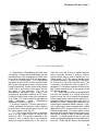


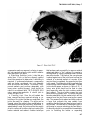


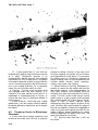
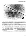


![1127117 - [PROJECT.TOC] - Performance Heating & Plumbing](http://vs1.manualzilla.com/store/data/005895106_1-55e9d6c83dbc31a8ba61d6bb401245cf-150x150.png)