1
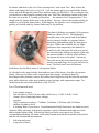
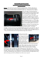
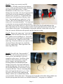
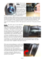
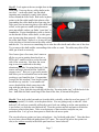
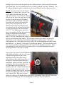
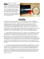
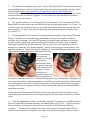
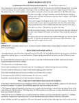
Kiron 28-105 f3.2-4.5
Cleaning Oily Diaphragm Blades
and Lens Re-lubrication on Three Particular Lenses.
By Prentice Fish, November 2010
version 1.1
Disclaimers: Here I am merely describing what I did on three manual focus Kiron 28-105
lenses, two in Canon FD mount and one in Minolta MD mount, and also one “parts lens” in
Nikon mount. I do this as a personal hobby and I lack lens repair skills/experience. What
follows reflects that perspective – this is not written for, or by, an experienced lens
technician. Don’t hold me responsible if you try this procedure and something goes very
wrong. That may happen. Don’t call me and I don’t want any lens repair work. You assume
all risks for whatever you do, and carefully consider consulting others who are qualified and
experienced. Also keep in mind that Kino Precision (Kiron was their brand name) probably
made changes over time when producing this lens, so my lenses may be different from yours.
My lenses were four (one being a “parts lens”) serial number *68***** models; said to be
the later models. Even the *68***** models varied over time as Kino made lens production
changes. The earlier serial number *63***** models are said to be different and more
difficult to repair.
Kiron produced a 56 page “Parts/Service Manual, Publication Number PL630” for this lens.
This Manual has parts diagrams, parts lists, disassembly procedures, and re-assembly
procedures. Very helpful. Study it. As of November 2010, you can download this complete
Kiron manual, from the helpful Kiron Klub, and Boggy, at this website:
http://www.boggys.co.uk/page21.html
If you get into trouble, or don’t want to bother with trying to fix the lens yourself, consider
sending the lens to an experienced lens repair person such as Ralph Innes, a member of the
Kiron Klub, whose website address is:
http://members.shaw.ca/f35mru20458/index.html
I don’t know Mr. Innes, have not met him nor communicated with him, and of course have
no financial connection to him. But several Kiron Klub members have mentioned his skills,
and I’d talk to and consider him if I were looking for someone to work on a lens of mine. As
always, evaluate your options and pick what you think is the best option for you at the time.
The Problem – Is the lens aperture stuck wide open? Oily lens diaphragm blades are not
unusual for old lenses, since the grease used on these lenses breaks down over the years, and
gets on the aperture blades, resulting in an aperture stuck wide open. Such was the case with
my four Kiron 28-105 f3.2-4.5 lenses that I obtained in 2010. Here is one way to test (there are
other test methods you may prefer) whether or not your lens has this problem: With the lens in
a camera, open the camera back, put the shutter on B shutter setting, and set the f-stop wide
open. Cock the shutter, look through the open camera back and the lens, press and hold down
Page 1
the shutter, and observe the size of lens opening in the “wide open” lens. Now release the
shutter, and change the f-stop to (say) f16. Cock the shutter again, press and hold the shutter
down, and look through the camera back and lens again, just like before. If everything is okay,
you should see a much smaller opening in the lens. But if the diaphragm remains wide open –
the same size as at the f3.5 setting you tried first – the aperture is not “stopping down” as it
should, and oily shutter blades may be the problem. You may also see the opening slowly get
smaller as you hold the shutter down. If this happens, the aperture is not “stopping down”
quickly as it should, and oily shutter blades may be the problem.
The photo left shows an example of oily aperture
blades on a Kiron 28-105. The diaphragm
assembly (that is the part in hand in this photo)
can be removed and the oily aperture blades
cleaned by disassembling only the front part of
the lens. While that would fix the oily blade
problem at least temporarily, this limited fix
would leave the old grease/oil in the rear part of
the lens and ready, perhaps, to migrate again onto
the aperture blades, or onto the glass surfaces,
leaving an oily haze on the glass. And on my
lenses the zoom/focus movement was very poor –
mostly loose and sloppy, but overly stiff in a few
areas. The likely cause was old lubricant
breakdown, also the likely cause of oily aperture blades.
So I decided to take apart both the front and rear parts of the lenses, clean the oily aperture
blades, clean any oily films on the exposed glass lens groups, and inspect them for
haze/fungus/other problems, remove the broken-down old grease from the helicoids and other
parts, and re-lubricate with a good synthetic grease having a wide temperature range. I'm
satisfied with the end result on all three of my 28-105's.
List of Tools/materials used:
*
Lens spanner wrench
*
flat screwdriver 1.0x40 (for the really small screws), 1.5x40, 2.0x40, 2.5x40
*
clamps (hose clamps and plastic clamps)
*
tweezers
*
JIS/Crosspoint screwdriver 1.7x40mm, 2.0x50mm, 2.5x50mm, and 3.0x50mm
*
phillips screwdriver 0x50
*
a cleaning fluid of your choice. I used denatured alcohol (from most any hardware store).
Opinions differ, and some, with greater experience, prefer Coleman brand camp stove fuel
and/or naptha (lighter fluid). You pick the fluid you decide you want to use; I'm not
recommending anything. Be aware of all safety hazards and read all the product safety labels
and take all recommended precautions.
*
dish soap and water
*
q-tips (lots of these)
Page 2
*
can of compressed air – readily available product
*
good synthetic grease with a wide temperature range
*
an Ottlite “Jupiter Magnifier Lamp”, or similar lamp with a magnifier built in, which
relieves eyestrain. This is not an absolutely essential item, but it sure helps.
*
a fluid of your choice for penetrating and loosening stuck threads on camera parts.
*
“ring wrenches” – different sizes of round rubber-like furniture leg cups (from most any
hardware store) or cane cups (from medical supply store).
The Kiron 28-105 Parts/Service Manual. Get this Manual (website listed on page 1) on the
Internet and study it. The Manual is a great resource with parts diagrams, parts lists,
disassembly procedures, and reassembly procedures. The parts names that now follow here are
usually consistent with the parts names in the Kiron 28-105 Parts/Service Manual.
Take Lots of Photos and Notes during Disassembly. Take lots of photos and notes during
disassembly. Go overboard here – you cannot have too many photos at different angles. Look
carefully (before taking lots of pictures) for things such as slots or notches and anything
different, so you can get the parts reassembled in the original position. Close-up photos from
many different angles are a real help later.
JIS/Crosspoint head screws, phillips head screws, threadlocker, appropriate solvents for
stuck threads, appropriate glass lens cleaning solvents, proper screw removal techniques,
etc. If these subjects are unfamiliar, consider even more carefully sending the lens to an
experienced lens repair person. Knowledge of these subjects is both helpful and beyond the
scope of what is presented here. Search the Internet for helpful information on these subjects.
You'll probably have to sift through the material to sort it out and find the “good stuff”. If not
familiar with lens disassembly, consider also finding a free or really cheap “beater lens” to
practice taking apart and reassembling before disassembling your Kiron 28-105.
Threadlocker: There are several kinds. MEK or acetone will at least soften most of them but
are slow to penetrate deep threads. If all is metal, a red hot soldering tip on the screw head for
30 seconds often softens the threadlocker enough for a steady torque to move the screw. When
cool, it becomes stiff as ever.
Set screws: Set screws have a sharp point and often are slot headed. The screwdriver should
fit exactly to reduce the chances of breaking off one side. Remove as much paint as you can so
the screwdriver blade can fit. When reassembling, it does not take much force to replace them
adequately. Consider using threadlocker or something else to keep them there. If several are
spaced around a ring tighten them evenly or else the ring could warp and bind.
//
//
//
//
//
//
//
//
Page 3
Disassembling the Kiron 28-105
(see Parts/Service Manual, §1.0 and following,
starting on page 43)
Step #1. Zoom the lens out to the 105mm focal length position. The Kiron Parts/Service
Manual refers to the part with the lens focal length scale on it as the “focal length indicator
ring”. It's the part with the numbers and infinity symbol on it. Find the three very small setscrews (slot heads, often with some black
paint, glue or silicone on the slot head) evenly
spaced around the focal length indicator ring;
one is very near the lens serial number.
Curved red arrow in photo left points to one.
Loosen those 3 small set-screws. Try not to
completely unscrew the 3 small set-screws so
that they drop out of the focal length indicator
ring. Putting them back in is a “PITA” (pain
in the arse). If one of the set-screws does fall
out, use a piece of thin closed-cell foam with
a hole in it to hold the small set-screw for reinstallation. Once the 3 set-screws have been
loosened, put your hand around the focal
length indicator ring, and unscrew that ring from the part Kiron calls the “rear mount
assembly”. Be sure to unscrew the focal length indicator ring in the correct direction. One way
to do that is to put the lens in the camera body. While holding the camera facing you with one
hand – which means the lens front will be closest to you and the camera body furthest from you
- with your other hand turn the focal length indicator ring counter-clockwise.
If it does not turn easily,
loosen the set-screws a bit
more, trying not to let them
fall out. If it does not turn
after all the set-screws have
fallen out, you've got a
problem. On my four
Kiron 28-105's, the focal
length indicator ring turned
fairly easily, with the set-screws loosened and still in
the ring. Photo right (above) shows the focal length
indicator ring unscrewed off of the rear mount
assembly. The rear mount assembly is the shiny
aluminum part, and everything to the right of that shiny part, in the photos above. The red
arrow points to one of the four “flathead screws” in the shiny aluminum part of the rear mount
assembly. Photo left (above) is an enlarged version of the same photo, showing the fine threads
(on the shiny aluminum part) from which you've just unscrewed the focal length indicator ring,
and also showing one of the four flathead screws that are now exposed.
Page 4
Step #2. Using your correctly sized JIS
screwdriver, carefully remove the four flathead
screws evenly spaced around the shiny aluminum
part shown in the photos above. Expect
threadlocker on these four screws. Try not to
damage the screw head. One one of my lenses the
screw head was already damaged, and I had to
drill the screw to remove it. I replaced the then
useless screw with a good one from my “parts
lens”. You may not have a “parts lens”, so be
careful. Once all four flathead screws are out,
remove the “rear mount assembly”. You may need
to rotate the rear mount assembly back and forth
just a little as you evenly remove it. Once it is off, slide off the focal length indicator ring.
Photo right shows the rear mount assembly and the focal length indicator ring off the lens; red
arrows point to those parts. Avoid bending or altering the aperture control arms in any way.
They are a precise link between the aperture and the aperture set ring.
Step #3. Remove the “name ring” - that's the lens
front cover that has the Kiron lens name on it, and
has 3 small set-screws holding it on. Loosen the
3 small set-screws on the name ring enough to get
it off, and leave the 3 small set-screws in the
name ring. If one does fall out, use a piece of thin
closed-cell foam with a hole in it to hold the
screw for replacement. Photo right shows the
name ring off the lens.
Step #2. Next off is the “lens assembly, 1st
group”. It is the front lens and unscrews. It
comes off as a unit and there is no need
normally to take it apart. On all four of my
models it refused to unscrew (even with
proper clamps), until applying a little
loosening fluid to the threaded joint and
letting it soak in for a few hours and loosen
up the threaded joint. Don’t be in a rush; let
the loosening fluid do its work before you try
to unscrew the lens. Choose a loosening fluid
that won’t harm the lens parts or you. Once
the lens is off, look for any round spacing
shim(s), and be sure to reinstall these when
you reassemble. Photo shows the 1st lens group out, laying flat on the table, along with the two
circular spacing shims that need to be reinstalled when the 1st lens group is re-installed.
Page 5
Step #3. Next to come
off is the “lens assembly,
2nd group”. It's the lens
below the one you just
took off in Step #2. This
lens also comes off as a
unit; as with the 1st lens
group, there is no need
normally to take the 2nd
lens group apart. For this
lens you should use a
lens spanner wrench. [Spanner wrenches are for
holding, not turning. Hold the spanner wrench and turn the lens under it.] The threads on this
lens may also need a little (not too much!) loosening fluid and a few hours before unscrewing
with the lens spanner wrench. On my four lenses, no loosening fluid was needed here. Once
this 2nd lens group is out, the diaphragm assembly is exposed, and you can see the forward
facing side of the diaphragm assembly. Photo right (above) shows the 2nd lens group out and in
hand.
Step #4. Take off the “grip”. It is the rubber-like
cover on the “zoom ring”. A bamboo skewer
works well to get under the grip edge and start
rolling it off. The grip slides or rolls off with
your fingers. There may be a little glue under
the grip, which you’ll first need to separate from
the zoom ring before taking the grip off. Again
use the bamboo skewer, or something wood
slipped under the grip, rather than a metal flat
screwdriver, although that works also. Once the
grip is off, you can see the black lens zoom ring
and the two slots (one on each side, 180° apart)
in which there is a “roller shaft” and “rollers” that are flat sided (meaning not completely
round). Photo shows the grip partly rolled off, the zoom ring with slot, and the very small
white colored “roller” around the “roller shaft” in the slot.
Before unscrewing anything more, turn the zoom
ring and note the stops for infinity and close focus.
The zoom ring should be reinstalled later in the
same position as you found it, so scribe a
continuous line on the shiny aluminum part
(“focusing limit ring”) and on the black zoom ring.
The red arrow in this photo points to a continuous
scribe line on both parts. When the lens is
reassembled, this line should be in the same
position as you scribed it.
Page 6
Step #5. Look again at the two straight slots in the
zoom ring. Unscrew the two roller shafts in the
two slots – each roller shaft has flat sided
(meaning not completely round) white plastic
rollers around the roller shaft. Red arrow in photo
points to the flat sided small white plastic roller
surrounding the roller shaft in the zoom ring slot.
Take great care in removing these roller shafts and
rollers, as the parts are small and replacement
parts unavailable, unless you find a “parts lens” to
cannibalize. Expect threadlocker (such as loctite)
on the threads of these roller shafts, so take great
care in removing them properly. After unscrewing
the roller shaft about 5 turns or so, it may still stay
in the slot due to friction between the white rollers
and the slot. Use tweezers or something else to take the roller shafts and rollers out of the slots.
Try to remove the shaft and the surrounding white roller as a unit. The roller may slide off the
shaft; put it back on correctly.
Now loosen (just a few turns, don’t unscrew
all the way out as putting them back in is a
PITA) the 3 small set-screws on the forward
side of the zoom ring. Note how the zoom
ring is now not connected to the shiny
aluminum part (the “focusing limit ring”) that
rotates and stops when it hits the “helicoid
stopper screw”. But you’ve got scribe marks
that allow you to reassemble later in the same
position as you found the lens. Congratulate
yourself for this wisdom! Now loosen (again,
not all the way out) the 3 even smaller setscrews that hold the black zoom ring to the
ring with the red dot on it (the “focusing
index ring”). Now slide the ring with the red dot (the “focusing index ring”) off the back of the
lens. And slide the black zoom ring off the front of the lens, as shown in the photo.
Step #6. Now pick up the lens and rest it on the table vertically, so that the rear lens group (“4th
lens group mount”) is visible, as in the photo below. You are getting ready to take the “outer
helicoid” off, and you eventually will need to put it back on, ending up in the same position as
it was before you took the outer helicoid off. Note the various notches and parts to which the
red arrows point in this photo. Take several pictures of these notches and parts on your
particular lens. Let's go over these parts to which the red arrows point.
The curved red arrow points to a brass colored part – the “helicoid guide plate”. Note that there
are two brass colored helicoid guide plates 180° apart. The curved red arrow also points to a
slot (a slot without a notch) in the black part known as “inner helicoid”.
Page 7
The red triangle points to a notch in the shiny
aluminum part called the “guide ring”.
The straight red arrow points to a slot (but a
slot with a notch) in the “inner helicoid”.
[On my Nikon mount Kiron only, there was
no notch in either of the slots of the inner
helicoid, so I scribed a line on the rim of the
inner helicoid opposite the guide ring notch.]
Check that the guide ring is pushed all the
way down on your work table, so the the lens
is in the 28 mm position. Next to the guide
ring (and attached to it) is a black part – the
outer helicoid. Note the part touching your
work table – it is the “1st group drive ring”, and the part from which you unscrewed the large
lens called the “1st lens group”. Holding the 1st group drive ring from turning on your table,
note that the guide ring will not turn, but that the outer helicoid turns easily, and moves both the
outer helicoid and the guide ring vertically up and down. Turn the outer helicoid only a little to
see this – say, ¼ turn – so that you don't take the outer helicoid off just yet. Check again that
the guide ring is all the way down, in the 28 mm position. Put a mark anywhere on the low
part on the black outer helicoid - some sort of white painted spot or short white vertical line
works well since it can easily be seen against the black outer helicoid. [You can also scribe a
mark on the outer helicoid if you prefer.]
Again holding the 1st group drive ring from turning on your worktable, turn the black outer
helicoid slowly so that it rises vertically and comes off. The moment it comes off, note the
position of your white mark on the outer helicoid, and put another mark directly below that
mark on the 1st group drive ring. The purpose of these two white marks, one vertically above
the other: during re-installation of the outer helicoid, you'll put one mark vertically above the
other as you attempt to re-engage the outer helical in the same place where you removed it.
[When the outer helicoid is eventually re-installed much later, check that the notches (in the
photos you took) line up as you found them, before taking the outer helicoid off.]
Step #7. The outer helicoid is now off, but still attached to the guide ring, as shown in photo
left. Unscrew the outer helicoid from the guide ring, but first scribe a line on both, and count
the turns (roughly 8-11turns)
needed for separation, so
you can get these two parts
together exactly as you
found them. Then unscrew
the guide plates from the
guide ring. Photo right
shows one guide plate and
screws off; one still on and
about to be removed. Note
that the sets of screws
Page 8
holding the guide plates onto the guide ring have different heads, which match different holes
in the guide ring. One set of guide plate screws is called “panhead”; the other “flathead”. The
“F” mark on the photo right is a reminder to put the two flathead screws in those two holes.
Step #8. Now you can see the 4 L shaped
(more or less L shaped, these slots are a bit
wavy) guide slots in the part (the “cam
ring”) just exposed. Two of these L shaped
slots are on one side of the cam ring, two on
the other. Each slot has two JIS headed
roller shafts with a completely round (not
flat sided) white plastic roller around the
screw. [Note: on my Kiron 28-105 in
Minolta mount, these roller shafts heads
were slotted, not JIS, and also had washers,
even though bearing a lens serial number
*68*****. The Manual states otherwise;
here is an example of a Kino lens production
change not mentioned in the Manual.
Possibly my Minolta mount model was an
early 28-105 lens, when Kino was using up
leftover parts from an earlier model.] The two most forward roller shafts (one in each L
shaped slot on each side of the lens) hold the diaphragm assembly in place. But before
removing these two roller shafts and rollers, scribe a line on the diaphragm assembly and the
inner helicoid – see section 1.14 on page 45 of the Repair Manual. The reason for this scribe:
there are two possible mounting positions (180° apart) for the diaphragm assembly. When
reassembling the scribe line will tell you which of the two possible diaphragm assembly
mounting positions is the same as found.
Unscrew those two most forward JIS headed
roller shafts and rollers - they are 180° apart.
A thread locking fluid may have been
applied previously. Take great care in
removing these roller shafts and rollers, as
the parts are small and replacement parts
unavailable, unless you find a “parts lens” to
cannibalize. Once unscrewed a few turns,
the roller shaft is out of its hole, but
probably still in the L shaped slot because of
friction with the white plastic roller. Use
tweezers or another way to get the two most
forward roller shafts and rollers out of the
two L shaped slots. Red arrow in photo
shows one of the rear JIS headed roller shafts and its surrounding white roller still in the lens;
the front one (holding one side of the diaphragm assembly) is unscrewed and out.
Page 9
Step #9. Now the diaphragm assembly
slides/falls (gently, please) out the front of the
lens. Once out in your hand, examine the
diaphragm assembly, and try gently moving the
levers that move the aperture blades. When the
blades move from the “stuck wide open”
position, you should be able to see clearly the
sticky oil on the aperture blades, if oily blades
are the problem, but sometimes only the pivots
are stiff with dry oil. On my two Canon mount
Kiron 28-105 lenses oily blades were the
problem. The photo shows the diaphragm
assembly in hand, and oily aperture blades now
“stopped down” gently from the “stuck wide open” position.
Try removing the sticky oil on the aperture
blades without disassembling the diaphragm
assembly. But before putting the diaphragm
assembly in alcohol (or other cleaning fluid of
your choice) remove, with a lens spanner
wrench, the ring (the “retainer”) on the lens
assembly (“3rd lens group”) on the diaphragm.
Then mark (for instance, with a magic marker
dot on the lens outer part) the upper side of the
just exposed glass, so you can get it back in
with the proper glass side up. Or you can mark
the upper side with some tape – fold the tape
over to grasp when you eventually reinstall the glass and remove the tape.
Remove the upper piece of glass and set it aside carefully. Photo above shows upper glass
piece and black retainer out of the diaphragm assembly. Now there is only the lower piece of
glass in the diaphragm assembly. That would not move; perhaps it is glued in place. No
matter, since I'll be cleaning all exposed glass surfaces on each lens group, in case the
grease/oil that migrated to the diaphragm blades has also formed an oily film on the exposed
glass surfaces. [If you don’t remove the top glass piece, and wash the diaphragm assembly in
your chosen cleaning fluid, the fluid will get between the two pieces of glass, and stay there, a
bad situation, mildly put.]
A general thought before returning to the oily diaphragm problem. While you have a chance to
examine each lens group individually, do so carefully, as the lens groups are taken out. Besides
examining the outer glass surfaces of each lens group for problems, look for fungus or oily
haze on the interior (that is, the non-exposed) glass surfaces of each lens group. Hopefully
there is no problem on the non-exposed glass surfaces; if there is, consider dealing with it.
What is the point of a mechanically good lens with hazy or oily glass? The goal here is clean
and bright glass when everything is re-assembled, for those great pictures you'll be taking.
Now back to the oily diaphragm. Put the diaphragm assembly in the cleaning fluid of your
Page 10
choice. Gently work the aperture blades open and closed, with the lever (called the “blade
operating ring”) that has a spring attached to it, so the cleaning fluid can get at the sticky oil on
the blades. If the blades don't move, maybe the cam on the other lever (called the “aperture
cam ring”) is holding the blades open. So move the aperture cam ring in one direction. Try
moving the blade operating ring again with gentle pressure, and see if the blades now move. If
not, move the aperture cam ring in the opposite direction, and once again try moving the blade
operating ring with gentle pressure, and see if the blades now move. If nothing moves, let the
diaphragm assembly soak overnight in the cleaning fluid, and try again.
Often this will remove the oil and free up the aperture blades so they are “snappy” once again,
and “snap down” when you let go of the blade operating ring. Move the other lever as well, to
see if the blades now open and close properly. Count your blessings if this happens! It worked
on one of my Canon 28-105 lenses, but not the other. On the other one I took the blades out of
the diaphragm assembly, which is a PITA. With the benefit today of hindsight, on the aperture
assembly that did not clean up, as an assembly, with denatured alcohol, I'd consider using (and
observing all safety precautions) other “more powerful” cleaning fluids commonly used on
camera parts. But that's just an opinion – you decide. As a general rule, avoid using acetone or
MEK because some lens aperture blades are plastic and will be warped by such solvents.
Suppose the blades cannot be cleaned the easy way –
by cleaning the entire assembly as a unit. In other
words, suppose the blades need to be taken out of the
diaphragm assembly. Review §1.19 – §1.21 of the
Manual. To get the blades out of the diaphragm
assembly, remove the three small screws in the
forward-facing part of the diaphragm assembly - the
part you see in this photo. Follow the steps in the
Manual. Before taking out the three small screws,
scribe a line on the “diaphragm blade retainer plate”
and onto the “diaphragm housing”, for easier
reinstallation in the same position as found. Red
arrow in photo right points to two such scribe lines.
Clean the blades and the other parts shown in the
photo right. The photo on the next page shows the
blade reassembly overlap pattern (for my lens –
check the manual to see if your lens overlap pattern
is different) on the “blade operating ring”. It's a
PITA, to be avoided if you can clean the blades
without taking them out of the diaphragm assembly.
You may need to try different ways to correctly reassemble. I found it easiest, for me, to put a round
cylinder about 3-4 inches tall, like a rubber name
ring removal tool (also known as a “ring wrench”),
on the work table, and put the “blade operating ring”
on the round cylinder, lever facing down, and then
Page 11
put the blades correctly on the blade operating ring (final blade goes under the initial blade, as
shown in photo below), and then put the “diaphragm blade retainer plate” on, getting the little
stub posts on the blades into corresponding holes in the diaphragm blade retainer plate. These
parts are shown disassembled in photo above. Next, I carefully moved, with tweezers, the
assembled parts to the diaphragm assembly and got it into place, so the three screws that hold
everything together could be installed. Not easy; took several tries; things happened. Blades
move out of position quite easily. You may find a better way.
Once the three screws are in, reattach the “blade
operating spring” to the “blade operating ring”.
Clean both sides of both pieces of glass. To
clean the glass side facing the blades, use the
blade operating ring to open the blades to the
“wide open” position. Reinstall the piece of
glass you took out, original side up.
By moving the blade operating ring, check
whether the blade operating ring fully opens the
diaphragm, and stops just after fully opening the
diaphragm. If an adjustment is needed, adjust
the “diaphragm stopper plate” so that the blade
operating ring stops just after fully opening the
diaphragm.
Step #10. Remove carefully the remaining two roller shafts and rollers in the L shaped slots in
the cam ring. The rear lens group (“4th lens group mount”) now slides (gently, please) out.
Photo shows 4th lens group mount out (right side of photo) and diaphragm assembly out (left
side of photo) and four small roller shafts
and rollers. For display purposes only, one
roller shaft and roller is shown in the
diaphragm assembly and another shown in
the 4th lens group mount; two are on the
table. This picture is from the disassembly
of my Minolta mount Kiron, which
happened to have slot screw (not JIS)
headed roller guides and washers.
According to the Parts/Repair Manual, there
is no roller guide washer on the *68*****
models. That was the case with my other
three lenses, which also had JIS headed
roller guides instead of slot headed roller
guides, but not my Minolta mount model.
Page 12
Step #11. Remove carefully the remaining
two roller shafts (180° apart) and rollers in
the (more or less) straight slot in the cam
ring. These two roller shafts screw into the
“inner helicoid”. Red arrow points to one
such roller shaft and roller from my Minolta
mount Kiron. These two roller shafts were
slot headed; most will be JIS headed. These
two roller guides and rollers are smaller
than the two roller guides and rollers
previously removed from the L shaped slots
in the cam ring.
Step # 12. With a
spanner wrench, remove
the cam ring retainer, as
shown in left photo.
Then slide off the cam
ring. Right photo shows
cam ring retainer (on
photo far right), and cam
ring (in center of right
photo) off.
Step #13. With a
spanner wrench,
remove the zoom
stopper ring from
the inner helicoid,
shown in photo
left. Photo right
shows the zoom
stopper ring (left
side of right photo)
and inner helicoid
(right side of right
photo) out. A
comment: if this step is too difficult, consider not doing it. Even though these parts may have
much old grease, which should be removed, you may well be able to remove the grease and
clean these parts as an assembly in a container of your chosen cleaning fluid. On my lenses
this step was not hard, so I did it. A further comment: along this line of thinking, perhaps you
can consider skipping the previous two steps, and adequately clean the assembly. But keep relubrication in mind. I chose to perform all steps because it wasn't hard and it made relubrication easier; you might choose otherwise and that may (or may not, I don't know) work
adequately enough.
Page 13
Step #14. Remove the “helicoid
stopper”, which is the small screw against
which the “focusing limit ring” hits when
the focus is moved from close focus to
infinity. Then remove the focusing limit
ring. The picture shows these parts
removed, with the red arrow pointing to
the small so-called “helicoid stopper”.
The focusing limit ring is the shiny
aluminum part on right side of photo. On
the photo left side, the large black part is
the “1st group drive ring”.
Re-Assembly.
At this point, the old grease and oil have been cleaned off the parts. The oily diaphragm
assembly has been cleaned and (if taken apart, re-assembled) is ready for re-installation. The
individual lens groups have been examined and found to be clear, bright, and without
significant problems, with any oily films on the exposed glass surfaces removed. No
irreplaceable parts were ruined during disassembly. So the lens will be re-assembled, and
you've got great modern synthetic wide temperature range grease on hand, which you've
decided will give your lens just the right feel (for you) when zooming and focusing. In general,
reassembly is the reverse of disassembling. The Kiron Parts/Service Manual covers reassembly in §2.0 and following, starting on page 47. Here are some additional thoughts.
1. When putting the focusing limit ring on the 1st group drive ring, the Manual (§2.12) has a
diagram (Figure 2), and states the focus limit ring should be screwed onto the 1st group drive
ring until the rear rim of the focus limit ring is flush with the “start of the thread on the 1st
group drive ring”. I found the “start of the thread” hard to determine very accurately on my
lenses. Doing the best I could to find the “start of the thread”, I also put the cam ring on
(temporarily) as far as goes, and made sure there was a small gap between the cam ring and the
focus limit ring, in both the infinity and close focus positions. If there is no small gap in both
positions, the cam ring could bind against the focus limit ring. Once a small gap existed in
both positions, the “helicoid stopper” was screwed in. Took the cam ring off again at this point
of course.
2. The zoom stopper ring has threads and is pretty flexible. It would be fairly easy to get it
cross-threaded if one attempts to get it back onto the inner helicoid in the same way as it was
removed – that is, with a spanner wrench. So I chose to put the zoom stopper ring into the 1st
group drive ring, to the point where it rested evenly against the stop shoulder inside the 1st
group drive ring. Holding that zoom stopper ring in place against the stop shoulder with my
fingers, I put the (already newly greased) inner helicoid inside the (already newly greased) 1st
group drive ring, and carefully screwed the inner helicoid into the held zoom stopper ring.
Worked well for me.
Page 14
3. The Manual recommends using “glue” such as Three Bond 1401C on lots of threads when
re-assembling the lens, such as on the threads of the cam retainer ring and the cam ring. Three
Bond's website: http://www.threebond.co.jp/en/product/series/locking/1400list.html
describes this product, and it appears to be a rubbery threadlocker allowing “fairly easy” future
removal of the parts to which it is applied. Of course there are other threadlocker products
available that you may choose.
4. Pay special attention to §2.19 through §2.23 of the Manual. §2.19 states that the Guide
Ring should be screwed on to the outer helicoid all the way, and then retracted 1 to 2 turns. On
my three lenses, it took about 10 turns to screw the Guide Rings all the way on, and they were
then retracted 1-1/2 turns. Note also the important 9mm spacing described in Figure 4 and
§2.22 and §2.23.
5. This paragraph discusses some issues arising during reassembly of my Canon FD mount
Kirons. Consider your own mount type, and whether you may have similar or different
problems for your mount. On Canon FD mounts, the aperture cam ring must first be in the
position in photo right below, and not in the position in photo left below, when you put the
diaphragm assembly into the inner helicoid. Otherwise it won’t work right later, when you
attempt to re-attach the “rear mount assembly”, and try to insert the post on the aperture cam
ring between the two forks on the aperture signal lever. Note the difference between the cam
ring positions in photo right below and photo left below.
When you reinstall
the rear mount
assembly, be careful
that you don't
inadvertently move
the aperture cam ring
to the position in the
left photo. At that
point in the reassembly process, the
incorrect position of
the aperture cam ring is hard to see, without looking inside very carefully with a flashlight. On
one of my Canon lenses, when attempting to re-install the rear mount assembly, I inadvertently
moved the aperture cam ring to the photo left position, which meant I had to take some parts
out again, and move the aperture cam ring to the position in the right photo, and reassemble
again from that point.
On my particular Nikon mount Kiron, the aperture cam ring and its cam are made in such a
way that the problem noted above (cam ring getting into position shown in left photo) cannot
occur.
6. After the diaphragm assembly is re-installed, and the 4th lens group is re-installed, and it's
time to re-install the rear mount assembly, the Manual states, in §2.26, to “...Replace the Rear
Mount Assembly, matching the coupling levers with those in the Diaphragm Housing
Assembly...”. To match the coupling levers more easily on my Canon mount Kiron lenses, I
found it best to first move the aperture cam ring lever (which stays in place where you put it)
Page 15
towards the other lever on the diaphragm assembly – the “blade operating ring” lever (which is
moved to a limit position by a spring, and stays there until something pushes it). Then I pushed
the diaphragm actuator lever away from its spring, and held the forked lever (aperture control
lever) over the post on the aperture cam ring lever (the post is going to end up between the
forks), and put the rear mount assembly on, and then released the actuator lever. Try whatever
works best for you, and your mount type.
Once the rear mount assembly is re-installed, use the f-stop ring to make sure the aperture
assembly is working correctly. When checking this on Canon FD mount versions, keep in
mind that, when the breech lock ring of the Canon FD lens is turned to the "off camera"
position, the aperture controls on the back of the lens do not function the same as when the ring
it turned to the "on camera" position. So on Canon FD lenses make sure the breech lock ring is
in the “on camera” position before checking the aperture assembly.
The aperture blades should stop down at f 16 and remain wide open at f 3.2. If the blades don’t
fully open at the widest aperture setting - f 3.2 – you can adjust the blades a little from the lens
front. To do this, loosen slightly the 3 screws in the front part of the aperture, shown in the
photo. Note the slots next to these 3 screws. Using a pointed
tool in one of those slots, rotate the assembly a little – the 3
screws are in small slots, so the assembly can rotate just a
little. When the aperture blades are where they should be at
the widest aperture setting, retighten the 3 small screws. Let
me note a potential problem here – the Manual does not
discuss this adjustment, so maybe some future problem(s) will
occur if this particular adjustment is done. The Manual does
cover an adjustment to the diaphragm stopper plate – made on
the other side of the aperture assembly – see §2.11. Of course
that adjustment should be made when one has access to that stopper plate, but here the only
access (without some disassembly and re-assembly) is on this front side. Any thoughts re
risks/benefits by knowledgeable persons? Maybe this is an “undocumented feature”; maybe it
should be avoided.
Finally, I'd like to gratefully acknowledge the excellent help and comments of Mel Smith, who
kindly reviewed earlier drafts. That said, any mistakes here are the responsibility of the author
alone. Should you detect something(s) that needs correction, please send your constructive
comments to: *prenticefish*@*msn.com*. All such comments welcomed and appreciated. [The
e-mail address is not correct in the hope that spammers can't grab it and use it to peddle stuff.
Please cut and paste the address into your e-mail, then remove the *.]
Copyright © 2010 Prentice Fish
All Rights Reserved
Page 16