1
Instrumentation Scientifique de Laboratoire
FP93 5G2
User and Maintenance manual
Pensky-Martens automated flash point Analyzer
ASTM D93(A&B), IP 34(A&B), NF EN22719 & ISO 2719 METHODES
Instrumentation Scientifique de Laboratoire - BP 70285 - 14653 CARPIQUET CEDEX FRANCE
Tel: (+33) 2.31.26.43.00
Fax: (+33) 2.31.26.62.93
Page intentionally blank.
Page 2
FP93 5G2 User and Maintenance Manual
DOCV206A001-f
FP93 5G2
Version
Concerned Part
Date
FP93 5G2 Analyzer use Part
A
Original issue
97/11
FP93 5G2 Analyzer advanced use Part
A
Original issue
97/11
FP93 5G2 Maintenance Part
A
Original issue
96/11
B
Flash point detection replacement
96/12
C
Revision of the manual
98/01
D
Revision of the manual
00/05
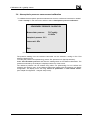
Version
§ concerned
Part 2 § 6.5
e
f
Part 4 § 1.4
Part 4 § 4
Part II § 4.2.1
Part IV § 1.4.2.14
Part IV § 4
DOCV206A001-f
Modifications
Date
Configuration menu: modification of the “Safety parameters”
menu
Alarm messages update
Spare parts list creation
08/07/02
FEV 01143: rounded modification
Alarm update: “Abnormal atmospheric pressure”
01/10/02
Spare parts list update
FP93 5G2 User and Maintenance Manual
Page 3
ISL FP93 5G2 Software © 2000, ISL
This software is owned by ISL and is registered under the registration number IDDN.FR.001.110041.00.R.P.2000.000.30000 at
the « Agence pour la Protection des Programmes », 119 Avenue de Flandre - 75019 PARIS. It is protected in France by the
« Code de Propriété Intellectuelle » laws and internationally by international treaty provisions, and all other applicable national
laws. It must not be copied, reproduced, adapted, translated, rented or disassembled. This also applies to the accompanying
manuals.
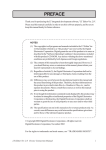
INFORMATION
Information in this document is subject to change without notice and does not represent a commitment on the part of ISL. ISL
provides this document "as is", without warranty of any kind, either expressed or implied, including, but not limited to, the
particular purpose. ISL may make improvements and/or changes in this manual or in the product(s) and/or the program(s)
described in this manual at any time. This product could include technical inaccuracies or typographical errors. Changes are
periodically made to the information herein; these changes may be incorporated in new editions of the publication. Reproduction
of any part of this manual without express written permission is forbidden...
Page 4
FP93 5G2 User and Maintenance Manual
DOCV206A001-f
FP93 5G2
Caution
This ISL Analyzer has been carefully designed, manufactured and
inspected for quality. It has been equipped with a number of safety
features.
However, the use of this Analyzer may involve the handling of solvents,
chemicals, and other potentially dangerous flammable, toxic, etc.)
materials. Please exercise caution when- handling these materials while
operating the Analyzer.
Please:
• read the manual
• wear proper protective clothing
• perform all suggested service procedures
• use care to prevent accidents.
The manufacturer accepts no responsibility for any damage or liability
arising from the use of Analyzers.
DOCV206A001-f
FP93 5G2 User and Maintenance Manual
Page 5
Contents
PART I USING THE FP93 5G2
I-11
1 - GENERAL
1.1 -ISL COMPANY PROFILE
1.2 -SYMBOLS AND TYPOGRAPHICAL CONVENTIONS
2 - GENERAL SCOPE
3 - PRESENTATION OF THE FP93 5G2
3.1 -THE ANALYZER
3.1.1 - Control unit
3.1.2 - Test unit
3.2 -PRESENTATION OF THE PENSKY - MARTENS ELEMENTS
3.2.1 - Heating block
3.2.2 - Cooling system
3.2.3 - Stirring system
3.2.4 - Ignition
3.2.5 - Flash point detector
3.2.6 - Sample temperature probe
3.2.7 - The test arm
3.3 -THE AVAILABLE ACCESSORIES
3.4 -SOFTWARE CONFIGURATION
4 - FP93 5G2 SYSTEM SAFETIES
4.1 -FAULTS AND ALARMS
4.1.1 - Fire detection
4.1.2 - Faults switching the Analyzer to standby
4.1.3 - Faults refusing a test start and stopping a test run
4.1.4 - Report alarms
4.1.5 - Warning alarms for non conformity correction
4.2 -PASSWORDS
5 - SPECIFICATIONS, INSTALLATION AND SWITCHING ON
5.1 -CHARACTERISTICS
5.2 -AFTER UNPACKING
5.3 -CONNECTIONS
5.3.1 - Gas supply (gas ignition)
5.3.2 - Connecting the igniter
5.3.3 - Flash detector and probe connection
5.3.4 - Connecting the printer
5.4 -HANDLING PRECAUTIONS FOR THE LCD SCREEN
5.5 -SWITCHING ON
5.5.1 - Switching on display
5.5.2 - Auto-test
6 - THE ANALYZER INTERFACE
6.1 -KEYPAD
6.2 -DISPLAY
6.3 -TEXT EDITING
I-13
I-13
I-14
I-15
I-16
I-17
I-17
I-18
I-19
I-19
I-19
I-19
I-20
I-21
I-22
I-22
I-22
I-22
I-23
I-23
I-23
I-23
I-23
I-23
I-24
I-24
I-25
I-25
I-26
I-27
I-28
I-28
I-28
I-28
I-28
I-29
I-29
I-30
I-31
I-31
I-32
I-33
Page 6
FP93 5G2 User and Maintenance Manual
DOCV206A001-f
FP93 5G2
6.4 -ENTERING A NUMERIC VALUE
6.5 -FLIP-FLOP ENTRIES
7 - MEASUREMENT CHECKS
7.1 -TEMPERATURE MEASUREMENT
7.1.1 - Temperature probe reading correction
7.1.2 - Response time correction
7.2 -ATMOSPHERIC PRESSURE MEASUREMENT
8 - THE FLASH POINT TEST
8.1 -PREPARATION AND PROCEDURE
8.1.1 - Sampling
8.1.2 - Preparation
8.2 -TEST PROCEDURE
8.2.1 - Selecting a test procedure
8.2.2 - Test starting
8.3 -TEST RUNNING
8.3.1 - Igniter check after pressing "RUN START":
8.3.2 - Manual test stop
8.4 -STANDARD TEST STOP
8.4.1 - Flash on first flame test
8.4.2 - Flash point detection before the standard phase
8.5 -CLEANING THE TEST SET
8.6 -TEST COVER AND ACCESSORIES CLEANING
9 - REGULAR MAINTENANCE
I-33
I-33
I-34
I-34
I-34
I-34
I-34
I-35
I-35
I-35
I-35
I-36
I-36
I-37
I-39
I-39
I-39
I-39
I-40
I-41
I-41
I-41
I-42
PART II ADVANCED USE OF THE FP93 5G2
II-43
1 - GENERALITIES
2 - THE MAIN MENU
3 - CALIBRATION: THE « QUALITY »MENU
3.1 -SAMPLE TEMPERATURE MEASUREMENT CALIBRATION
3.2 -PERIODICITY AND TEST START REFUSAL
3.3 -PROBE CORRECTION TABLE
3.4 -ATMOSPHERIC PRESSURE MEASUREMENT CALIBRATION
4 - RUN ENVIRONMENT DEFINITION: THE “RUNS ENVIRONMENT” MENU
4.1 -THE “ISL FP93 5G2” TEST PRINCIPLE
4.2 -TEST PARAMETERS
4.2.1 - Identification and definition parameters
4.2.2 - Fast phase
4.2.3 - Standard phase
4.2.4 - Final phase
4.3 -CUSTOMIZING A TEST : ENTERING PARAMETERS
4.4 -MODIFICATION OF AN ALREADY EXISTING TEST
4.5 -SAMPLES EDITION AND DISPLAY
4.6 -SPECIFICATION PAGES EDITING AND DISPLAY
4.7 -OPERATORS NAME EDITION AND DISPLAY
4.8 -CUSTOMIZING RUN MODE SCREEN
5 - DIAGNOSTICS AND MEASURES : THE “SERVICE” MENU
5.1 -DIAGNOSTICS AND MEASURES DISPLAYS
5.1.1 - Diagnostics display
5.1.2 - Measures display
II-45
II-46
II-47
II-48
II-51
II-51
II-53
II-54
II-54
II-54
II-55
II-56
II-57
II-58
II-59
II-61
II-61
II-62
II-63
II-63
II-64
II-64
II-64
II-65
DOCV206A001-f
FP93 5G2 User and Maintenance Manual
Page 7
5.2 -DIFFERENT DIAGNOSTICS
5.2.1 - Heating
5.2.2 - Cooling
5.2.3 - Printer
5.2.4 - RS-232 External link
5.2.5 - Stirrer
5.2.6 - Igniter
5.2.7 - Electrical igniter
5.3 -SERVICE PRINTING, INTERNAL PARAMETERS
5.3.1 - Service parameters list printing
5.3.2 - Measures printing
5.3.3 - Regulation check
5.3.4 - Printer reset
6 - CONFIGURATION: “ANALYZER SETUP” MENU
6.1 -PRINTER SETUP
6.2 -RS 232 LINK SETUP
6.2.1 - Hardware setup - communication parameters
6.2.2 - Software setup
6.2.3 - Data flow control
6.2.4 - Computer on-line
6.2.5 - Transmitted data
6.2.6 - Result message format
6.2.7 - External link test
6.3 -SERVICE: SERVICE PARAMETERS
6.3.1 - Regulation parameters
6.3.2 - Buzzer pulse width
6.3.3 - Modification of the sample temperature calibration values
6.3.4 - Upload / Download
6.4 -ISL ADJUSTMENT
6.5 -RUN DEFAULT VALUES
6.5.1 - Power on parameters
6.5.2 - Safety parameters
6.5.3 - Run parameters
6.6 -LABORATORY SETUP
6.7 -REAL TIME CLOCK
7 - ACCESS LEVELS AND PASSWORDS: THE “ACCESS” MENU
7.1 -SELECTION OF THE ACCESS LEVEL
7.2 -MODIFYING PASSWORDS
8 - FULL MODE RUN : THE “FULL MODE RUN” MENU
8.1 -USING CURRENT TEST PROGRAM
8.2 -WITH MODIFIED CURRENT TEST PROGRAM OR ANOTHER PROGRAM
8.3 -EXITING FULL MODE
9 - RESULT OF THE LAST TEST RUN: THE “LAST RUN RESULT”
9.1 -DISPLAYING THE LAST RUN RESULT
9.2 -EXTERNAL LINK TRANSMISSION VALIDATION
10 -PRINTINGS: THE “PRINTING” MENU
10.1 - PRINTER RESET
10.2 - ENVIRONMENT PRINTING
10.2.1 - One sample contents
10.2.2 - One spec page contents
10.2.3 - One test contents
10.3 - PRINTER LINK TEST
Page 8
FP93 5G2 User and Maintenance Manual
II-66
II-66
II-66
II-66
II-66
II-66
II-67
II-67
II-67
II-68
II-68
II-68
II-68
II-69
II-69
II-69
II-70
II-71
II-72
II-74
II-74
II-76
II-76
II-76
II-77
II-78
II-78
II-78
II-80
II-80
II-81
II-81
II-81
II-81
II-82
II-83
II-83
II-83
II-84
II-84
II-85
II-85
II-86
II-86
II-86
II-87
II-87
II-87
II-87
II-88
II-88
II-88
DOCV206A001-f
FP93 5G2
11 -RESULTS AND PRINTING: THE “RESULTS MEMORY” MENU
11.1 - RESULTS PAGES
11.2 - STATISTICS
11.3 - RESULTS DISPLAY / PRINTING AND TRANSMITTING
11.4 - RESULTS PAGES ALLOCATION
11.5 - PAGE CLEANUP
11.5.1 - One page contents cleanup
11.5.2 - Delete page name and contents
PART III
FP93 5G2 MAINTENANCE
II-89
II-89
II-90
II-91
II-91
II-91
II-92
II-92
III-93
1 - GENERAL
2 - EXTERNAL OPERATIONS
2.1 -REPLACING THE SAMPLE TEMPERATURE PROBE
2.2 -REPLACING THE FLASH POINT DETECTION
2.2.1 - Detection kits
2.2.2 - Assembling / dismantling the ionization electrode
2.2.3 - Assembling / dismantling the thermocouple detector
2.3 -ASSEMBLING / DISMANTLING THE STIRRER
2.4 -ASSEMBLING / DISMANTLING THE IGNITER
2.4.1 - The electrical igniter
2.4.2 - The gas igniter
2.5 -ADJUSTING THE FLASH POINT DETECTION THRESHOLD
3 - INTERNAL OPERATIONS
3.1 -ANALYZER DISMANTLING / ASSEMBLING FOR MAINTENANCE OPERATIONS
3.1.1 - Dismantling / assembling of the Analyzer housing cover
3.2 -BATTERY TROUBLES: REPLACING THE BATTERY
3.3 -FIRE DETECTION, THERMOFUSE REPLACING
3.4 -FUSES
3.5 -CONNECTING AN EXTERNAL ALARM DEVICE
3.5.1 - Characteristics of the external alarm connection
III-95
III-96
III-96
III-96
III-96
III-96
III-97
III-98
III-98
III-98
III-99
III-100
III-101
III-101
III-101
III-101
III-102
III-102
III-103
III-103
PART IV
IV-105
APPENDICES
1 - ALARMS
1.1 -CATEGORIES OF ALARMS
1.1.1 - Fault alarms
1.1.2 - Report alarms
1.1.3 - Warning alarm
1.2 -DISPLAYING ALARM CAUSE, STOPPING AUDIO ALARM
1.3 -ALARM TREATMENT
1.4 -FAULT ALARMS
1.4.1 - Switching to standby
1.4.2 - Summary of some faults
1.5 -REPORT ALARMS
1.5.1 - Report alarms summery
1.6 -WARNING ALARMS
2 - RS 232C STANDARD EXTERNAL LINK
2.1 -RS 232C LINK CHARACTERISTICS
2.1.1 - Hardware configuration
2.2 -EXAMPLE OF MESSAGES SENT
DOCV206A001-f
FP93 5G2 User and Maintenance Manual
IV-107
IV-107
IV-107
IV-107
IV-107
IV-108
IV-108
IV-108
IV-108
IV-109
IV-112
IV-112
IV-113
IV-114
IV-114
IV-114
IV-114
Page 9
2.3 -EXAMPLE OF THE USE OF RS-232C LINK WITH A PC
2.3.1 - Analyzer configuration
2.3.2 - Software configuration
3 - MASTER PASSWORDS
4 - SPARE PARTS LIST
FP93 5G2 230V - 50/60HZ GAS
FP93 5G2 115V - 50/60HZ GAS
FP93 5G2 230V - 50/60HZ ELECTRIC
FP93 5G2 115V - 50/60HZ ELECTRIC
IV-114
IV-115
IV-115
IV-117
IV-118
IV-118
IV-120
IV-121
IV-122
INDEX
125
INDEX
127
Page 10
FP93 5G2 User and Maintenance Manual
DOCV206A001-f
Part I
Using the FP93 5G2
Page I-11
FP93 5G2 User Manual
DOCV206A001-f
Page intentionally blank.
Page I-12
FP93 5G2 User and Maintenance Manual
DOCV206A001-f
General
1 - General
1.1 - ISL company profile
We would like to take this opportunity to thank you for choosing ISL product. We are confident
that you will be completely satisfied with your new Analyzer and we hope that you continue to
call on us for all of your laboratory’s petroleum testing needs. Before you begin, we ask you to
take a few minutes to become acquainted with ISL and its history.0
ISL’s beginnings go back to 1975, when a group of engineers and scientists from the heart of
the Northern France’s petrochemical industry began seeking ways to automate petroleum
testing. The neighboring industry served as an excellent research and development proving
ground for their new equipment.
By the end of 70’s, several quality instruments had been developed and were being marketed in
Europe under ATPEM Trademark.
The most famous of these new instruments was the CPP 97, Automatic Cloud and Pour Point
Analyzer. Introduced in the early 1980’s, its successor, the CPP97-6, revolutionized cold flow
testing enabling up to six tests automatically and simultaneously.
Adding new automatic instruments each year, ATPEM soon became a world-wide leader in
automatic petroleum test instrumentation. In 1986, they expanded operations, reorganizing into
the company now knows as ISL.
Striving to maintain close contact with customers in over 75 countries, ISL has since grown,
founded sales&service branches on each continent. With design, marketing, service and
support operating together under the ISL roof, the company reached “a new dimension” in 1993
by obtaining ISO 9002 certification from the BVQI. Working hard to extend our quality
assurance program, we received ISO 9001 certification in 1995.
Though best known for distillation, viscosity testing, cold behavior instrumentation, flash point,
evaporation loss, oxidation, and asphalt testing equipment, ISL's contributions to automated
petroleum testing continue to grow. With more than 10 patents to date, ISL's constant research
into new technologies buttresses our precedent for ultimate precision, performance and safety.
The company now offers over 20 Automatic Analyzers for different applications giving
incontestable benefits to its users in increasing of test precision by elimination of operator
subjectivity and human errors, while increasing productivity and reduce operator time with
highest level of safety.
A worldwide distribution network supports our customers with quick, efficient service, and our
highly knowledgeable service staff buttresses this relationship, providing solutions to product or
application challenges.
Please visit our web site for more information: http://www.isl-france.com
Page I-13
FP93 5G2 User and Maintenance Manual
DOCV206A001-f
1.2 - Symbols and typographical conventions
The symbols and the typographical conventions used in this manual are the following:
Conventions
«Bold Italic»
«Bold CAPITALS»
(Bold CAPITALS)
)
Meaning
Menus or submenus to selected in the LCD screen.
Menu (up screen indications)
Keys on the front panel of the device
Note
Important comment.
Attention !
Call for particular care.
Referral
Referral to a particular document (Standards) or
to another manual.
About this manual
This manual contains four parts:
Part 1: Using the FP93 5G2
Part 2: Advanced use of the FP93 5G2
Part 3: Maintenance
Part 4: Appendix
The first part of the manual, allow the operator to perform easily and in few steps the his first
flash point test with the FP93 5G2 Analyzer, without having particular previous
acknowledgments about flash tests.
The second part, allow to finely configure the FP93 5G2 Analyzer in accordance with the user
needs. This part is thus intended to experienced operators. Sensitive parts of the command
software, those related to test parameters, can of course be protected in read and write mode
by user-chosen passwords.
The third part, enable the user to handle usual maintenance operations in the safest way.
The fourth part contain complementary information related to report alarms and RS232C link.
The values given in the display illustrations in this manual are only included
for explanatory purposes and should not be used by the operator. ISL does
not accept responsibility for any accidents resulting from the use of values
given in such display illustrations. This warning applies in particular, but not
exclusively, to values for the creation of test programs.
Page I-14
FP93 5G2 User and Maintenance Manual
DOCV206A001-f
General scope
2 - General scope
With the new FP93 5G, ISL has once again developed a user-friendly and ergonomically
attractive petroleum product Analyzer. Our regular customers will recognize the ISL experience
and reliability combined with the now established mark of the new generation of ISL Analyzers.
The Analyzer you have just acquired has been born of a marriage between customer feedback
and over 20 years of experience in the design and manufacturing of petroleum products
Analyzers.
The ISL FP93 5G Analyzer has been designed for the automatic determination of the Pensky
Martens Closed-Cup Flash Point of petroleum products. The flash point of a material is an
indication of its volatility (see ASTM definition further on).
The ISL FP93 5G Analyzer can be used to perform flash point tests according to the ASTM D
93 (A & B), IP 34 (A & B), NF EN 22719 and ISO 2719 standard methods.
These standards do not address all the safety concerns (if any) associated with their use.
The user of the ISL FP93 5G should establish the appropriate safety and health practices
before using the Analyzer.*
Summary of Test Method
A 75-ml sample is heated at a slow constant rate (5 to 6°C/min - 9 to 11°F/min) with continual
stirring in a closed brass test cup of dimensions specified by the standard method. The first test
temperature is determined from the Expected Flash Point entered by the operator. When the
first test temperature is reached, the ignition source (the test flame or the glow plug) is applied
by opening the shutter of the test cup cover and dipping the igniter into the vapor space at the
top of the test cup. The igniter is subsequently applied at the correct frequency until the vapor
above the sample ignites. Stirring is discontinued during application of the igniter.
The operator can also run a non-standard flash point test on the FP93 5G.
Definitions1
Flash Point, in petroleum products : The lowest temperature, corrected to a barometric
pressure of 101.3 kPa (760 mm Hg), at which application of an ignition source causes the
vapors of a specimen of the sample to ignite under specified conditions of test.
EFP : Expected Flash Point
)
1
Page I-15
The test specimen is deemed to have flashed when a flame appears and instantaneously
propagates itself over the entire surface of the test specimen.
Extracts from the Annual Book of ASTM Standards, D 93-94.
FP93 5G2 User and Maintenance Manual
DOCV206A001-f
3 - Presentation of the FP93 5G2
This new version of the Pensky-Martens automatic flash point Analyzer (FP93 5G2) is a
complete redesign rather than just an improvement. A concerted attempt to simplify it has been
undertaken, with increased reliability and lifetime as the end in view. At the same time, its
simplicity of use has been maintained and indeed enhanced.
Thus, as soon as it is switched on, and any key is touched, the operator can start a test simply
by entering the presumed temperature or recalling the presumed temperature of the previous
test. The type of test (default) will have been configured previously by the laboratory manager
(access level 1).The ergonomics of the device, too, make it easy to use. Two sets of touch keys
on either side of the screen, protected by a film that is resistant to most petrochemical products,
allow direct access to the on-screen menus. The screen is very easy to read: by means of two
knobs under the screen, brightness and contrast can be adjusted in line with the light conditions
in the testing area. The sample temperature may be read on the current test display screen at a
distance of 5m. To extend its lifetime, the screen automatically goes into standby mode after a
period of inactivity, the length of which can be programmed.
It is equally easy for the operator to set up the desired test: the necessary information (sample
name and type of test) can be taken from the lists of suggestions, i.e. lists of sample names and
names of tests relating to the standards listed in the previous section. It should be noted that
sample names can be associated with particular tests, again for the sake of simplicity and
speed. If these are not the user's priority, it is of course possible to fine-tune the test parameters
(See Part 2 Chapter 5: Run environment definition: the “Runs environment” menu). Quite how
finely the parameters are set depends, of course, on the access authorizations granted; there
are three levels of access.
A continuous audible alarm is triggered if a fault prevents the test starting or a current test
proceeding. The reasons for the alarms can be displayed. (See Appendix: Fault and warning
alarms). When a test is started, all the incompatibilities that are not serious enough to warrant
stopping the test are reported as "warnings" by an audible alarm and a "Warning no. XXX". A
list of the numbers of all the possible warnings is given in the "Fault and warning alarms"
appendix.
At the end of the test, an intermittent audible alarm sounds.
The test results are arranged in pages according to specification intervals.
With the necessary authorizations (access level 1) it is possible to associate the samples with
results specifications pages. Five hundred and fifty (550) results can be arranged in this way;
they can of course be printed or downloaded, via the ALAN network for example, for further
analysis. To this end, the Analyzer is equipped, as standard, with a complete communications
interface: a printer port, an ALAN network port (which can be converted into an RS232C serial
port by means of an adapter, supplied) and a service port through which codes can be
downloaded in either direction.
Beyond these standardized and pre-installed tests, it is of course possible to administer
personalized tests (which can be saved) or ones linked to particular requests. For this, the
"Complete Test Manual"
can be accessed (access level 1) via the main menu. A
compartmentalized testing mode of this kind (which you must quit on finishing with it) allows a
new program to be created from an existing program (the one currently open or any previously
saved one). This may be done all in one go if the values are known, or more experimentally on
a trial-and-error basis. The resulting test can be saved and re-used.
The testing unit has also been simplified. Apart from the Pt100 platinum sample temperature
sensor (glass or stainless steel) and the flash point detector (thermocouple or ionization ringshaped electrode), the cover now incorporates the igniter (electric or gas). The igniter arm is
now greatly simplified by this modification, which has eliminated a certain number of mechanical
adjustments. As regards the stirrer transmission arm, this is now fitted with a fire detector
thermofuse. The two arms automatically return to their housings in the central unit at the end of
the test (and when the Analyzer switches to safety mode); as a result the cup can be handled.
The FP93 5G2 Analyzer is provided in two models (under two reference numbers):
• A model with a gas igniter: for this model the electrical igniter is optional.
• A model with an electrical igniter: this device being provide without a gas supply circuit, this
model cannot be used gas ignition.
Page I-16
FP93 5G2 User and Maintenance Manual
DOCV206A001-f
Presentation of the FP93 5G2
Not only is the FP93 5G2 simple to use, it is also very safe. All parts of the Analyzer that may
come in contact with the operator are protected from voltages exceeding 24 volts. Handles are
provided on the cup and the test cover for safe removal while they are still hot. Any
malfunctioning will be signaled by an audio alarm - the origin can be displayed. Certain faults
switch the Analyzer to "safety state" (see next chapter for consequences of safety state status).
The system is equipped with a fire detection system that triggers a continuous alarm. The
Analyzer switches to "safety state", disabling commanding of all "power consuming units" - for
example cutting off the gas supply. The customer may use the safety relay provided to connect
his own fire alarm and/or extinguishing accessory to the system.
)
The term "power consuming devices" is used in this manual for electrical and
electromechanical devices that have their own power supply. This term is not used for
devices that are purely electronic (for example integrated circuits, LED's...).
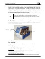
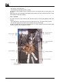
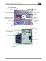
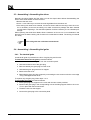
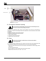
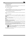
3.1 - The Analyzer
The ISL FP93 5G2 Analyzer is compact and self-contained. It can be globally divided into 2
parts, the control unit and the test unit.
Control unit.
Test unit
Figure 1-1
FP93 5G2 Analyzer.
3.1.1 - Control unit
The Control Unit on the left contains control logic boards, servo motors and also:
In the front side
- The screen,
- The keypad,
- Contrast and brightness adjusting knobs,
- Test flame and pilot light adjusting knobs,
In the back side
- The external link connectors (Printer, RS 232C / Current Loop, ALAN...)
- The mains connector and the ON/OFF switch.
- Gas alimentation nozzle.
In the lateral right side or «Connection panel»
- The connectors of the sample temperature probe, the flash detection device and the igniter.
Page I-17
FP93 5G2 User and Maintenance Manual
DOCV206A001-f
- Gas supply connecting tubes,
- Test and stirring transmission arms housing.
The test arm has a double function: opening the test cover shutter and tip up the igniter in the
test cup.
Both these arms are presented automatically during testing and are retracted into their control
unit housings at the end of testing.
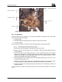
3.1.2 - Test unit
The Test Unit on the right containing the elements specific to the Pensky-Martens flash point
method:
- The heating block - with recess (or well) to receive the test cup - and rapid cooling system,
- The standby support for the test cover (it can also receive the test cup),
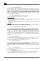
The test cup and test cover with its accessories are, of course, placed in the test unit during test
running. The test cover accessories include :
Test cover and cup
standby stand.
Stirrer rod guide.
é
Test cover shutter.
Sample temperature
probe.
Igniter (electrical).
Flash point detector.
Test cover handle.
Cup handle.
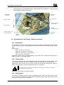
Figure 1-2
The test cover set.
Page I-18
FP93 5G2 User and Maintenance Manual
DOCV206A001-f
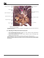
Presentation of the FP93 5G2
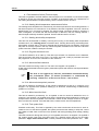
This accessories can be dismantled, thus the electrical igniter can be replaced by a gas one (in the
model allowing this change). Refer to Part 3.
Stirring arm
housing.
Fire detection
Thermofuse
Stirring arm
Test cover handle
Test cup and cover
standby stand.
Test cup handle
Sample
temperature probe
Stirrer rod guide – lefthand screw thread!
Flash point
detector.
Figure 1-3
Test unit.
3.2 - Presentation of the Pensky - Martens elements
3.2.1 - Heating block
A wall heating element provides heating for the metallic test cup well. During testing, the test
cup is placed in this well. An integrated thermocouple measures the temperature in the heating
block.
Heating rates :
- Fast : 12°C/min (+/- 2°C/min)
- Method A : 5.5°C/min (+/-0.5°C/min)
- Method B : 1.25°C/min (+/-0.25°C/min)
- Slow : 3°C/min (+/-0.5°C/min).
Diagnostics can be used to command heating. The red led of the connection panel (Figure 1-5
page I-27) switch on indicating heating
3.2.2 - Cooling system
An air flow is generated by a fan located at the rear of the heating block. The fan takes in fresh
air at the back of the unit and hot air is blown throughout a grid at rear of the heating block.
Performance: With the test cup and cover in place and the sample having been heated to
300°C, the heating block can be cooled down to 50°C in 10 minutes.
Do not block the air circulation outlet behind the heating block and the air circulation
inlet on the read of the test unit.
Diagnostics can be used to command cooling.
3.2.3 - Stirring system
The stirrer is mounted on the test cover. The stepping motor for the stirrer drive arm is located
in the control unit. The drive arm is presented automatically during testing and retracted into its
control unit housing at the end of testing.
Page I-19
FP93 5G2 User and Maintenance Manual
DOCV206A001-f
If the test cover is absent or incorrectly fitted, the stirring system will detect this – according to
the arm position – and indicate this anomaly by an alarm. An audio alarm is triggered and the
test stops.
Stirring speeds :
• 105 (+/-15) rpm - method A,
• 250 (+/-10) rpm - method B,
• 30 rpm – method C,
• None.
Diagnostics can be used to position and retract the stirrer arm and to select the stirring speed
(A, B, C or None).
3.2.4 - Ignition
The type of ignition system is automatically detected and indicated in the test menu screen by a
letter in brackets in the Run Test menu:
- (E) for an electrical igniter ;
- (G) for a gas igniter.
If, when a test is started, no igniter is connected, the test stops.
The connector (See Figure 1-5 page I-27) of the igniter is on the connection panel of the control
unit.
The igniter support and the inclining mechanism are mounted on the cover. Opening the flap
allows the igniter to be lowered into the cover.
The operator may use the «Flame diagnostics» function to : position the test arm, swivel the
igniter, and return the arm (see the chapter Diagnostics and measurements in Part 2).
3.2.4.1. Test flame and pilot light
The test flame lights automatically at the beginning of a test. If the test flame happens to go out,
a pilot light will rapidly relight the test flame, the two flames being in contact in the idle position.
If the test flame and the pilot light are both out, a detection system will light up a glow plug that
relights both flames.
During a test, if the test flame is absent for more than 2 minutes, or if the flame is absent at the
moment of presentation, the test will stop.
Gas supply is controlled by a solenoid valve and the operator may adjust the test flame by
means of a valve screw knob on the front side of the control unit (See Figure 1-4 page I-21).
The SV gas inlet is at the rear of the control unit panel. The test flame igniter is equipped with a
flame detection and ignition device. The igniter arm having been positioned on selecting "Run
Start", if the test flame is not lit immediately, the system will attempt to light it during 10 min. If
after this delay it is not lit, the test is stopped. During test, if the test flame is absent for 1 min or
if it is absent at the moment of a test flame presentation, the test is stopped.
• Gas used : Propane or Butane
: 40 mbar maxi
• Inlet pressure
• Inlet operating pressure : 28 mbar
The gas solenoid valve and the gas flame igniter can be manually commanded for diagnostics.
Page I-20
FP93 5G2 User and Maintenance Manual
DOCV206A001-f
Presentation of the FP93 5G2
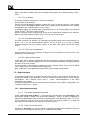
3.2.4.2. Gas flame adjustment
Two knobs in the Analyzer front panel enable the test flame and the pilot light to adjusted.
Pilot light adjusting
knob.
Test flame adjusting
knob.
Figure 1-4
Test flame and pilot light adjusting knobs.
3.2.4.3. Electrical ignition
The glow plug comes on for 10 seconds at the beginning of a test, then goes out. It will come on
again about 30s before each test. The current may be read on the «Test running» screen.
During a test, glow plug current is around 10 A to 13 A. If the glow plug current goes outside
these limits (see Appendix : Defect alarms and indications), the test will stop.
The glow plug and its movement may be manually controlled during diagnostics (see the
chapter Diagnostics and measurements in part 2).
3.2.5 - Flash point detector
The flash point is detected by a thermocouple or a ring-shaped ionization electrode. The flash
detector is mounted on the test cover and either version can be easily disassembled and
reassembled. The flash detector is connected on the control unit panel of the test unit.
Once the flash point has been detected, the test is stopped. The green indicator on the control
unit panel of the test unit (Figure 1-5 -page I-27) illuminates on a flash detection.
When cleaning the test cover after a test, care should be taken not to damage the flash
detection device.
The flash detection threshold of the ring-shaped ionization electrode can be adjusted by
qualified personnel. See the chapter 3
3.2.5.1. Thermocouple detection
All Analyzers are factory equipped with thermocouple flash-point detectors. Ionization ringshaped electrode of detection requires an optional kit.
)
When cleaning the test cover after a test, care should be taken not to damage the flash
detection device.
3.2.5.2. Ring-shaped ionization electrode detection (Ionization ring)
When ring-shaped ionization electrode, the flash detection threshold can be adjusted by
qualified personnel (See Figure 1-5 -page I-27). See also section Flash detection threshold
adjustment of the chapter External operations – Part 3.
Page I-21
FP93 5G2 User and Maintenance Manual
DOCV206A001-f
3.2.6 - Sample temperature probe
The Pt100 platinum temperature probe is placed in a holder in the test cover and is connected
on the near side of the control unit panel of the test unit.
Two types of temperature probes can be used:
• A glass probe.
• A stainless steel probe (optional)
Measuring range : -100 to +400°C (-148 to 752 °F)
3.2.7 - The test arm
In standby, the igniter / shutter operating arm or test arm is located on the control unit Panel
Just like the stirrer arm, it is positioned at the beginning of the test and automatically opens the
shutter at igniter presentation temperatures. The opening movement of the shutter dips the
igniter (gas or electrical) into the test cover opening. The shutter is automatically closed after
presentation of the igniter.
The arm is retracted into its control unit housing at the end of the test.
Presentation and retraction of the shutter operating arm can be manually commanded for
diagnostics (See the chapter Diagnostics and measures – Part 2)
3.3 - The available accessories
• Electrical test igniter kit for Analyzers with a gas one.
• Printer
• A stainless steel sample temperature probe.
3.4 - Software configuration
The non-volatile memory of the Analyzer contains pre-programmed tests (in °C and °F) for all
the standard methods listed in Part I chapter 2 - General scope page I-15.
The standard version of the FP93 5G2 Analyzer is supplied with :
• A diskette containing :
The Service Parameters configuration on leaving the factory,
A PC program for downloading from a host computer uploading from the non-volatile Safe
memory to a host computer of the parameters,
• An external link cable for uploading / downloading.
• ALAN/ RS232 C link adapter.
Page I-22
FP93 5G2 User and Maintenance Manual
DOCV206A001-f
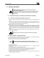
FP93 5G2 system safeties
4 - FP93 5G2 system safeties
All parts of the Analyzer that may come in contact with the operator are not exposed to voltages
exceeding 24 volts (EN 61010-1). The provision of handles permits the test cup and the heating
plate to be removed in complete security. Any malfunctioning will be signaled by an audio
alarm. The origin of fault and report alarms may be displayed.
4.1 - Faults and alarms
4.1.1 - Fire detection
The system is equipped with a fire detector. On detection of fire, the system switches the
Analyzer to standby. A continuous audio alarm is triggered and remains active until the Analyzer
is switched off.
A continuous audio alarm is triggered and the type of alarm can be checked by pressing
(ALARM STOP). Any external alarm/fire extinguishing system connected by the customer will
be triggered by the fire detection fault.
• Commanding of the gas supply SV and the igniter is disabled. To stop the alarm, the
Analyzer must be switched off.
• The user can connect an external alarm device (see the section Connecting an external
alarm device - Part 3). The user can also connect his own fire extinguisher device to the
system security relay. In this case, those devices are also set off.
4.1.2 - Faults switching the Analyzer to standby
Faults presenting a certain risk switch the Analyzer to standby; in this case the "power
consuming units" are switched to standby. The power supply and the gas alimentation are
turned off.
If the detection of those faults (See Alarm list in the Alarm appendix) do
not switch the power consuming units to standby the operator must
switch off the Analyzer and unplug the power supply.
4.1.3 - Faults refusing a test start and stopping a test run
These faults trigger a continuous audio alarm. Press (ALARM STOP) to display the type of
alarm. (See Alarms Appendix)
4.1.4 - Report alarms
A report alarm signals a normal event, e.g. “End of test : flash” or an abnormal event, e.g.
“Flash on first flame test”.
In both cases an intermittent audio alarm is triggered and the red indicator on the keypad is
illuminated. The active pulse of the audio alarm can be set. (See the relevant section of chapter
Configuration: the Analyzer setup menu ("Service parameters" – Part 2 of the current manual.
When the alarm is acknowledged, the indicator is extinguished.
Page I-23
FP93 5G2 User and Maintenance Manual
DOCV206A001-f
4.1.5 - Warning alarms for non conformity correction
This means that the system has had to correct an abnormality in the test run. However, the conformity of
the run is guaranteed after the correction. An intermittent audio alarm is triggered and the warning
number can be displayed by pressing (ALARM STOP). The list of warning numbers is given in the
“Alarms” Appendix.
4.2 - Passwords
There are 3 access levels, level 1 and level 2 require passwords:
Level 0: O-level, for laboratory Operator. Data, information and basic functions are accessible
without entering a password.
Level 1: M-level, for laboratory Manager. Data, information and functions concerning the
calibration
report, quality and operator configuration accessible in access level 1.
Level 2: S-level for Service. Data, information, service functions and technical configuration of
the Analyzer accessible in access level 2.
Level 3: ISL only access level
The selection of access levels is treated in the Access levels and passwords : The « Access »
menu, Part 2.
Once an access level has been confirmed by entering the correct password, it remains available
until the system is explicitly requested to return to an inferior access level. On switching on the
Analyzer, access level 0 is selected by default.
Page I-24
FP93 5G2 User and Maintenance Manual
DOCV206A001-f
Specifications, installation and switching on
5 - Specifications, installation and switching on
5.1 - Characteristics
Physical Dimensions
• Height: 365 mm
• Width: 325 mm
• Depth: 510 mm
• Weight: 30 kg environ
Standards
• ASTM D 93 (A & B)
• IP 34
• NF EN 22719
• ISO 2719
Environment characteristics
: -20 à +50°C
• Storage temperatures
: 10 à 40°C
• Operating temperatures
: 15 à 35°C
• Recommended operating temperatures
Power Supply
• 100-120V et 200-240V à 50 ou 60Hz
• Power Consumption: 700 W maxi
• The non-volatile memory (NvRam) battery life is about 7 to 8 years.
Chauffage
• Heating element : 230/115 V - 630 W
Cooling
Fan : 24 V / 8 W
Allumeur
There are two models of the Analyzer:
• A model with a gas igniter (electrical igniter is optional).
• A model with an electrical igniter.
Gas Supply
• Gas admission pressure: 100 mbar maxi.
: O. D. 10 mm
• Connector
: D5.5 - D3 mm
• SV - test unit silicon gas tubing
• Test unit silicon gas tubing to igniter nozzle : D3.5 - D1.5 mm
• Test unit silicon gas tubing to pilot light nozzle : D3.5 - D1.5 mm
External Link
• Standard Centronics parallel interface for printer
• ALAN Interface
• Service Port
• RS 232C Serial Link with (or without) protocol signals and codes CTS, ENQ, ACK, XON,
XOFF, on 9-pin output (male) connector.
Page I-25
FP93 5G2 User and Maintenance Manual
DOCV206A001-f
Fire Detection
• If fire is detected an audible alarm is activated and the Analyzer switches over to standby.
• A safety relay is provided for connection of a fire extinguishing system and/or an external
alarm. (See chapter Internal operation - Part 3 Maintenance).
• Detection made by thermofuse mounted on the agitation arm: 157°C 250V AC 10A
Temperature Measurement
: Pt 100 probe
• Measuring instrument
: 0 to +400°C
• Range
: available in steps of 20°C / 36°F
• Correction
• Response time equivalent to ASTM D93-A thermometer
LCD Monochrome Graphic Display
: Cold cathode fluorescent
• Backlight
: 320 * 240 pixels, 15 lines of 40 characters
• Resolution
: 120 * 90 mm approx.
• Viewing area
: 0.33 * 0.33
• Pixel size
: adjustable
• Contrast and backlight
• Backlight standby mode : adjustable
Keypad
The screen and keypad are resistant to most chemicals met in the petrochemical industries.
5.2 - After unpacking
Once the Analyzer has been unpacked, it is best to leave it idle in the
laboratory for XX hours (especially if it has been stored at low
temperatures).
• The recommended laboratory temperature is between 15 and 35°C.
• The Analyzer should be placed on a steady horizontal bench top and preferably in a fume
cupboard.
In any case it should be placed in a draught-free place and if possible, in a location that may be
darkened so that the flash point can be observed, if required.
• Allow a minimum clearance of 100 mm at the rear and sides of the Analyzer.
• Protect the Analyzer from all projections of water (see LCD handling precautions further on).
Page I-26
FP93 5G2 User and Maintenance Manual
DOCV206A001-f
Specifications, installation and switching on
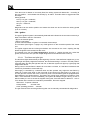
5.3 - Connections
Connector of the flash point
detector.
Red LED
Heating control.
Red LED
Flash point detection.
Sample temperature probe
connector.
Green LED
Gas flame detection.
Adjustment of the flash point
detection threshold for the ring
shaped electrode of ionization.
Green LED
Control of heating block cooling
ventilator.
Igniter connector.
Gas igniter nozzle.
(Flame test)
Heating block cooling air
outlet.
Pilot light nozzle
Figure 1-5
Connection panel.
Service port
for downloads.
ALAN network Inlet and Outlet
ports and a RS232C link by
means of an adapter.
Printer port
Logic card ventilator.
Fuses.
Gas supply nozzle.
Main switcher.
Power supply.
Heating block ventilator.
Figure 1-6
Analyzer rear view.
Page I-27
FP93 5G2 User and Maintenance Manual
DOCV206A001-f
5.3.1 - Gas supply (gas ignition)
• Connect the gas supply to the adapter hose nipple at the rear of the Analyzer. (See la
Figure 1-6 page I-27).
5.3.2 - Connecting the igniter
5.3.2.1. Electrical igniter
Connect the electrical igniter to its connector on the near side of the control unit. (See Figure 15 page I-27).
5.3.2.2. Gas flame
• Connect the flame detection / ignition device to its connector on the near side of the control
unit. (See Figure 1-5 page I-27.
• Connect the tubing for the test flame igniter to its connector on the near side of the control
unit. (Figure 1-5 page I-27.
• Connect the tubing for the pilot light to its connector on the near side of the control unit.
(Figure 1-5 page I-27).
5.3.3 - Flash detector and probe connection
• Connect the flash detector to its connector on the near side of the control unit.
• Connect the sample temperature probe to its connector on the near side of the control unit.
(See Figure 1-5 pageI-27).
5.3.4 - Connecting the printer
Connect the printer to the parallel printer connector (See Figure 1-6 pageI-27) at the rear of the
Analyzer before switching on the Analyzer or the printer. Once the Analyzer and the printer
have been switched on, carry out a link check as described in the chapter
(See section Different diagnostics, chapter Diagnostics and measures : the “Service” menu Part 2). For the printer setup, see section Printer setup of the chapter: Configuration: the
“Analyzer setup” menu, Part 2
5.4 - Handling precautions for the LCD screen
Easily scratched
The LCD is easily scratched. If rubbed by hard objects, the LCD may be damaged. Handle the
LCD with care so as not to scratch it.
Moisture / Water
Electricity fed to an LCD with moisture on its surface may damage it. Gently wipe off any
moisture or let it dry before using the LCD.
Dirt
The LCD can be stained by fingerprints, saliva, starch, oil and fat. If it is stained, gently wipe it
with a soft cloth.
High temperature and humidity
The LCD dislikes high temperature and high humidity. Ensure that the storage and operating
temperatures indicated in Characteristics section of chapter 0 are respected.
Vacuum cleaners
If the work room is cleaned using a vacuum cleaner, keep it away from the LCD (risk of
electrostatic discharge).
Page I-28
FP93 5G2 User and Maintenance Manual
DOCV206A001-f
Specifications, installation and switching on
5.5 - Switching on
Before plugging in the Analyzer and the printer to the mains supply, make
sure that the mains supply matches the specifications on the
identification
plate
at
the
rear
of
the
Analyzer.
Serious damage may result from using an incorrect voltage supply.
Analyzer peripherals, for example the printer and the external link, should
only be connected while the Analyzer and the peripheral equipment are
switched off.
• Switch on the main ON/OFF switch at the rear of the Control Unit (see Figure 1-6 page I-27).
The screen lights up. If not, first check backlight and contrast settings (see Figure 1-7 page I31).
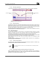
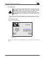
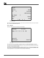
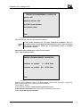
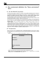
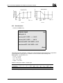
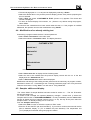
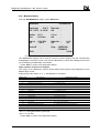
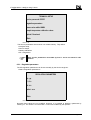
5.5.1 - Switching on display
At switching on the display becomes:
ISL FP93 5G2
Groupe ISL
Z.I. Verson
14790 VERSON
France
www.isl_France.com
Tel.: (+33)2 31 26 43 00
Fax: (+33)2 31 26 62 93
<Espagnol>
<English>
<Français>
<English>
Screen 1-1
Switching on display.
Press the key corresponding to the desired language. The screen displayed is the Run Menu
mode:
Page I-29
FP93 5G2 User and Maintenance Manual
DOCV206A001-f
Sample ID :
Sample No :
EFP :
Next No
°C
Previous No
<TEST START (E)>
Test: 1 D93A(C)
°C
Operator :
<Exit>
<Display>
T : 22.1
A:
<Down>
0
Screen 1-2
Running test display.
The choice of language can be locked in the power-on parameters. Refer to the Part II section
6.5.1 - Power on parameters page II-81.
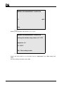
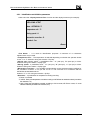
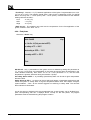
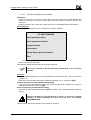
5.5.2 - Auto-test
Selecting <Exit> leads to the following screen display:
ISL FP93 5G2
S / N : 210
Software V 5.1 / V 5.1 © ISL,
2000
Auto test : OK
<Menu Principal>
<Essai P. E.>
Screen 1-3
Initial screen.
The auto-test concerns the PROM, the RAM and the Non-volatile RAM (NVRAM) memories.
If a memory error is detected during switching on, then a test cannot be started until at least the
Analyzer is switched off and on again
If a memory error is detected during the Analyzer switching on, no test can be started. In this
case, try first to switch off the Analyzer and than switch it on again, if the fault is persistent refer
to alarm appendix for more information and eventually troubleshooting.
Page I-30
FP93 5G2 User and Maintenance Manual
DOCV206A001-f
The Analyzer interface
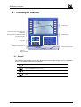
6 - The Analyzer interface
Function keys
STOP, Alarm stop, stop printing and
Reset keys
Numerical pad.
Running test and standby green LED
and alarm red LED.
Arrow keys
Brightness adjusting knob
Contrast adjusting knob
Figure 1-7
Analyzer interface.
6.1 - Keypad
The universal type keypad (no particular language) has been kept simple. It has no alphabetic
keys and no double function keys. It includes:
1
Numerical keys
Backspace (DELETE) Deleting characters.
Point
Dash
Page I-31
FP93 5G2 User and Maintenance Manual
DOCV206A001-f
Function keys:
R
(RESET) Abandons all data entry or quits sample creation/display, page creation/display and
program creation/display.
(PRINT STOP) Stops printing
(ALARM STOP) Displays the triggered alarm. The audio alarm can be stopped, except for fire
detection, in this display.
STOP
ENT
(STOP) Abandons test running - started using "RUN START". No effect on character entry.
(ENT) Confirmation of entry : a letter, text collectively, a value...
Two built-in indicators :
- «Test»: green led,
- «Alarm» : red led,
continuous :
Test running,
intermittent :
Screen in standby mode.
fault, error or report alarms - continuous audio alarm.
Selection keys (on either side of the LCD screen) :
Direct on screen selection of the displayed menus.
Arrow keys:
(UP/DOWN) - (LEFT/RIGHT) arrow keys : selection of letters of alphabet in
editor mode,
(UP/DOWN) - Also used for incrementation / decrementation of digits during
numeric entry,
(LEFT/RIGHT) - Also used for selection of digit position during numeric entry.
The keypad is rendered watertight by a polyester film.
Text entries (sample ID, operator...) are selected from the display. When an entry requires text,
the alphabet and 6 other characters are displayed. Text is then edited as explained in 6.3 - Text
editing page I-33 of the current part.
6.2 - Display
The keypad has a built-in LCD graphic screen. In that way, the displayed functions can be
directly selected using the function keys on either side of the screen . (See Figure 1-7 page I-31
and Screen 1-4 page I-33).
)
Page I-32
In this manual “select” means pressing the relevant key of the indicated
function.
FP93 5G2 User and Maintenance Manual
DOCV206A001-f
The Analyzer interface
Sample ID:
Sample No:
EFP
Next No
:
Previous EFP
<FLAME TEST>
Test
:
Operator :
<Exit>
<Display>
T :TTT.T
A:0
<Down>
Screen 1-4
The example of the run test screen.
6.3 - Text editing
• Select the line directly on the screen (for example "Sample ID", followed by <Other>). The
alphabet is displayed.
• Use the arrow keys (LEFT/RIGHT/UP/DOWN) to select the letter (or character) on the
display,
• Press the (ENT) key - the selected letter is displayed in the "Sample ID" box,
• Select the "Alpha/Edit" function so as to place the cursor for selection of another letter,
• Use the arrow keys again to select the 2nd letter in the "Sample ID" box,
• Etc.
To delete a character in the edit box, use the (BACKSPACE) key or the arrow keys to select the
character and then select <Del>. To insert a character, select <Inser>.
In this way, confirm each character of the desired text. The complete text will be displayed in the
"Edit box" :
• Press (ENT) again to confirm the displayed text collectively.
• The previous display reappears with the text displayed on the initially selected line, e.g.
"Sample ID".
• Press the (RESET) key to abandon editing.
• When the cursor is positioned in the "Sample ID" edit box, digits are entered directly from
the keypad.
6.4 - Entering a numeric value
• Using the corresponding function key to the side of the screen, select the line directly on the
screen (e.g. EFP). The cursor is placed for data entry.
• Use the (LEFT/RIGHT) arrow keys for digit position selection and the (UP/DOWN) arrow
keys to select the digit value. The (BACKSPACE) key is also available or enter the digits
directly from the keypad.
• Display the desired value. Press the (ENT) key to confirm the value.
6.5 - Flip-flop entries
This is the simplest form of parameter setting. It is used in all cases where a limited number of
choices are possible. Examples include : "Y"/"N", "°C"/"°F"... The operator need only press the
key until the desired parameter is displayed.
Page I-33
FP93 5G2 User and Maintenance Manual
DOCV206A001-f
7 - Measurement checks
To ensure that the FP93 5G2 results are reliable, the operator may quickly check the various
readings. These readings should be checked at regular intervals in conformity with the quality
assurance needs of the customer.
7.1 - Temperature measurement
For this operation the operator needs an ISL probe simulator, PS 400. The Analyzer should not
be in "running" mode.
1. Disconnect the temperature probe from its connector (See Figure 1-5 page I-27) and
connect the ISL PS 400 in its place
2. From the run test screen (see Screen 1-2 page I-30) select <Display.>.
3. Set the PS 400 rotary switch on 0°C (32°F).
4. Once the temperature display has stabilized, make sure that the temperature reading is
0°C (32°F).
5. Now position the PS 400 rotary switch on 400°C (752°F) and once the reading on the
display has stabilized, make sure that it is 400°C (752°F).
If calibration is necessary, consult the relevant chapter of the Part 2.
)
The sample probe calibration frequency can be programmed (0 to 365
days). If the calibration frequency is not respected, the operator is
warned on starting a test. It is also possible to disable test starting if the
calibration frequency is not respected. See Part 2 Settings: the “Quality”
menu .
7.1.1 - Temperature probe reading correction
A temperature probe correction function is available. This correction is performed using a
temperature table from 0 to 400°C (32-752°F) at intervals of 20°C (36°F). Refer to chapter
Settings : The “Quality” menu, Part 2. This correction only applies during test runs.
7.1.2 - Response time correction
There is also a function which permits the correction of the temperature probe response time so
that it equivalent to an ASTM Specification E1 thermometer for the Cleveland Flash and Fire
point test. This correction only applies during test runs.
7.2 - Atmospheric pressure measurement
For this check the operator must use a reference barometer.
1. Select "Service" in the main menu.
2. Select "Measures display" to display the current measures of the Analyzer.
3. Check that the "Atmospheric pressure" reading on the display is the same as the
reference barometer reading.
If calibration is necessary, refer to chapter Part 2, Settings : The “Quality” menu chapter, section
Atmospheric pressure measure setting.
Page I-34
FP93 5G2 User and Maintenance Manual
DOCV206A001-f
The flash point test
8 - The flash point test
8.1 - Preparation and procedure
8.1.1 - Sampling
To avoid the loss of volatile material from the sample and the introduction of moisture, do not
open containers unnecessarily and do not make transfers at temperatures above EFP - 17°C
(30°F). Flash point should be the first test performed on a sample.
Samples containing dissolved or free water may be dehydrated with calcium chloride or by
filtering with qualitative filter paper or with a loose plug of dry cotton.
For other sampling practices, see the relevant standard method.
8.1.2 - Preparation
The operator should be familiar with the dangers associated with Flash
Point tests. Some of these dangers are indicated in the form of
"Warnings" in the standard methods.
Dispose of solvents and waste material in accordance with local
regulations.
• Tests should be performed in a draught-free room or compartment. If the Analyzer is
equipped with the anti-draught shield accessory, put it in place before starting the test.
• Make sure that the Analyzer is supported on a level, steady surface.
• Thoroughly clean and dry all parts of the cup and its accessories before starting the test.
Take particular care to avoid the presence of cleaning agents/solvents used after a previous
test.
• Carry out the regular checks as described in the previous chapter 7 - Measurement checks
page I-34 the current Part). See also chapter Calibration: the “Quality” menu.
Page I-35
For other preparation procedures, consult the standard method.
FP93 5G2 User and Maintenance Manual
DOCV206A001-f
8.2 - Test procedure
1. Fill the test cup with the test specimen to the filling mark inside of the test cup. If too much
specimen has been added, use a syringe or similar device to remove the excess.
2. Place the cup in the heating block. The 2 protruding notches of the heating block are used as
guides for the 2 slots on the top rim of the cup.
3. Place the test cover on the test cup.
4. Turn the cover handle clockwise to block the assembly in position. Make sure that the locking
device is correctly engaged.
5. Connect up the flash detector and the sample temperature probe and insert the probe into its
holder in the test cover, if it is not already in its test cover support.
8.2.1 - Selecting a test procedure
Several test procedures are possible:
The user can proceed very quickly by entering only the EFP or eventually by calling back the
previous one. This kind of procedure, assume minimal prior run environment definition (default
values : pressure unit and the test No) – Refer to the section Default values of the chapter
Configuration : the “Analyzer setup” menu –Part 2.
The user can also give more or less information about the test run environment by entering or
selecting the right elements in the given lists (Operator or test names). This other kind of
procedure need a prior “complete” environment definition – Refer to the relevant section of the
chapter Run environment definition: the “Run environment” menu.
The user can create customized tests responding special needs – Refer to the section
Customizing a test of the chapter Run environment definition: the “Run environment” menu.
The user can otherwise enter the Full Mode Run. This mode gives the opportunity of editing or
creating a customized test, by proceeding with an experimental approach, i.e., test sessions
followed, if necessary, by fine adjustments. The resulting program can be saved and called
back for subsequent tests – Refer to the chapter Full mode run – Part 2.
The functional flexibility of the FP93 5G2 Analyzer offers many tests procedures, the user has to
choose the one which corresponds to his needs. The 2nd part of this manual allows, for this
purpose, an exhaustive Analyzer setup information.
Page I-36
FP93 5G2 User and Maintenance Manual
DOCV206A001-f
The flash point test
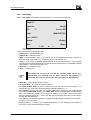
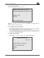
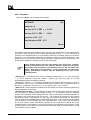
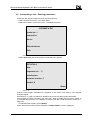
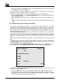
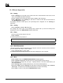
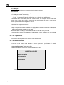
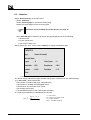
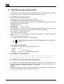
8.2.2 - Test starting
Select <Run menu> from initial screen (see Screen 1-3 Initial screen.PageI-30):
Sample ID :
Sample No :
EFP :
Next No
°C
Previous EFP
Status
<RUN START (E)>
Test : 1 93DA°C
Operator :
<Display>
<Exit>
<Down>
T : 22.1
A:
0
Screen 1-5
Test run screen.
This screen contains following elements:
• «Sample ID :» sample identifier (ID),
• «Sample No :» Sample number,
• «EFP :» expected flash point, if not entered via a pre-programmed sample, the EFP is
entered directly. See section 6.4 - Entering a numeric value page I-33.
• «Test :» Type of test, for example ASTM D93 A/B, IP 34 A/B, NF EN 22719...–The Analyzer
complies with the ASTM D93 A/B, IP 34 A/B, NF EN 22719 and ISO 2719 standard methods
(see chapter 2 - General scope page I-15).
• «Operator :» : Operator's name.
• <Exit> : to main menu.
)
The sample ID, the type of test and the operator name can be preprogrammed. On selecting one of these functions, the operator is
presented with a list. He should select one item from the displayed list.
• «Next No» : increment the sample number.
• «Previous EFP» : for using the previous test EFP
• The "RUN START (E/G)" function is used to start the test selected on the screen. If no
igniting device is connected, the field between brackets still blank «( )».
• The <Display> (Screen 1-5 page I-37) function switches the Analyzer to the 4-digit sample
temperature "TEST RUN" display. This "TEST RUN" screen is automatically activated at test
start. The temperature display can be read at a distance of 5 meters. The expected flash
point, the Analyzer status (e.g. "Test"), the date, the time and the glow plug current (when it
is used) are also displayed.
• The <Down> key allows the operator to display the page numbers allocated to the results «In Spec» and «Out spec».
• The temperature, "T", and the no. of igniter applications, "A", are displayed at the bottom of
the screen. These values evolve during a test.
Page I-37
FP93 5G2 User and Maintenance Manual
DOCV206A001-f
)
The run mode screen can be set to display and give access only to
certain functions. Refer to the section Customizing the run mode screen
of chapter Run environment definition : the “Run environment” menu Part 2.
A number of "Entry" options are available using the function keys on the side of the screen.
1. Select "Sample ID" and then select one of the pre-programmed sample names proposed.
2. Select "Operator" and then select one of the pre-programmed operator names proposed.
3. Select "Test" and then one of the pre-programmed tests proposed.
4. Select "Sample No". Enter the sample number as explained in "Entering text and numeric
values" of this chapter. It is possible to use the "Next No" function so as to increment the
sample no. used for the previous test
5. Select "EFP" and enter the Expected Flash Point as explained in the "Entering a numeric
value" section of this chapter. Press (ENT). It is also possible to use the "Previous EFP"
function so as to reselect the EFP for the previous test run.
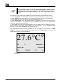
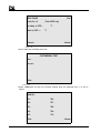
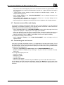
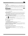
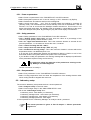
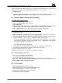
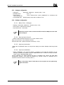
If the apparatus has been correctly prepared, you are now ready to start a test run. A "RUN
START ( )" function is provided for this purpose. When, the "RUN START ( )" function is
selected the following screen is displayed:
27.6°C°
EFP :
°C
Applications: 0
Analyzer : Idle
<Exit>
<Flame test>
17/04/2000
17:31
0,1A
Screen 1-6
Test run screen.
Page I-38
FP93 5G2 User and Maintenance Manual
DOCV206A001-f
The flash point test
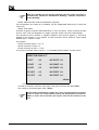
8.3 - Test running
The test running screen gathers the following information :
EFP : Expected Flash Point. The EFP may be modified during a test (Screen 1-6 page I-38) or
during a test in the test running screen (Screen 1-5 page I-37).
Status : Current status of the Analyzer. Here is a table with the significance of the « Status »
field:
Field value
« Idle»
« Rotation »
« Ignition»
Significance
The apparatus is in standby.
The sample changer is being positioned - only when the accessory is installed.
Glow plug ignition for about 10 seconds
Flame test lighting which continues until the test flame is lit (respecting the limits
imposed by the "No test flame" fault alarm).
Preheating phase of program for solid or viscous samples.
The phase before the temperature the first presentation of the igniter
The temperature for the first presentation of the igniter has been reached.
Automatic presentation of the igniter.
Preheating
« ----> Tests »
Tests
« Presentation»
Applications : the number of applications of the igniter.
<Flame Test> to present the igniter (at any time) during a test run
<Fin> back to test run screen.
The date, the time and the intensity of the glow plug current.
During the igniter application, the great size temperature display is locked. The displays will be
unlocked only if the flash point has not been detected. Thus, if the flash point is detected, the
detection temperature will still displayed after the test automatic stop.
8.3.1 - Igniter check after pressing "RUN START":
If a test flame is being used as igniter, check its diameter. To adjust the test flame to a diameter
of 3.2 to 4.8 mm (5/32") (according to standards). If necessary, use the setting knob in the front
side of the control unit (Figure 1-4 page I-21).
)
If the gas flame should go out unexpectedly, gas may infiltrate the space
above sample in the cup. This infiltration could falsify the test result.
8.3.2 - Manual test stop
The test can be stopped manually at any time during a test run:
1. Press the keypad (STOP) key.
2. Confirm the current test stop by selecting « Ok » at screen.
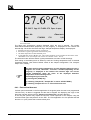
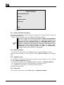
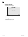
8.4 - Standard test stop
When the Flash Point is detected, an intermittent audio alarm is triggered. To stop the alarm
press the «STOP ALARM» button on the keyboard. The “End of test” screen will be displayed.
Select <Quit>. Quitting gives a screen that is similar to the “Test running” screen and is called
the “End of test” screen:
Page I-39
FP93 5G2 User and Maintenance Manual
DOCV206A001-f
27.6°C°
EFP : 50.0°C App :10 FLASH : 27.6 Spec : In spec
Status : Idle
<Exit>
<Flame test >
17/04/2000
17:31
0,1A
Screen 1-7
End of test screen.
The flash point temperature remains displayed when the test is stopped. The results,
observed/corrected/rounded (depending on the program), is displayed to the nearest first
decimal digit. On the first line below the large "Sample temperature display" are displayed :
1. the EFP at the first automatic igniter presentation,
2. the number of igniter applications until the flash point,
3. "FLASH" temperature of detected flash point.
4. a result indicator for the "In spec" test. The result information is also available at the bottom of the
"Test start" screen. (See chapter Test results: the “Results” menu – Part 2).
The stirrer drive arm and the shutter / igniter presentation arm return to their housings.
Fast cooling of the heating block is started up until the "Cooling temperature limit" is reached
(Parameter setting). (See section Default values of the chapter Configuration: The “Analyzer
setup” menu, Part 2,).
)
The flash and fire point temperatures are still displayed when the test is
stopped. The result, observed / corrected / rounded (depending on the
program), is displayed to the nearest first decimal digit. the current
sample temperature takes the place of the displayed detection
temperature in the following cases:
At the beginning of a new test,
by pressing the (STOP) key,
by selecting "Sample ID", "Sample No" or menu <START RUN>),
by selecting "Prepare the run" or "End of full mode run»
8.4.1 - Flash on first flame test
If a flash point is detected on the first application of the igniter (when the test is not programmed
"GO-NO GO"), an alarm is triggered and the test is stopped. On displaying the origin of the
alarm the operator will know that a "Flash on first flame test" has been detected.
In this way the operator may repeat the test with a fresh specimen of the sample, using the
erroneous flash point temperature as the EFP. The first application for the repeated test will
thus be 17°C (30°F) below the erroneous flash point.
Page I-40
FP93 5G2 User and Maintenance Manual
DOCV206A001-f
The flash point test
8.4.2 - Flash point detection before the standard phase
If the flash point is detected before the standard phase, the test that is running stops and the
abnormal flash detection is triggered.
8.5 - Cleaning the test set
)
The recommended safe handling temperature is below 55°C (130°F).
The operator can remove the test cover and the cup :
• Turn the handle of the test cover anti-clockwise to unlock it.
• Remove the cover (with the probe in its holder) and place it in the standby holder provided.
• Carefully remove the cup and its contents.
• Clean the cup, the test cover and all accessories with a suitable cleaning agent. In general,
all dirty accessories, including the test flame nozzle, that might affect the test run result
should be cleaned.
Do not use cleaning solvents near a flame.
8.6 - Test cover and accessories cleaning
• Depending on the state of the different accessories, they may be disassembled for a through
cleaning. (Refer also to the 3rd Part 3 of the current manual).
• Disconnect the temperature probe from the Analyzer connection panel and unscrew the
knurled flange which fixe it to the test cover, then remove it carefully.
• Pull the shutter locking ring (in the center of the cover) upwards and pull the shutter to the
side at the same time to remove it.
• It is usually possible to clean the flash point detected without dismantling it. If you do so,
handle it carefully and make sure that the ionization flash detection ring still concentric to the
cover on reassembling. If the flash detection probe must be is removed for cleaning refer to
Part 3 of the current manual.
• Clean the cup, the test cover, the test cover shutter, the stirrer set, the flash point detector
and the temperature probe.
• Assemble the test set (the test cover and its accessories) for the next test.
The test set standby stand can also be Cleaned.
If it is necessary to dismantle the stirring set or the flash point detector refer to the 3rd part of the
manual.
Page I-41
FP93 5G2 User and Maintenance Manual
DOCV206A001-f
9 - Regular maintenance
Specific time intervals are not given for these checks. In fact the ideal time intervals depend on
the Analyzer environment, frequency of use and the customer's Quality Assurance needs. The
following conditions should be taken into consideration when deciding the regular maintenance
time intervals.
• Ambient temperature above 25°C (77°F).
• A number of different Analyzer operators.
• Dirty or dusty ambient air.
• The Analyzer is operated during multiple shifts each day.
The optimal time interval will only come from experience.
Here is a list of checks and possible maintenance operations.
1. Adjustment of the test flame : check at the beginning of the test and if necessary adjust by
means of the valve setting knob.
2. Temperature measurement check at regular intervals (see chapter 7 - Measurement
checks page I-34).
3. Atmospheric pressure measurement check (see chapter 7 - Measurement checks page I34).
4. The cup, the flash detector, the temperature probe, the flame nozzle and the test cup
should always be clean. Refer to the previous section. Dismantle the cover for a periodic in
depth cleaning. Refer also to the Part III of the current manual.
5. Real time clock setting (refer to the Part II section 6.7 - page II-82).
6. Temperature probe replacement. Refer to the Part III of the current manual.
7. Flash detector replacement. Refer to the Part III of the current manual.
8. Glow plug replacement. Refer to the Part III of the current manual.
9. Regular uploading of the service parameters (refer to the Part II section 6.3 - Service:
service parameters page II-76)
10. Printer paper/ink ribbon replacement. See printer manual.
Page I-42
FP93 5G2 User and Maintenance Manual
DOCV206A001-f
Part II
Advanced use of the FP93 5G2
Page intentionally blank.
Page II-44
FP93 5G2 User and Maintenance Manual
DOCV206A001-f
Generalities
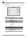
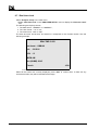
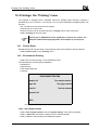
1 - Generalities
This part deals with the advanced use of the FP93 5G2, i.e. the setting of the device according
to the needs of the user. As previously indicated, this presupposes that the user is familiar with
the techniques of plugging tests.
The FP93 5G2 settings are accessible from the main menu (see the following chapter).
DOCV206A001-f
FP93 5G2 User and Maintenance Manual
Page II-45
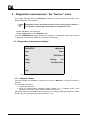
2 - The main menu
The main menu can be acceded from the initial screen (Select <Exit> from the test run screen –
see Part 1):
MAIN MENU
Quality
Full mode run
Runs environment
Last run result
Service
Printing
Analyzer setup
Results memory
<Access>
<Exit>
Screen 2-1
Main menu.
This menu gives access to the following functions:
Functions
Content
Quality
Temperature measurement calibration
Next calibration date
Probe correction table
Atmospheric pressure calibration
Programs, samples, operators and result pages edition.
Program, sample, operator and result lists display.
Customizing run mode screen
Current measures and diagnostics
Configuration:
Printer
External link - ALAN or RS232C
Service:
Level 2 access password
Regulation parameters
Buzzer pulse width
Upload / Download
ISL settings (access level 3)
Default values
Laboratory setup
Real time clock
Entering password for a given access level
Preparing/ exiting the full mode run.
Displaying, printing and transferring the last test result.
Initializing the printer
Service printings:
Internal parameters
Statistics
Displaying, printing and transferring a result.
Displaying the result pages allocation
Pages cleanup
Run environment
Service
Analyzer setup
<Access>
Full mode run
Last run result
Printing
Results memory
Page II-46
FP93 5G2 User and Maintenance Manual
Access
level
DOCV206A001-f
Calibration: the « Quality »menu
3 - Calibration: the « Quality »menu
To ensure the reliability of the test results it is possible to quickly verify the measures of the
Analyzer (refer to the relevant section of Part 1). Those checks must be done at regular time
intervals. If a calibration is needed, a PS 400 Probe simulator is necessary. To achieve those
operations, follow the instructions of following sections.
Select “Quality” in the main menu.
QUALITY
Temperature measurement calibration
Next calibration date : JJ/MM/AA
Probe correction table
Atmospheric pressure calibration
<Exit>
Screen 2-2
)
DOCV206A001-f
Calibrations cannot be performed during test running..
FP93 5G2 User and Maintenance Manual
Page II-47
3.1 - Sample temperature measurement calibration
Select “Sample probe calibration” in the “Quality” display.
TEMPERATURE MEASUREMENT
Temperature measure calibration
Calibration frequency : 30 days
Next calibration date
: JJ/MM/AA
Start test refusal
:N
<Exit>
Screen 2-3
For calibration of the sample temperature measurement, the sample temperature probe must be
disconnected and replaced by an ISL probe simulator PS 400.
Disconnect the temperature probe (see Part I section 5.3 - Connections page I-27) and connect
probe simulator.
Select “Temp. measure calibration” of TEMPERATURE MEASUREMENT screen.
Page II-48
FP93 5G2 User and Maintenance Manual
DOCV206A001-f
Calibration: the « Quality »menu
TEMPERATURE MEASUREMENT CALIBRATION
Operator : OP1
Calibration reference : REF
Use 0-400°C probe simulator
Use resistance values
<Exit>
Screen 2-4
Enter the operator name and the calibration reference.
)
If the probe simulator has not been guaranteed 0°C/400°C, then its
resistance values should be guaranteed and their exact values must first
be entered. Resistance values can be guaranteed by ISL or another
authorized company.
Resistance Values Guaranteed - Entry of exact values
Select “Use resistance values”.
TEMPERATURE MEASUREMENT CALIBRATION
Resistance on position
0 : 100.00 Ohms
Resistance on position 400 : 247.06 Ohms
<Exit>
Screen 2-5
Enter the exact resistance values, to 2 decimal digits, opposite “0°C” and 400°C. Typical ISL
probe simulator values are indicated in the above display.
Press <OK> to confirm.
Continue as described for "Probe simulator guaranteed" below.
Probe Simulator Guaranteed (the ISL PS 400 is guaranteed 0 and 400°C)
Select “Use 0-400°C probe simulator”
DOCV206A001-f
FP93 5G2 User and Maintenance Manual
Page II-49
TEMPERATURE MEASUREMENT CALIBRATION
0°C
400°C
<Exit>
Screen 2-6
Position probe simulator rotary switch on “0°C / 32°F”
TEMPERATURE MEASUREMENT CALIBRATION
Position probe simulator rotary switch on 0°C / 32°F
Temperature : 0.X
A/D : CCCCC
<OK> When reading in stable
Screen 2-7
Position the rotary switch on 0°C and wait until the “Temperature” and “A/D” readings are
stable.
Once the readings are stable, press <OK>.
Page II-50
FP93 5G2 User and Maintenance Manual
DOCV206A001-f
Calibration: the « Quality »menu
The previous display reappears.
This time, select “400°C” and the display becomes :
TEMPERATURE MEASUREMENT CALIBRATION
Position probe simulator rotary switch on 400°C / 752°F
Temperature : XXX.X
A/D : CCCCC
<OK> when reading in stable
Screen 2-8
Position the rotary switch on 400°C and wait until the “Temperature” and “A/D” readings are
stable.
Once the readings are stable, press <OK>.
3.2 - Periodicity and test start refusal
• Select “Calibration frequency” and enter the periodicity for the performance of calibrations
in days (0 to 365). (0 means that there is no periodicity programmed.)
• Use the “Start test refusal” key to select “Y” for yes or “N” for no. If this parameter is set at
“Y”, then a test cannot be started unless sample probe calibration is performed within the
period defined for “Calibration frequency”.
3.3 - Probe correction table
• Select “Quality” in the main menu and then select “Probe correction table”.
PROBE CORRECTION TABLE
Title :
Temp unit :
°C
Correction : (Reference – Probe value)
* Please respect temperature unit *
<Edit table>
<Exit>
Screen 2-9
DOCV206A001-f
FP93 5G2 User and Maintenance Manual
Page II-51
)
Note the reminder on the display indicating that the probe correction is
calculated by: (Reference Thermometer Reading) - (Sample Temperature
Probe Reading)
• Select “Title” and enter a title for identification purposes.
If the temperature unit needs to be modified, use the “Temp unit” flip-flop key to select the
correct unit.
• Select <Edit Table>
There are 21 probe correction values between 0°C / 32°F and 400°C / 752°F (inclusive) in steps
of 20°C / 36°F. They are displayed on 2 pages, press the <Down> key for the second page.
The corrections can be positive or negative. Negative ones must be signed (-). All can be
entered to the nearest 0.1 of a degree. A linear correction will be made for values falling
between the 21 correction values.
For example :
• Probe correction at 80°C = +0.1°C
• Probe correction at 100°C = 0
• Probe correction at 120°C = -0.2°C
At 110°C the corrected value is 109.9°C , i.e. calculated linearly between 100 and 120°C.
CORRECTION TABLE IN °T
0°C/32°F
: 0.0
100°C/212°F : 0.0
20°C/68°F
: 0.0
120°C/248°F : 0.0
40°C/68°F
: 0.0
140°C/284°F : 0.0
60°C/140°F
: 0.0
160°C/320°F : 0.0
80°C/176°F
: 0.0
180°C/356°F : 0.0
<Down>
Screen 2-10
• To enter a correction, select the value, type in the probe correction and press (ENT).
• For values on the second page, press <Down>.
)
Page II-52
If the sample temperature is below 0°C (32°F), the temperature correction
at 0°C is used. If it is above 400°C (752°F), the temperature correction at
400°C is used. This correction will only be valid for the duration of the
test.
FP93 5G2 User and Maintenance Manual
DOCV206A001-f
Calibration: the « Quality »menu
3.4 - Atmospheric pressure measurement calibration
To calibrate the atmospheric pressure measurement circuits, a reference barometer is needed.
• Select “Quality” in the main menu and then select “Atmospheric pressure calibration”.
ATMOSPHERIC PRESSURE CALIBRATION
(Measured atm. pressure :
763.7 mmHg)
101.8 KPa
Atmospheric pressure 101.3
Pressure unit : KPa
<Exit>
Screen 2-11
The pressure reading from the reference barometer can be entered in mmHg or kPa. First
select the pressure unit.
To modify the pressure unit (kPa/mmHg), select “Ext. pressure unit” (flip-flop selection).
Select “Ext. barometer pressure” and enter the reading taken on the reference barometer. The
pressure measured by the Analyzer is displayed at the top of the screen.
The reference pressure can be entered using either unit (kPa/mmHg). Do not confuse the
pressure unit used for entry of the reference barometer reading with the pressure unit display
configuration. The display unit is set using "Power on parameters" of "Run default values".
(See chapter Configuration : Analyzer setup menu).
DOCV206A001-f
FP93 5G2 User and Maintenance Manual
Page II-53
4 - Run environment definition: the “Runs environment”
menu
4.1 - The “ISL FP93 5G2” test principle
A FP93 5G test program consists of a number of test guideline parameters and a sample ID.
The guideline parameters and the sample ID are saved in a "Test" numbered from 1 to 20. In
general, the guideline parameters depend on the type of sample being analyzed. These
parameters are defined in the various standard methods (for example ASTM D 93 A/B, IP 34...).
It is also possible to create a test which does not correspond with a standard method.
The test program range of the ISL FP93 5G Analyzer on leaving the factory includes all the
standard methods listed in chapter 1, ASTM, IP, NF, EN, ISO.
The customer can of course replace, by his own personal test programs, the test programs he
does not require. The other advantage of the FP93 5G2 is that the customer can update the test
programs himself when the standard methods are modified, without having to wait for a
software update.
Having created test programs corresponding with the various standard methods and nonstandard test programs, a number of sample families - from 1 to 20 - may be created. To each
sample family may be associated a test program. Once the sample family has been edited, it
must be saved using a specific sample storage number which is selected from a displayed list.
In this way, when the sample ID is selected, during "Fast Mode" operation, the associated test
will then be summoned. Edition of samples is treated further on.
4.2 - Test parameters
Before using the function "Customize a test" of "Runs Environment" for test program creation,
let us first display a pre-programmed test to discover the parameters and information contained
in a "Test".
• Select "Display a test" in the "RUNS ENVIRONMENT" submenu.
TEST DISPLAY
Selected test: _
Show tests list
<Display selected test>
<Exit>
Screen 2-12
• Select "Show tests list" and the list of existing tests are displayed (1 to 20).
• Select one of the pre-programmed tests, for example "T01 : 1 D93A (C) (C°)". The above
display returns. The "Selected test" entry reads "1".
Page II-54
FP93 5G2 User and Maintenance Manual
DOCV206A001-f
Run environment definition: the “Runs environment” menu
4.2.1 - Identification and definition parameters
• Now select the <Display Selected Test> function and the display becomes (for example) :
DISPLAYING A TEST
Name : ASTMD93A °C
Temperature unit : °C
Stirring speed : A
Barometric correction : O
Rounded : Yes
<Down>
Screen 2-13
«Test Name» : It is used for identification purposes. A maximum of 12 characters
alphanumeric may be used.
«Temperature Unit» : The temperature is selected depending on whether the operator wishes
to use °C or °F. Selection during test creation : Flip-flop.
«Stirring rate» Stirring speed : 3 possibilities exist - "A" (105 rpm), "B" (250 rpm) or None.
Selection during test creation : flip-flop type
«Stirring speed» :3 possibilities exist - "A" (105 rpm), "B" (250 rpm), “C” (30 rpm) or None.
Selection during test creation : flip-flop type
«Barometric correction» : It is possible to automatically correct the thermometer readings for
the calculation of results. "Y" for yes and "N" for no. This correction is in accordance with the
ASTM D93-00 standard method.
Selection "Y" or "N" during test creation : flip-flop.
«Rounded» : 3 possibilities for temperature reading rounding:
ª "None": no rounded
ª "ASTM": Flash point temperature rounded according to ASTM D93-00 standard method (rounded to
the nearest 0,5 °C)
ª "ISO": Flash point temperature rounded according to ISO 2719-88, NF EN 22 719-94, IP 34-99
standard methods (rounded to the nearest 0,5°C).
DOCV206A001-f
FP93 5G2 User and Maintenance Manual
Page II-55
4.2.2 - Fast phase
• Press the <Down> key to display the next page.
FAST PHASE
<Up>
Heating rate : A
Test every 10.0°C if ERP < = 110.0°C
Test every 10.0°C if ERP >
110.0°C
Start of test at XX - YY°C
End of fast phase at ERP - YY°C
<Down>
Screen 2-14
This phase is optional and provided for those operators who wish to start the test rapidly and/or
who wish to apply the ignition source before the temperature (EFP - 17 °C for ASTM D93 A)
specified in the standard method. It is particularly interesting for heating samples, that have a
high EFP, to the temperature indicated in the standard method for the first application of the
ignition source. It can also be used to rapidly determine an approximate EFP for a sample. This
phase can be disabled by selecting "none" for the heating rate.
)
The 2 heating phases can have same heating rate. In this way, a uniform
heating rate will be kept for the 2 phases, but the frequency of the igniter
presentation will be different. The minimum value for the end of the fast
phase - before the first presentation - is thus disregarded. The fast phase
igniter presentations continue until the beginning of the start of the
standard phase.
“Heating rate” : 3 possibilities exist ; "None" disables the fast phase, A = 5.5 °C/min and "High"
= 12 °C/min. Selection during test creation : flip-flop type. See next page for the fast
phase/standard phase combinations allowed.
“Test every”: Interval in °C (°F) between applications of the igniter. Minimum value is 2°C (5°F)
and maximum value is 10°C. The operator should enter a value for the 2 categories of EFP. In
the case of ASTM D93 A & B, they are =< 110°C (230°F) and > 110°C (230°F).
“Start test at”: If the fast phase is enabled then the operator can enter here the temperature for
the first application of the igniter.
“End fast phase at EFP- ”: The temperature at which the fast phase ends should be such that
the next phase, the standard phase, begins correctly - i.e. in accordance with the conditions
outlined in the standard method being used. The value of this program parameter depends on
the heating rate combinations used for the test . The minimum limit values for this program
parameter are given in the table on the next page. The operator should add the "start test at"
value entered for the standard phase corresponding limit value. A correct value must be entered
so as to obtain the correct heating rate at the first presentation. In any case, if the fast phase is
too long the system will be automatically regulated so as to respect the heating rate of the
"standard phase". If the operator is not sure of the value to be obtained to be entered, it is best
to leave it blank and the value will be calculated automatically. Refer to the table Table 2-1 page
II-57 and also the curves below.
Page II-56
FP93 5G2 User and Maintenance Manual
DOCV206A001-f
Run environment definition: the “Runs environment” menu
Curve 1
Curve 2
4.2.3 - Standard phase
• Press the <Down> key.
STANDARD PHASE
<Up>
Heating rate : A
Test every 2.0°C if EFP < = 110.0°C
Test every 2.0°C if EFP >
110.0°C
Start of test at EFP - XX°C if EFP <= 110°C
Start of test at EFP - XX°C if EFP > 110°C
<Down>
Screen 2-15
This phase sets the parameters ; heating rate, interval between igniter applications, temperature
of first application of the igniter in accordance with the standard method being used.
Heating rate : 4 possibilities exist :
• "Low" = 3 °C/min
• "A" = 5.5 °C/min
• "B" = 1.25 °C/min
• "High" = 12 °C/min
Selection during test creation : flip-flop type.
Fast Phase
Standard Phase
None
Low
None
A
None
B
None
High
High
Low
High
A
High
A
A
B
High
High
A
A
End of fast phase
45°C
35°C
45°C
15°C
0°C
0°C
Min. Limit values
80°F
64°F
80°F
27°F
0°F
0°F
Table 2-1 : Heating rate possible combinations and fast phase limit values.
DOCV206A001-f
FP93 5G2 User and Maintenance Manual
Page II-57
“Test Every”: Interval in °C (°F) between applications of the igniter. Programmable from 0.5°C
(1°F) to 10°C (18°F). The operator should enter a value for the 2 categories of EFP. For ASTM
D93 A & B, they are =< 110°C (230°F) and > 110°C (230°F). Interval values fort the different
heating rates are as follow :
: 0.5°C (1°F)
• Low
: 1°C (2°F)
• A/B
: 2°C (5°F)
• High
“Start test at” : The operator can enter here the temperature for the first application of the
igniter, entered in form "EFP - XX°T".
4.2.4 - Final phase
• Press the <Down> key.
FINAL PHASE
<Up>
Go - No Go : N (Only one test at EFP)
Pre-safety at TP + : XX°C
Flash safety at EFP + : YY°C
Fire safety at EFP + : ZZ°C
<Exit>
Screen 2-16
GO-NO GO : Only 1 presentation of the ignition source is allowed by setting this parameter to
"Y", for yes. If more than one presentation of the igniter should be allow (as described in the
usual standard methods), then select "N" for no. If this parameter is "Y", the test start
temperature is ignored. Selection during test creation : flip-flop.
Pre-safety Alarm at EFP + : A pre-safety (intermittent) alarm can be set for given temperature
above the EFP.
Safety Alarm at EFP + : An alarm can be set which will trigger a intermittent audio alarm and
switch the system to "safety state" at a given temperature above EFP. See chapter "Analyzer
system safeties" – Part 1 for the actions triggered on switching to safety state. The red fault
alarm indicator is illuminated.
As can be seen on displaying this pre-programmed test, a test program can be divided into 4
parts corresponding with the 4 displays above. Except for the fast phase, all program
parameters must be entered during test program creation.
Page II-58
FP93 5G2 User and Maintenance Manual
DOCV206A001-f
Run environment definition: the “Runs environment” menu
4.3 - Customizing a test : Entering parameters
Creating a new program needs the level 1access password.
• Select "Runs environment" in the "Main Menu".
• Select the submenu "Customize a test". The display becomes :
CUSTOMIZE A TEST
Selected test : 1
Show tests list
New one
<Edit selected test>
<Exit>
Screen 2-17
• Select "New one" and the first page for parameter entry appears :
TEST DETAILS
Name :
Temperature unit : °C
Preheating time :
Barometric correction : Y
Rounded : N
<Down>
Screen 2-18
Enter the test program parameters as explained in the section Text editing –The Analyzer
interface chapter.
See section 4.2 - page II-54 above for definitions of the various test program parameters.
3 more pages of entries are made in the same way : either by editing text or numeric values, or
by using flip-flop type keys. The 4 displays correspond with the 4 parts described in section 4.2 page II-54.
• To abandon test creation, press (RESET).
When all entries have been made, and with the "FINAL PHASE" screen is displayed :
DOCV206A001-f
FP93 5G2 User and Maintenance Manual
Page II-59
FINAL PHASE
<Up>
Go-No Go : N
(Test at EFP only)
Pre-safety at EFP +
Safety at EFP + :
°T
°T
<Cancel>
<Down>
Screen 2-19
• Press <Ok> and the display becomes :
CUSTOMIZING A TEST
Save
Save as...
<Exit>
Screen 2-20
• Select "SAVE AS" and the list of already existing tests are displayed (from 1 to 20) as
follows :
SAVE AS...
T01 :
T06 :
T02 :
T07 :
T03 :
T08 :
T04 :
T09 :
T05 :
T10 :
<Exit>
<Down>
Screen 2-21
Page II-60
FP93 5G2 User and Maintenance Manual
DOCV206A001-f
Run environment definition: the “Runs environment” menu
• The second page (test no. 11 to 20) can be displayed by selecting <Down>.
• Select the desired test no. key and the previous display (Screen 2-20) returns proposing the
test no. selected.
• Select <Exit> the screen «CUSTOMIZE A TEST» (Screen 2-17) appears. The chosen test
number is displayed.
• To return to the first display of this section, 4.3 - (Screen 2-17) without saving the program,
select <Exit>.
The test that was created has thus been saved under this test no. If the program is modified
afterwards, the operator can save the modifications using "SAVE".
4.4 - Modification of an already existing test
Customizing a program needs the level 1 access password.
• Select "Runs environment" in the main menu.
• Select the submenu "Customize a test". The display becomes :
CUSTOMIZE A TEST
Selected test: 1
Show tests list
New one
<Edit selected test>
<Exit>
Screen 2-22
• Select "Show tests list" to display the list of existing tests.
• Select the test to be modified and the previous display returns with the no. of the test
displayed in the "Selected test" line.
• Select <Edit selected test> and the test is displayed.
Modification and saving of the existing test are performed in the same way as program creation,
described in section 4.3 - Customizing a test : Entering parameters page II-59. It may be saved
under the same test no. using "Save" or a new test no. using "Save As".
4.5 - Samples edition and display
The "raison d'être" of sample families has been evoked in section 4.1 - : The “ISL FP93 5G2”
test principle page II-54.
To create or edit a sample, the operator (laboratory manager - access level 1) selects the
"Samples edit" function of "RUNS ENVIRONMENT". He may immediately use the <Show List>
function to display the list of sample numbers (from 1 to 20). He may at this point select the
sample number - an already existing one or a free one.
From the "Samples edit" display:
• Select the <Edit> function to switch the system to "Edit" mode
• Enter the ID and the EFP (20-350°C/70-660°F). If you wish to continue the test until the fire
point is detected, display "Y" ("N" to disable fire point detection). The temperature unit
(°C/°F) displayed is selected during test program creation.
DOCV206A001-f
FP93 5G2 User and Maintenance Manual
Page II-61
• Enter the "In-spec" and "Out-spec" pages. The "Out-spec" page may be the same page as
the "In-spec" or it may be the page 21.
The user must now save the sample he has just edited. The principle is the same as that
described in section 0 above for saving a test program.
Just as it is possible to display a test, it is also possible to display an edited sample.
• Select "Samples display" of the "RUNS ENVIRONMENT" menu to display the sample in the
memory (if there is one).
• Select <Show List> to display the list of samples. (There are 2 pages, press <Down> for the
2nd.)
• Select the sample to be displayed and the previous screen reappears displaying the selected
sample.
4.6 - Specification pages editing and display
The access to results pages needs level 1 access password. Results pages from 1 to 20 are
reserved for the pre-programmed samples. (A results page 21, which can receive a maximum of
50 results, also exists.) Flash point result specifications can be edited for pages 1 to 20. In this
way, an upper and a lower results limit can be associated with the results page of any preprogrammed sample. This associated page is selected during "Samples edition" (see section
4.5 - Samples edition page II-61).
Flash result specification page editing consists of entering 2 results values, upper and lower
limits. When a test run is performed using a pre-programmed sample, the result (observed,
corrected or rounded depending on the test configuration) is compared with the upper and lower
limits.
If the result is within the specifications ("In spec") for the results page, then it is recorded in this
page.
If a result of a pre-programmed sample is "Out of spec" it is stocked in the page defined during
"Samples editing". If there is no specified page, the result in stored in page 21 – this page is
the “Out of spec” results storage default page.
Select "Pages edit" of the "RUNS ENVIRONMENT" menu to display an "Output page". From
this display, the list of "Output pages names" can be displayed by pressing <Show List>.
OUTPUT PAGES EDIT
No :
<Show list>
Title :
( 0 storage still available )
Spec Min:
Spec Max:
Storage:
25 results
<Exit>
<Edit>
Screen 2-23
To display an existing page, use the <Show List> function and then select the page no. The
specification page reappears filled out.
• Select the <Edit> function to switch the system to "Edit" mode. (<Edit> becomes <Ok>.)
• Enter the title, the mini. and maxi. specification result values and the maximum number of
results that can be saved on the page. For details on the latter entry see chapter 11 - Results
and printing: the “Results memory” menu page II-89.
Page II-62
FP93 5G2 User and Maintenance Manual
DOCV206A001-f
Run environment definition: the “Runs environment” menu
• Once all the entries are displayed, press <Ok> and save the entries in a page between 1 and
20. The principle is the same as that described in section 4.3 - page II-59 above for saving a
test program.
• "Pages display" follows exactly the same principle as "Samples display » section 4.5 Samples edition page II-61 :
• Select "Pages display" of the "RUNS ENVIRONMENT" menu to display the page in the
memory (if there is one).
• Select <Show List> to display the list of pages. (There are on 2 screen displays for the
complete list, press <Down> for the 2nd page.)
• Select the page to be displayed and the previous screen reappears with the page selected.
4.7 - Operators name edition and display
The access to operators name edition needs the level 1 access password. For easy test start
preparation, it is possible to prepare up to 20 operator names. At test start a name can then be
rapidly selected and thus avoid text editing for each test.
• Select "Operators edit" of the "RUNS ENVIRONMENT" menu and the first page of the list of
operators is displayed. To display the second page, press <Down>.
• Select the desired number and enter the operator name, following the editing instructions of
the section text editing of the chapter the Analyzer interface – Part 1 of the current manual.
• Having confirmed the entry by (ENT), press <Exit> to return to the previous display.
The operators list display is done as follow :
• Select "Operators display" of the "RUNS ENVIRONMENT" menu to display the list of
operator names.
4.8 - Customizing run mode screen
A function is provided, accessible at level 1, for configuration of the fast mode screen. Five of
the display items are left to the choice of the laboratory manager if he wishes to personalize the
fast mode display. As well, having decided to display one of these items, he may disable/enable
modification of the display item.
• Select the "Customizing run mode screen" of the "RUNS ENVIRONMENT" menu.
• Enable or disable the display item by selecting "Y" for yes or "N" for no. Selection is by flipflop choice.
The configurable display items are :
• Sample ID display
• Sample No. display
• Test ID display
• Operator name display
• Second screen display - selected using the <Down> key in Run mode "Run Start" screen.
For the display items that have been selected for display, the "Modify" keys on the right of the
screen can then be used to enable / disable (Y/N) modification of the first 4 display items on the
list above.
DOCV206A001-f
FP93 5G2 User and Maintenance Manual
Page II-63
5 - Diagnostics and measures : the “Service” menu
This chapter describes how the "Diagnostics" submenu is used to check the operation of the
different elements of the Analyzer.
)
Diagnostics cannot be performed when in test running mode. Likewise, a
test cannot be started when the Analyzer is in diagnostic mode.
• Select "Service" in the main menu.
• Select "Diagnostics" in the "SERVICE" menu.
Once the "DIAGNOSTICS" display appears, the Analyzer is in diagnostic mode and it remains
in diagnostic mode until the <Exit> key is selected in this display.
5.1 - Diagnostics and measures displays
DIAGNOSTICS
<Measures>
Stirrer
Printer
Flame
RS-232 link: A
Heating
Heating :
0%
Cooling
Test flame device
<Exit>
Screen 2-24
5.1.1 - Diagnostics display
Once the operator has activated a command, he can use <Measures> to check the device in
question.
In general the procedure is :
1. Activate the command.
2. Check the corresponding measures display reading (e.g. % Heating) and/or check
directly the device (e.g. igniter, printout, external link output...).
When diagnostics are activated for any of the devices concerning heating and ignition (heating
element, gas SV, gas igniter) they remain active for 4 min.
Page II-64
FP93 5G2 User and Maintenance Manual
DOCV206A001-f
Diagnostics and measures : the “Service” menu
5.1.2 - Measures display
From the "DIAGNOSTICS" display, press <Measures>.
MEASURES
Sample tmp
A/D: 27970
Heating
Rate
Cup under test
: 23.8°C
R: 109.26
: 0.0 %
: 0.0°C/min
Block tmp :
A/D
:
V. Corr
A/D
:
:
Atm prs : 101.8 KPa
A/D
: 19974
Glow plug :
A/D
:
Flash A/D
Flags : HGFEDCBA
: PONMLKJI
<Print>
<Exit>
:
:
0.1 A
150
Screen 2-25
The “MEASURES” display can be used to check the current readings and the corresponding
Analog/Digital conversion counts. This permits identification of abnormal readings and can aid
you in identifying possible faulty components.
• Press <Exit> to return to the diagnostics display
Flags or Status of Input Circuit Signals
The “Flags” of the “Measures” (see the above table) screen permits rapid diagnostics of the
different input circuits.
A flag can have the values “0” or “1”. Interpretation is as follows:
Display letter
A
B
Flag concerns
Motor board fault
Position of the stirrer arm
Interpretation of Flag
A=1: Fault indicated by the motor board software.
B=1: Stirrer arm in
C
Position of the stirrer arm
C=1: Stirrer arm out
D
Stirring status
D=1: Stirring
E
Position of the test flame arm
E=1: Test flame arm in
F
Position of the test flame arm
F=1: Test flame arm out
G
Flame test
G=1: Flame test done
H
Cover position
H=1: cover detection
I
Ignition type
I=0: Gas igniter with a glow plug.
J
Ignition type
J=0: Electrical igniter
K
Flash detection
K=0: thermocouple flash detection
L
Flash detection
L=0: flash detection by ring shaped ionization electrode
M
Gas flame
M=1: Test flame detected
N
Heating block thermocouple
N=0: Heating block thermocouple detected
O
Fire detection
O=1: Fire fault
P
Non used
I and J = 1 Gas igniter without a glow plug.
I and J = 0 non valid
• Press <Exit> to return to the diagnostics display
DOCV206A001-f
FP93 5G2 User and Maintenance Manual
Page II-65
5.2 - Different diagnostics
5.2.1 - Heating
• Select "Heating %" on the right of the screen and enter a value between 50 and 100 so as to
have a noticeable temperature increase.
• Use the "Heating" key on the left of the screen to display "ON". (Flip-flop)
• Select <Measures>. The "Heating %" value will of course be the same as that entered in
the "DIAGNOSTICS" display.
The heating indicator should light up the percentage time configured for the "Heating %"
parameter.
5.2.2 - Cooling
• Press "Cooling" to display "ON" (Flip-flop).
The cooling fan at the rear of the heating block should start up and the heating block
temperature read on the "MEASURES" display should drop.
5.2.3 - Printer
• Connect up the printer and put it On-line.
• Select "Printer".
The following should be printed out.
JJ/MM/AA HH:MM ISL FP93 5G2
Logiciel VX.Y / Z.T N° série: NNN
Test imprimante
5.2.4 - RS-232 External link
The host computer must be connected to the Analyzer serial link connector (ALAN connectors
plus the adapter) and ready for data reception.
• Select "RS-232 Link" to display "ON".
The external link test message shown below should be displayed on the computer.
(ISL
FP93
5G)
5.2.5 - Stirrer
• Select "Stirrer" and the "STIRRER DIAGNOSTICS" display appears.
• Select "Position stirrer arm" and the stirrer arm should position itself for stirring.
• Press "Stirring" to display "A" (105 rpm) - Flip/flop selection. The stirrer should start up at
the speed selected.
• Press "Stirring" again to display "B" (250 rpm). The stirrer should speed up.
• Now select "None" with the "Stirring" key and when the stirrer has stopped, select "Remove
stirrer arm". The stirrer arm should be retracted into its control unit housing.
• Press <Exit> to return to the general "DIAGNOSTICS" display.
Page II-66
FP93 5G2 User and Maintenance Manual
DOCV206A001-f
Diagnostics and measures : the “Service” menu
5.2.6 - Igniter
• Select "Flame" in the "DIAGNOSTICS" display and the "Flame diagnostics" display
appears.
The igniter diagnostic operations are described in sequence from positioning the igniter arm
until retracting the arm into its control unit housing. Each function can of course be considered
individually.
However, before lighting the test flame or switching on the glow plug, the igniter arm must first
be in test running position.
• Select "Position igniter arm".
• Press "Remove igniter arm" to retract the igniter arm into its control unit housing.
• With the igniter arm in position, diagnostics can be performed on the installed igniter.
5.2.6.1. Test flame igniter
If you want to light the test flame, the gas supply source must be connected at the rear of the
Analyzer and switched on.
• Select "Gas sv" to display "ON". The solenoid valve emits a clicking sound when opened.
• Select "Gas Igniter" to display "ON" so as to light the test flame. The glow plug must
become incandescent. Once the flame has been lit, the glow plug can be set at "OFF".
• Select "Execute flame test" for igniter presentation.
If selected when the igniter arm is in its housing, the latter command, "Execute flame test",
positions the arm and presents the igniter unlighted.
)
If you have just switched on the gas supply, you may have to be patient
and wait for the gas to arrive.
If diagnostics have been performed in sequence, press "Remove igniter arm" to retract the
igniter arm into its control unit housing
5.2.7 - Electrical igniter
• Press "Glow plug" to display "ON".
• Press <Measures> and check the glow plug current. It should be >10A.
• Select "Execute flame test" for glow plug presentation.
If selected when the igniter arm is in its housing, the latter command, "Execute flame test",
positions the arm and presents the igniter unlighted.
If diagnostics have been performed in sequence, press "Remove igniter arm" to retract the
igniter arm into its control unit housing
5.3 - Service printing, internal parameters
It is always useful to have printout recordings of the Service Parameters and Measures.
The “SERVICE PRINTING” menu is called up by :
• Selecting “Service” in the main menu and then selecting “Service printing” in the
“SERVICE” menu.
DOCV206A001-f
FP93 5G2 User and Maintenance Manual
Page II-67
SERVICE PRINTING
Internal parameters list
Measures
Regulation check: _
Printer reset
<Exit>
Screen 2-26
5.3.1 - Service parameters list printing
One of the first operations of a Service Engineer in charge of an Analyzer should be to print out
the Service Parameters list.
• Select “Service parameters list” in the “SERVICE PRINTING” submenu.
)
The keys on either side of the screen, opposite " SERVICE PARAMETERS
LIST” are enabled for this command. For a printout according to the
configuration of the "PRINTER SETUP" of "ANALYZER SETUP", press
the key to the left of the screen. If the key on the right of the screen is
selected, an 80-column format printout is obtained. In the latter case, the
"Degree ASCII code will be presumed to be "248". For "Printer setup"
information, see the relevant section of chapter 6 -Configuration:
“Analyzer setup” menu (section 6.1 - page II-69).
5.3.2 - Measures printing
• To print the current measures, select “Measures” of the “Service printing” submenu.
If you first want to display the current measures, select “Measures display” of the “Service”
menu.
5.3.3 - Regulation check
If a regulation check printout during heating up (during a test) is required, it can be request
using the “SERVICE PRINTING” submenu.
1 of 3 settings are possible for the “Regulation check” parameter in “SERVICE PRINTING”.
• “0” : No regulation check printout. The default value on switching on is “0”.
• “1” : Regulation check printing on connected and On-line printer.
The third is reserved for ISL.
5.3.4 - Printer reset
To command a printer reset, select "Printer reset" of "SERVICE PRINTING".
Page II-68
FP93 5G2 User and Maintenance Manual
DOCV206A001-f
Configuration: “Analyzer setup” menu
6 - Configuration: “Analyzer setup” menu
6.1 - Printer setup
Accessing to the printer setup needs the access level 1.
• Select "Analyzer setup" in the main menu.
• Select "Printer setup" in the "ANALYZER SETUP" menu.
PRINTER SETUP
Paper width :
Red ink code:
Automatic results printing
: O/N
Degree symbol ASCII code
: 248
End of printout line feeds
:5
Light format for result printing
: O/N
<Exit>
Screen 2-27
“Paper width ”
“Red ink code”
“Automatic results printing”
“Degree ASCII code”
“Printer line feed”
“Light format for result printing”
40/80 (flip-flop)
Ref Printer doc
Y/N (flip-flop)
Ref Printer doc
5 (for example)
Y/N (flip-flop)
6.2 - RS 232 link setup
The access to the external link setup is possible with the access level 1.
• Select "Analyzer setup" in the main menu.
• Select "Ext. link setup" in the "ANALYZER SETUP" menu.
• Select "RS 232 link setup" to display the submenu of the same name.
)
The ALAN/RS-232C adapter must be connected to allow the access to the
«RS-232 LINK SETUP» menu.
The different commands displayed in this way are treated in the following sections.
DOCV206A001-f
FP93 5G2 User and Maintenance Manual
Page II-69
RS-232 LINK SETUP
Transmitted data
Hardware setup
Software setup
Data flow control
Computer on line: N
<Exit>
Screen 2-28
6.2.1 - Hardware setup - communication parameters
• Select "Hardware setup" in the "RS 232 LINK SETUP" submenu to do display :
RS-232 HARDWARE SETUP
Baud rate
: 9600 baud
Data bits
:8
Stop bits
:1
Parity : None
<Exit>
Screen 2-29
• All the parameter keys are of the flip-flop type with 2 or more possibilities. See the RS-232C
appendix.
• Select the desired configuration which is automatically taken into account on selection.
Page II-70
FP93 5G2 User and Maintenance Manual
DOCV206A001-f
Configuration: “Analyzer setup” menu
6.2.2 - Software setup
• Select "Software setup" in the "RS 232 LINK SETUP" submenu.
The display becomes:
RS-232 SOFTWARE SETUP
Analyzer ID (0 - 99) : 1
Automatic validation of results : N
End of transmission character : 0
<Exit>
Screen 2-30
6.2.2.1. Analyzer ID Number
Select "Analyzer id" and type in and confirm, with (ENT), the Analyzer ID number (0 - 99). This
number is sent with each result message.
6.2.2.2. Results Validation
Use the Flip-flop key "Automatic validation of results" to display "Y" or "N" :
• If "Automatic validation of results" is set at "Y", for yes, then the result is automatically
transmitted when the test run is terminated.
• If "Manual validation of results" is configured "N", for no, then the operator must manually
validate the last run result before it will be transmitted on the external link.
If another result is recorded before "validation for transmission" the
result will be lost.
See the following chapters of the Part II:
9 - Result of the last test run: the “Last run result” page II-86
10 - Printings: the “Printing” menu page II-87
11 - Results and printing: the “Results memory” menu page II-89 for more information.
6.2.2.3. End of Transmission (EOT) Character
• Select "End of transmission character" (EOT), type in the numerical value and confirm
with (ENT).
The EOT character falls into 2 categories : "0" or "> 0" (1 - 99).
EOT Character = 0
There is no EOT character at the end of transmission
EOT Character > 0
The last character sent is the EOT character.
DOCV206A001-f
FP93 5G2 User and Maintenance Manual
Page II-71
6.2.3 - Data flow control
• Select "Data flow control" in the "RS 232 LINK SETUP" submenu.
The display becomes :
RS-232 FLOW CONTROL
Hardware flow control (RTS/CTS)
: N
Software flow control (XON/XOFF)
: N
ENQ/ACK protocol: N
Time between two successive messages
If no protocol used : 0.0 s
<Exit>
Screen 2-31
The first 3 parameters keys, for protocol selection, are Flip-flop with "Y"/"N" as choices. Only
one of them can be configured "Y".
• Select the desired configuration. which is automatically taken into account on selection.
6.2.3.1. Transmission without protocol
The last parameter can be used when no protocol is used, i.e. when all of the "RS-232 Flow
control" protocol parameters are configured "N".
• Select the 4th parameter key and enter the value in seconds. See Screen 2-31 page II-72
The time between each message will be as configured. It is not possible to request a second
transmission of any message.
6.2.3.2. Transmission with protocol
If a "communication protocol" parameter is configured "Y" (for yes), then a dialogue protocol will
be necessary between the Analyzer and the external computer.
• The Analyzer must be authorized to transfer results.
• It is the external computer that controls the message transfer rate.
The operator can choose from 3 types of protocols.
a - Hardware flow control
Refer to the RS-232C appendix hardware characteristics of the link
b - Software flow control
If the Software Flow Control protocol is used, then transmission is started automatically by
default on switching on and continues until the Analyzer receives the XOFF code which
instructs it to stop sending data. The Analyzer will only resume sending data when it has
received the XON code.
The values of the character codes are : 11H for XON and 13H for XOFF
Page II-72
FP93 5G2 User and Maintenance Manual
DOCV206A001-f
Configuration: “Analyzer setup” menu
c - ENQ/ACK protocol
All messages from the Analyzer must be acknowledged by the external computer (transmission
confirmed as security precaution).
Should communication be faulty, only the external computer can decide whether or not to abort
transmission.
Analyzer response time on receiving ENQ
< 100 ms
Real waiting time for acknowledging a results message
2 sec
Results transfer delay after end of test Delay for ENQ
not limited
Number of calls on receiving NAK after a results message
Not limited (end with ACK or EOT)
Request and reception of results
The external computer uses the ENQ code (05H) to ask the Analyzer if any results are ready to
be sent.
If the Analyzer has no results to send, it replies ACK (06H). If it has, the results are sent.
If there are several fruitless communications, the computer may decide to abort transmission by
sending an EOT (04H) character.
ANALYZER
EXTERNAL COMPUTER
ENQ
1 result message
XXXXX
(not properly received)
NAK
ENQ
Same message e
XXXXXX
Abandon result transfer
EOT Abort
ENQ
No result (ACK)
ENQ
(ACK) If no result
ou
Transfert of result
On receiving ACK, the computer need not reply. On receiving a results message, the latter must
be checked (checksum) and the computer must reply ACK (06H) or NAK (15H), depending on
whether the message was correct or not.
ANALYZER
1 result message XXXXX
EXTERNAL COMPUTER
ENQ
(Not properly received)
Conserve the result message
NAK
On receiving NAK, the Analyzer waits for the next ENQ before sending the same message
again.
ANALYZER
1 result message XXXXX
Same result message XXXXX
Next result message XXXXX
DOCV206A001-f
EXTERNAL COMPUTER
ENQ
(Not properly received)
NAK
ENQ
(properly received)
ACK
ENQ
etc.
FP93 5G2 User and Maintenance Manual
Page II-73
6.2.4 - Computer on-line
For the external link to be operational the "Computer on-line" parameter (of the "RS-232 LINK
SETUP" menu) must be set at "Y".
• Use the Flip-flop selection key to set the parameter "Y" / "N".
6.2.5 - Transmitted data
Select «Transmitted data» of the «RS-232 LINK SETUP» menu.
The display becomes:
RS-232 TRANSMITTED DATA
Conditions of run
:N
Test contents
:N
<Exit>
Screen 2-32
All the selections are in Flip-flop mode and the possibilities are "Y"/"N", yes or no.
As well as the result message, 2 other optional messages can be sent. Letters (Y/N, C/F...) and
character strings (sample name, sample number...) are sent in inverted commas.
6.2.5.1. Conditions of a test run
The following details are transmitted if this parameter is set at "Y". The maximum number of
characters displayed/printed are indicated.
Identification
Analyzer number
Type of message identifier
Page II-74
Number of
characters
2
2
Description
«C» (for contents)
Operator name
12
In spec page no.
2
Out of spec page no.
2
In spec indicator
1
Atmospheric pressure
5
«Y», «N» ou «-»(yes , no or not
d)
Pressure unit
2
0 or 1 (mmHg ou kPa)
Type of igniter
1
«G» (gaz)
Glow plug current
5
amperes
The date in the format configured on the
A
l of the date
Format
10
for example «JJ/MM/YY»
2
Time of the end of the test run
6
0, 1, 2 or 3 ( JJ/MM/YY, MM/JJ/YY,
JJ/MM/YYYY
MM/JJ/YYYY)
for example «HH:MM»
FP93 5G2 User and Maintenance Manual
DOCV206A001-f
Configuration: “Analyzer setup” menu
6.2.5.2. Test contents
If "Test contents" is configured "Y", all the test program parameters, as described in part1, are
transmitted. The maximum number of characters displayed/printed are indicated.
Number of
characters
2
2
Identification
Analyzer number
Type of message identifier
Description
«T» (for test)
Program name
12
Barometric correction
1
«O» or «N»
Rounded
2
0, 1, 2 (None, ASTM D92 or ISO/NF/EN)
Stirring speed
2
0, 1 or 2 (A, B , C or None)
Heating rate fast phase
2
0, 1 or 2 (None, A or high)
"Test every" of fast phase
5
Start test temperature of fast phase
3
Temperature of end of fast phase
3
(the real temperature value is sent)
Heating rate standard phase
2
0, 1, 2 or 3 (low, A, B, or high)
"Test every" of standard phase
5
Start test temperature of standard phase
5
(the real temperature value is sent)
Go-No Go
1
«Y» or «N»
Pre-safety alarm Pre-safety alarm temperature
3
«Y» or «N»
Pre-safety alarm flash point
3
«Y» or «N»
Non used
3
Always 999
6.2.5.3. Result message
The result message is always sent.
Identification
Analyzer No
Type of message identifier
Number of
characters
2
2
Description
«R» for result
Test name
12
Sample No
12
Test No
2
1 to 20
Non used
2
Always 99
Temperature Unit
1
«C» or «F»
Expected flash point
5
Flash point
5
Flash point (at first application)
5
Corrected flash point
5
Non used
5
always 999.9
Non used
5
always 999.9
Type of test stop
2
Calibration indicator
1
DOCV206A001-f
10: flash detection
13: flash safety detection.
"*" indicates that next calibration date has passed or
that the temperature measurement values were
adjusted manually. " " is sent in all other cases
FP93 5G2 User and Maintenance Manual
Page II-75
6.2.6 - Result message format
(ASCII - 90 characters)
XY, "R", "SSSSSSSSSSSS", "NNNNNNNNNNNN", PP, C, 99, "T", EEE.E, FFF.F,
CCC.C, 999.9, 999.9, ZZ, "A") UV <CR> <LF>
XY
R
S...S
N...N
PP
C
T
EEE.E
FFF.F
CCC.C
999.9
ZZ
A
=
=
=
=
=
=
=
=
=
=
=
=
10: flash detection
13: flash safety detection
=
Analyzer number
Result
Sample ID
Sample No
Test No
Cup
Temperature Unit
Expected Flash Point
Flash point
Corrected flash point
Non used
Test stopped by flash point detection.
Calibration indicator
6.2.7 - External link test
The external link test message sent is:
(ISL
FP93 5G) 17 CR LF
See section 5.2.4 - : RS-232 External link II-66 of chapter 0 page II-64 for the procedure. If the
message is very rapid, don't forget that when there isn't any protocol used, the time between
successive messages can be set (see section 6.2.3 - Data flow control page II-72 of this
chapter).
6.3 - Service: service parameters
This chapter deals with service parameter configuration and service parameter functions that
are specific to access level 2, Service level. Service parameter configuration that are specific to
access level 0 and 1 is treated in the section.
If access is denied to a function, the system indicates the access level necessary.
)
One of the first service operations should be to print out the Service
Parameters list. See the section 5.3.1 - page II-68.
• Select "Analyzer setup" of the main menu to display the "ANALYZER SETUP" menu.
• Select the "Technical setup" submenu.
Page II-76
FP93 5G2 User and Maintenance Manual
DOCV206A001-f
Configuration: “Analyzer setup” menu
TECHNICAL SETUP
Service password: PPPPP
Regulation parameters
Buzzer pulse width: WWW
Sample temperature calibration values
Upload / Download
<Exit>
Screen 2-33
The service parameters are stored in non volatile memory. They define:
• Analyzer setup,
• Service setups,
• Quality calibrations
• ISL configuration.
)
Only service parameters accessible by level 1 and 2 are treated in this
manual.
6.3.1 - Regulation parameters
The PID regulation parameters can be set manually by the Service engineer.
• Select "Regulation parameters".
REGULATION PARAMETERS
Kp : pp
Ti : iii s
Td : d s
Delta t : xx s
<Exit>
Screen 2-34
Normally these values are not modified. However, it is possible to disable a parameter by
entering "0". The "delta" is for information. It cannot be modified by the operator.
DOCV206A001-f
FP93 5G2 User and Maintenance Manual
Page II-77
6.3.2 - Buzzer pulse width
This parameter is used to set the active pulse of the intermittent "Error" and "Report" alarms.
The active pulse of the "Warning" alarms is half the value set for the "Error" and "Report"
alarms.
• Select "Buzzer pulse width" and type in a value between 0 and 100 (ms). Confirm by
(ENT).
6.3.3 - Modification of the sample temperature calibration values
The low and high reference resistance values and the corresponding A/D conversion counts
relate to the temperature probe calibration. They are set by automatic calibration and are not
normally modified afterwards.
If they are manually adjusted using this function, then an indicator will signal this on the results
display and printout. Refer in Part II chapter 9 - Result of the last test run: the “Last run result”
page II-86 and chapter 11 - Results and printing: the “Results memory” menu page II-89.
6.3.4 - Upload / Download
A PC program is provided with the standard FP93 5G Analyzer for uploading and downloading
of the Service parameters to and from a host computer using the Service port. It is also possible
to upgrade the Analyzer program and texts software in the same way. In the latter case an
upgrading diskette is used.
An external link cable is provided for connection to the PC.
Modem signals are not provided during downloading. If necessary, transfer by modem should
be carried out in 2 steps:
1. Transfer between 2 PCs by modem
2. Local transfer between PC and Analyzer without modem signals.
The transfer mode (Uploading/Downloading) is a specific Analyzer mode. The Analyzer
switches to this mode:
• Either by automatic detection of a transfer requirement (signaled on the PC screen),
• Or on request by the operator from the Analyzer keypad.
In the former case, the Analyzer cannot leave transfer mode until it has succeeded in linking
with the host PC.
In the latter case, it is best not to try to quit the transfer mode. If the downloading process has
begun, then some of the memory has probably been deleted. If an error has been made, the
best method is to let the transfer continue its course and start the transfer over again. When the
Analyzer is switched off during downloading, on switching on again, it will detect a transfer
requirement and will signal this requirement to a connected PC on which the transfer program is
running.
6.3.4.1. Principle of Transfer Procedure
The Analyzer goes into transfer mode, either by automatic detection or by operator request, it
waits for transmission from the PC.
Once the PC transfer program is loaded, it sends a message to the Analyzer.
The Analyzer indicates the type of transfer required. After a safety protection exchange between
the PC and the Analyzer, the PC sends the required information to the Analyzer, which treats
this information.
The PC confirms the termination of the transfer.
6.3.4.2. Installation and Starting the Transfer Program
Follow the instructions of Read.me file
Page II-78
FP93 5G2 User and Maintenance Manual
DOCV206A001-f
Configuration: “Analyzer setup” menu
6.3.4.3. Transfer requested by the operator
Preparation
• Switch off the host PC and the Analyzer and connect the external link cable between the
serial link connector at the rear of the Analyzer and the host PC. Switch on the PC and
Analyzer.
• Note the names of the ".HEX" and ".NVM" files in the "C:\ISL\MEMPROG\" sub-directory.
On the Analyzer
• Select "Upload/download" in the "TECHNICAL SETUP" submenu.
UPLOAD / DOWNLOAD
Internal parameters upload
Internal parameters download
Program download
Text download
Warning: Reset required to terminate !
<Exit>
Screen 2-35
• Select the required command.
The Analyzer display indicates the type of transfer expected.
)
The "reset" referred to will be performed automatically at the end of the
transfer.
On the PC
• Start the transfer program on the PC as explained in the "Read.me" file. - refer to the section
0 page II-79.
• Enter the communications serial port (COM) as requested (1 or 2). Confirm by (ENT).
Analyzer Program and Texts Software Downloading
• Type in the name and extension of the information file named ISL FP93.Vxx (xx being the
software version) and confirm by (ENT).
Service Parameters Uploading/Downloading
• Input the file name requested and press (ENT) to confirm. (The name and extension must be
given.)
During uploading of service parameters to the PC, do not use the original
filename. A name containing the date could be used, for example,
SPDDMMYY.NVM.
The PC screen informs the operator of the function in progress.
DOCV206A001-f
FP93 5G2 User and Maintenance Manual
Page II-79
On the Analyzer
The Analyzer screen informs the operator of the function in progress.
End of transfer
If transfer has been completed successfully :
• The Analyzer is reset automatically.
6.3.4.4. Unsuccessful transfer to Analyzer or no display on switching on
If the transfer (which has begun) has not been successful, the Analyzer should restart the
process. Also, if there is no display on switching on, this method may also be used and a
transfer requirement should be signaled on the PC.
For this :
• Switch off the Analyzer and the PC
• Switch them both on again.
• Start up the transfer program as before and the Analyzer may request a transfer, in the same
way as explained above in section 6.3.4.2 page II-78. If a down load is necessary, the
Analyzer detects this automatically this need.
When the Analyzer is waiting for a download, the red LED will flash every second.
A downloading in progress is indicated by rapid flashing which is related to the rate of data
transfer.
6.4 - ISL Adjustment
Access to this menu requires having level 3 access authorization.
6.5 - Run default values
The access to this menu needs the level 1 access password
parameters requires having level 2 access).
• Select "Analyzer setup" in the main menu.
• Select "Run default values" in the "ANALYZER SETUP" menu.
(modification of certain
RUN DEFAULT VALUES
Power on parameters
Safety parameters
Run parameters
<Exit>
Screen 2-36
Page II-80
FP93 5G2 User and Maintenance Manual
DOCV206A001-f
Configuration: “Analyzer setup” menu
6.5.1 - Power on parameters
• Select "Power on parameters" in the "RUN DEFAULT VALUES" submenu.
• Select "Atmospheric pressure unit". It can be "mmHg" or "kPa". Selection is by flip-flop.
• Select "Default test" and select a test from the resulting lists.
• Select “Screen saver after: _ min”: Time in minutes before the backlight is switched off
(standby mode). The duration before the screen standby mode can be set between 1 and 99
minutes. If it is set to 99 minutes the backlight remains switched on. This function in not
active during flash point tests. The standby mode is signaled by a slow flashing of the green
LED of the Analyzer front panel. By pressing any key the screen display is reactivated.
6.5.2 - Safety parameters
• Select "Safety parameters" in the "RUN DEFAULT VALUES" submenu.
• Select "Heating power upper limit" and then enter the value as a percentage of the
maximum power (550W). Values allowed 1-100%.
• Select the "Upper limit maximum time". This is the maximum duration in seconds for the
previous parameter, i.e. the maximum time at the maxi. % entered.
• Select “Alarm if heating rate diff. >100%”
• Select “Stop if heat rate alarm & tmp > EFP : N” (Y/N)
• Select “Probe/cover missing safety”: This is the maximum duration in minutes without the
temperature raises. It is default adjust at 4 mn.
If at the end of the determined duration the temperature raising is inferior to 20% of the
theoretical variation the system deduces the probe or the cover misses.
If you decide to modify this parameter, this warning message will be displayed (modification
of this parameters requires having access level 2):
This parameter allows the detection of the probe/cover missing on the
cup. Modify it could be dangerous
Choose <Continue> to modify it.
6.5.3 - Run parameters
• Select "Run parameters" in the " RUN DEFAULT VALUES" submenu.
• Select "Cooling temperature limit" and enter the temperature of the heating element under
which cooling should be stopped after a test run.
6.6 - Laboratory setup
The access to laboratory setup needs the level 1 access password.
• Select "Analyzer setup" in the main menu.
• Select "Lab manager setup" in the "ANALYZER SETUP" menu.
• Fill out the "Lab manager setup" form :
¾ Laboratory name - enter letters (12 characters),
¾ Laboratory manager name - enter letters (12 characters),
¾ Laboratory manager title - enter letters (12 characters),
¾ Laboratory manager password - enter digits.
It is thus possible for the "Laboratory Manager" to modify the level 1 password.
)
DOCV206A001-f
The master password is given in Part IV chapter 3 - Master passwords
page IV-117.
FP93 5G2 User and Maintenance Manual
Page II-81
6.7 - Real time clock
Select "Analyzer setup" in the main menu.
• Select "Real time clock" in the "ANALYZER SETUP" menu to display the "Real time clock"
form.
The following are flip-flop choices :
1. The date format - "DDMMYY" or "MMDDYY",
2. The clock format - "12" or "24",
3. The time format - "AM" or "PM".
The date and time should then be entered to correspond to the formats chosen. See the
following example.
REAL TIME CLOCK
Date format: JJ-MM-AA
Date
: 20-02-96
12/24 : 12
AM/PM: AM
Time (HH-MM): 09-45
<Cancel>
<OK>
Screen 2-37
When all the entries are correctly displayed, press <OK> to confirm them. If there are any
incoherent entries, they will be indicated at this stage.
Page II-82
FP93 5G2 User and Maintenance Manual
DOCV206A001-f
Access levels and passwords: the “Access” menu
7 - Access levels and passwords: the “Access” menu
The menus and the functions have been sorted according to access levels. The first level, level
0, is accessible to all operators. The other levels, levels 1 and 2, are only accessible after
entering the corresponding password. If the operator tries to use a function in an access level
for which the password has not been given, a message informs him that the "PASSWORD
WAS NOT GIVEN" and access is refused.
7.1 - Selection of the access level
To check the current access level, select <Access> in the main menu. The following screen in
displayed:
ACCESS CONTROL
Current access level is :_
:
0
:
(Level 1) Lab. manager access:_
(Level 2) Service access:_
:
<Back to level 0>
<Exit>
Screen 2-38
• Select the access level required and enter the corresponding password.
• Confirm by (ENT).
• The “Current access level” should now indicate the new access level.
• When the Analyzer is switched on, the default access level is «0».
7.2 - Modifying passwords
• Factory Set Passwords are the following :
• The Laboratory password (level 1) is 0. See Part IV chapter 3 - page IV-117 for the master
password.
• The Service password (level 2) is 0. See Part IV chapter 3 - page IV-117 for the master
password.
To modify the factory set passwords refer to the sections listed below:
1. For Laboratory password (Access level 1) modification, refer to the section 6.6 Laboratory setup page II-81 of the chapter 6 - Configuration: “Analyzer setup” menu page
II-69.
2. For Service password (Access level 2) modification, refer to the section 6.3 - Service:
service parameters page II-76 of the chapter 6 - Configuration: “Analyzer setup” menu
page II-69.
DOCV206A001-f
FP93 5G2 User and Maintenance Manual
Page II-83
8 - Full mode run : the “Full mode run” menu
Select <Exit> from initial menu (see chapter Specifications, installation and switching on Part 1). In the displayed screen, select «Main menu» and then «Full mode run» (access
level 1). The full mode run must be exited to allow a “normal” mode run.
FULL MODE RUN
Prepare the run
Ready for run
<Exit>
Screen 2-39
This mode allow to create a new test from an existing one (the current test or any pre-saved
one). This can be done at a time, if values are known, or by a experimental approach based
on successive tests. The resulting test can be saved and reloaded if it’s needed.
8.1 - Using current test program
If the operator decides to use the current test program in the memory, he should select "Ready
for run" and start the program using the same principle (Refer to chapter Flash point test Part 1).
Page II-84
FP93 5G2 User and Maintenance Manual
DOCV206A001-f
Full mode run : the “Full mode run” menu
8.2 - With modified current test program or another program
If the operator wants to modify the current program before starting the test or if he wants to load
another test program, he should select "Prepare the run".
PREPARING A FULL MODE RUN
Load a test
Edit loaded / current test
Save the current test
<Exit>
Screen 2-40
The operator can now:
• Modify the current program,
• Load another program,
• Save a modified program.
• Select "Ready for run" and start the program using the same principle as for a normal test.
It is also possible to print the current program.
In Full mode, the operator can view all the details of the test program by selecting <Down> in
the test start display.
8.3 - Exiting Full mode
To run a test after a Full mode run, select "End of full mode run". If the "current" test program
has been created (and not saved), it will be lost on quitting Full mode (when the operator
confirms by <OK>). The context of the program will be also lost on quitting. If the operator
wishes to conserve the exact program created in Full mode, he must select "Save the current
test" of "Prepare the run" before exiting Full mode.
The default program on switching on is reselected as current program on quitting Full mode.
DOCV206A001-f
FP93 5G2 User and Maintenance Manual
Page II-85
9 - Result of the last test run: the “Last run result”
The "Last run result" menu of the main menu is provided for displaying, printing and "validation
for transmission on the external link" of the result of the last run.
• Select "Last run result" in the main menu.
• To print the last run result, select "Print".
• To display the last run result, select "Display".
• After having checked the last run result :
• Select "Validate external link transmission" in " LAST RUN RESULT" display.
• If "Automatic Validation of Results" is configured "N", for no, in the "RS 232C SOFTWARE
SETUP", then the operator must manually validate the last run result before it will be
transmitted on the external link.
)
If another result is recorded before "validation for transmission" the
result will be lost.
9.1 - Displaying the last run result
The display "LAST RUN RESULT DISPLAY" indicates :
• The date and the time.
• The sample ID, the sample no., the operator, the test no., the test name and the atmospheric
pressure.
• The observed and the corrected or the corrected & rounded Flash Point result.
• An indicator ("*") if :
The probe temperature measurement values were manually adjusted, i.e. without using the
automatic calibration function of the system (see section 6.3.3 - Modification of the sample
temperature calibration values – page II-78), or :
• The "next calibration date" has passed.
• The observed and the corrected or the corrected & rounded Fire point result.
To print the result from this display, press <Print>.
9.2 - External link transmission validation
• After having checked the last run result:
• Select "Validate external link transmission" in "Last run result" display.
• Select <OK> to validate.
Page II-86
FP93 5G2 User and Maintenance Manual
DOCV206A001-f
Printings: the “Printing” menu
10 - Printings: the “Printing” menu
The Analyzer is equipped with a standard Centronics parallel printer interface, including a
standard 25-pin PC connector. A 40 column or an 80 column EPSON® compatible printer can
be used.
• ISL can deliver such a printer as an accessory.
• All printouts are in text mode.
• All print functions can be accessed from the "Printing" menu of the main menu.
• Select "Printing" of the main menu.
)
Results get in SECURITY can be displayed or printed. See section 4.5 - :
Samples edition and display page II-61 of the chapter 0. (current part)
10.1 - Printer Reset
Resetting the printer has the effect of reprogramming the printer hardware and its interface.
• Select "Printer reset" in the "Printing" menu.
10.2 - Environment Printing
• Select "Environment printing" in the "PRINTING" menu.
The following lists can be printed immediately :
• Samples list,
• Operators list,
• Test results pages list,
• Tests list.
ENVIRONMENT PRINTING
Samples list
One sample contents
Pages list
One page contents
Tests list
One test contents
Operators list
<Exit>
Screen 2-41
10.2.1 - One sample contents
• Select "One sample contents" and the "Sample display" in the memory appears.
• Select <Show List> and select a sample from the resulting display.
• Select <Print> to start printing of the displayed sample.
DOCV206A001-f
FP93 5G2 User and Maintenance Manual
Page II-87
10.2.2 - One spec page contents
• Select "One page contents" of "ENVIRONMENT PRINTING" to display the "Output page"
in the memory.
• Select <Show List> and then select a specification page from the resulting lists.
• Select <Print> in the resulting "OUTPUT PAGES DISPLAY".
10.2.3 - One test contents
• Select "One test contents" of "ENVIRONMENT PRINTING".
• Select "Show tests list" and select a test from the resulting lists.
• Select <Display> to display the test just selected. The test is displayed as illustrated in
chapter 4 - Run environment definition: the “Runs environment” menu page II-54. The 4
screen pages of the test are also displayed in the same way.
• Select <Print> to obtain a printout of the selected test.
10.3 - Printer link test
Refer to the section 5.2 - Different diagnostics page II-66 of the current part.
Page II-88
FP93 5G2 User and Maintenance Manual
DOCV206A001-f
Results and printing: the “Results memory” menu
11 - Results and printing: the “Results memory” menu
11.1 - Results pages
Result pages from 1 to 20 are reserved for the pre-programmed samples. Flash point result
specifications can be entered for these pages. A result page 21 also exists, but upper and lower
results specifications cannot be entered for this page (there are no specifications for the fire
point results).
During samples editing, described in section 4.5 - page II-61, the laboratory manager selects
the results pages ("In-spec" and "Out-spec") to be associated with the pre-programmed sample.
The upper and lower result limits are entered during "Specification pages editing", also
described in section 4.6 - page II-62. When a test run is performed using a pre-programmed
sample, the result (observed, corrected or corrected & rounded depending - on the configuration
during Test Customizing) is compared with the results specifications (mini. and maxi.).
If the result is within the specifications ("In-spec"), it is recorded in the "In-spec page" specified
for the pre-programmed sample (see section 4.5 - page II-61). If the result is not "In-spec", it is
recorded in the "Out of spec page" of the pre-programmed sample (see section 4.5 - page II61).
The "Out-spec" page may be the same as the "In-spec" page or it may be the page 21.
All the results that are not from pre-programmed samples will be recorded in page 21.
The storage of the results, in all the pages, functions on a FIFO (first in first out) basis.
)
When the maximum number of results that can be saved on a page is
greater than 5, the First In / First Out system processes the results in
blocks of 5 results. This means that when the maximum number of results
plus one are recorded the first block of 5 results is displaced and lost.
When the maximum number of results for a page is 5, only one result is
lost when the 6th result is recorded.
There is no warning when a result or a block of results is displaced from a
results page ! Also, no recording will be made of test runs which do not
result in Flash Point detection - for example when the pre-safety and
safety alarms have been triggered (without detecting a flash point).
• A maximum of 550 results can be recorded in all the pages taken together.
• Memory space for 50 results is reserved for page 21.
• The pages 1 to 20 can be configured during specification pages editing for from between 5 to
50 results, in steps of "5" (i.e. 10, 15, 20..., 45, 50) - respecting the total number (500) of
results permitted.
DOCV206A001-f
FP93 5G2 User and Maintenance Manual
Page II-89
11.2 - Statistics
Select "Result memory" in the main menu.
• Select "Statistics".
• Select "Selected page" to choose the results page.
• Select the results page from the list of 20 pages.
)
Statistics are not available for the Fire Point or for page 21.
• Use "Selected item" to select by flip-flop for the page displayed one of the following :
"All the results",
"In spec results only",
"Out of spec results only".
Having made your "item" choice, press <Display> to display the statistics page.
STATISTICS
Page:_
Items: All results
Selected items:_
In spec
: 8
Out of spec
: 0
Result min
: 62.0
Result max
: 64.0
Average
: 63.00
Deviation
: 0.71
<Exit>
Screen 2-42
The above display indicates the page selected and the type of selection for the "Selected page"
(e.g. "All results"). Also indicated are :
• The number of results in that page, "selected items",
• The number of "In-spec" and "Out-spec" items,
• The maximum and minimum result values,
• The average result value,
• The standard deviation (or the mean square deviation).
The mean square deviation is calculated by the formula :
( Dms ) 2 =
Page II-90
∑ ( xi − x a ) 2
N
xi = All results
xa = mean (or average) result
N = sample number
Dms = standard deviation
FP93 5G2 User and Maintenance Manual
DOCV206A001-f
Results and printing: the “Results memory” menu
Once the operator has made his item choice, see above, he can select <Print> to print out the
statistics or the statistics and the selected items collectively. To do so, select :
• "Statistics only"
or
• "Statistics and selected items". (Printout with "all the results" provides all results on the
page). For page 21 the statistics zone at the beginning of the printout will be blank.
11.3 - Results display / printing and transmitting
To display, print or transmit results:
• Select "Result memory" in the main menu.
• Select " One result display / print / transmit ".
• Select "Show list".
• Select a results page from the list - press <Down> for the 2nd page of the list. Having
selected a page, the previous display reappears with the "Selected Page" indicated.
• Select <Show results> and the last result recorded on that page is displayed.
The information on the results display can be divided in 6 parts:
1. Results page and item on the page,
2. Conditions of the test :
Sample ID, sample no., operator, test no., test name, atmospheric pressure and the type of
igniter used. The igniter is indicated by "G" (current indicated),
3. EFP, The observed Flash Point result, the corrected result or the corrected & rounded result,
4. "In spec" information - "Yes" or "No" ("_" for page 21) and an indicator ("*") if:
The probe temperature measurement values were manually adjusted, i.e. without using
the automatic calibration function of the system (6.3.3 - Modification of the sample
temperature calibration values page II-78),
or
The "next calibration date" has passed.
5. The observed Fire Point result and corrected result or the corrected & rounded result.
6. The maximum, minimum and the average results values for the page.
To print the displayed result, press <Print>.
To display the other results in this page, use <Previous> or <Next>.
11.4 - Results pages allocation
• To display the "Results pages allocation" :
• Select "Results memory" in the main menu.
• Then select "Results pages allocation display" to display all the results pages from 1 to
21.
• Select <Exit> to return to the previous display.
11.5 - Page Cleanup
• Select "Result memory" in the main menu.
• Select "Page cleanup" in the "RESULTS MEMORY" menu.
• Select "Selected page" to choose the results page.
• Select the results page from the list of 21 pages.
• The following Screen 2-43 appears.
DOCV206A001-f
FP93 5G2 User and Maintenance Manual
Page II-91
11.5.1 - One page contents cleanup
Having selected a result as explained above.
• Select "Delete page contents only" and a warning display appears.
PAGES CLEANUP
Delete contents of page:_
ARE YOU SURE ?
<No>
<Yes>
Screen 2-43
• To delete the page contents, select "Yes".
• To abandon the operation, select "No".
11.5.2 - Delete page name and contents
• Select "Delete page name and contents" and a warning display appears.
• To delete the page contents, select "Yes".
• To abandon the operation, select "No".
Page II-92
DOCV206A001-f
Part III
FP93 5G2 Maintenance
Page intentionally blank.
Page III-94
FP93 5G2 User and Maintenance Manual
DOCV206A001-f
General
1 - General
Regular maintenance operations have already been tackled in previous parts:
• Cleaning the cup and accessories – see in Part I
• Adjusting test flame– see in Part I
• Printing service parameters . See relevant sections of the chapter Diagnostics and
measures: the “Service” menu – see in
The last operation (Printing service parameters) must be done on receiving the Analyzer.
DOCV206A001-f
FP93 5G2 User and Maintenance Manual
Page III-95
2 - External operations
2.1 - Replacing the sample temperature probe
• Disconnect the temperature probe from the connection panel (see Part I section 5.3 Connections page I-27).
• Unscrew the knurled flange and remove it from the cover.
• Replace the probe with a new one.
2.2 - Replacing the flash point detection
The standard FP93 5G2 Analyzer is provided with a thermocouple flash point detector. The
ring-shaped ionization electrode of the flash point detection is optional. With this option the flash
detection threshold can be adjusted.
2.2.1 - Detection kits
The thermocouple thermal detection kit includes:
• The thermal detector (thermocouple) with its wire and its connector.
The ring-shaped ionization electrode of the detector kit includes:
• The ionization ring-shaped electrode
• Teflon insulator for the detector (35 mm length approx.)
2.2.2 - Assembling / dismantling the ionization electrode
• Unscrew and remove the knurled flange from the cover – without dismantling the ringshaped detector grounding spring.
• Insert the Teflon insulator from above the test cover (see the drawings below).
• Replace the knurled flange without tightening it.
• Replace the ring-shaped ionization detector ensuring that the ring shaped detector is
correctly inserted in the groove of the Teflon sheath. Ensure that the ring-shaped ionization
detector is concentric with wall of the cover.
The little stirring helix must not be in contact with the ring-shaped
electrode.
• Tighten the knurled flange.
• Connect the ring-shaped ionization detector to the connection panel.
To dismantle the ring-shaped ionization detector proceed as follows:
• Disconnect the detector from the connection panel.
• Unscrew and remove the knurled flange from the cover.
• Separate the detector from the Teflon insulator and remove them from the cover.
Page III-96
FP93 5G2 User and Maintenance Manual
DOCV206A001-f
External operations
Figure 3-8
Exploded view of the cover with the ring-shaped ionization
detector.
Figure 3-9
General view of the cover assembly set including the ionization
ring-shaped electrode.
2.2.3 - Assembling / dismantling the thermocouple detector
Dismantling:
• Disconnect the flash point detector from the connection panel.
• Unscrew the knurled flange from the cover.
• Remove carefully the detector from the cover.
• Assembling is done in the reverse order.
Figure 3-10
Exploded view of the cover with the thermocouple detector.
DOCV206A001-f
Figure 3-11
General view of the cover assembly set including the
thermocouple detector.
FP93 5G2 User and Maintenance Manual
Page III-97
2.3 - Assembling / dismantling the stirrer
Normally the stirrer blades and the stirrer rod can be wiped clean without disassembling the
stirrer. If the stirrer blades must be removed :
• Remove the test cover.
• Use a 1.5 mm Allen key to remove the 2 stirring blades from the stirrer rod.
• If the stirring rod needs to be cleaned, it is best to clean it without removing it from the cover.
If it is necessary to remove the stirring rod, make sure that its passage has been cleaned
correctly before replacing it. For this latter operation it will be necessary to use a slender pullthrough.
When replacing the small stirrer blade, allow a clearance of from 0.2 to 0.5 mm between it and
the test cover so that the stirring rod movement is not blocked or braked. The stirring rod should
turn freely.
)
The helix guide has a left-hand screw thread.
2.4 - Assembling / dismantling the igniter
2.4.1 - The electrical igniter
An electrical igniter is provided in the form of a glow plug and it’s wire:
To dismantle the electrical igniter proceed as follows:
1. Disconnect the electrical igniter from the connection panel.
2. Unscrew knurled screw of the glow plug.
3. Remove carefully the glow plug from the cover.
4. Unthread the glow plug wire from its support.
5. Remove the test cover.
6. Dismantle the glow plug wire support by unscrewing the two screws under the cover edge
using a flat-tipped screw driver.
To replace only the glow plug, follow steps 1 to 4:
To assemble the igniter proceed as follows:
1. Fit the glow plug wire support on the cover with the two screws provided.
2. Introduce the glow plug in the corresponding hole of the tilting support fixed on the cover.
Fix it in place with the knurled screw.
3. Thread the wire into the support.
4. Connect the glow plug to the connection panel.
Page III-98
FP93 5G2 User and Maintenance Manual
DOCV206A001-f
External operations
Glow plug wire support.
Igniter knurled screw.
Igniter tilting support.
Glow plug wire.
Glow plug.
Figure 3-12
The test cover with an electrical igniter.
2.4.2 - The gas igniter
The gas ignition device is optional. It can only be assembled on Analyzers with a gas supply
circuit. The gas igniter set includes:
1. The gas igniter.
2. Pilot light/relight glow plug assembly its support, wires and connectors.
3. Two silicon tubes
Be sure that the Analyzer is connected to the gas supply before using the gas igniter.
2.4.2.1. Assembling/dismantling the gas igniter
1. Dismantle the electrical igniter as indicated in the previous section.
2. Remove the cover and assemble on it the pilot light / relight glow plug support using the
screws provided.
3. Put the pilot light and the relight glow plug in the corresponding holes of the support
assembly (as indicated in the figure below) and fixe them in place using the knurled
screws. The pilot light and the relight glow plug must be mounted practically in contact
(unscrew the pilot light and rotate it if necessary).
4. Put the gas igniter in the corresponding hole of the tilting support fixed on the cover. Fix it
in place with the knurled screw.
5. Connect the gas inlet silicon tube to the corresponding nozzles of the connection panel:
the upper nozzle for the igniter (test flame) and the lower nozzle for the pilot light.
6. Connect the detection loop/ relight glow plug assembly to the corresponding connector of
connection panel.
If you should wish to replace the electrical igniter carry out the above procedure in the reverse
order.
DOCV206A001-f
FP93 5G2 User and Maintenance Manual
Page III-99
Pilot light knurled screw
Glow plug wire.
Pilot light
Pilot light connecting
tube.
Igniter connecting tube.
Igniter knurled screw.
Detection loop wire.
Tilting igniter support.
Glow plug.
Gas igniter
Figure 3-13
The test cover with an gas igniter.
To adjust the size of the test flame (according to the standards) use knob of the control unit
front panel (See Part 1)
2.5 - Adjusting the flash point detection threshold
1. Use a small flat-tipped screwdriver to adjust the “Flash” detection setting potentiometer
screw beside the flash detector connector.
2. Turn the screw clockwise until the green indicator, beside the screw, is illuminated. Then
give the screw 1/8th turn more.
3. Carefully turn the setting screw anti clockwise until the green indicator goes off.
Further verification : Touch the ionization ring and the Analyzer ground at the same time with
your finger, e.g. the ionization ring and the rim of the cup. The green flash detection indicator
should light up.
Page III-100
FP93 5G2 User and Maintenance Manual
DOCV206A001-f
Internal operations
3 - Internal operations
Switch off the Analyzer and disconnect it from the mains before
removing the housing cover.
If the service operations require you to switch on the Analyzer, switch it
off again before disconnecting or removing any electrically powered
components.
3.1 - Analyzer dismantling / assembling for maintenance operations
3.1.1 - Dismantling / assembling of the Analyzer housing cover
• Remove the 2 mushroom head screws on the bottom left corners of the Analyzer control
unit.
• Remove the mushroom head screw from the top right rear corner of the control unit housing.
• From the rear, slid the cover to the rear so as to disengage the positioning tabs in the rear of
the LCD screen housing. Remove the cover to the rear.
Reassembling of the cover is done as following:
• Fit the cover from the rear. First engage the positioning tabs on the bottom of the cover.
Then put the rear corner (test unit side) of the cover in place. Next engage the positioning
tabs of the front of the cover in the holes provided in the rear of the screen housing. Make
sure that the positioning tabs are opposite these holes before pushing the cover forward into
place.
• Replace the 3 screws : 2 in the bottom corners and 1 in the top rear corner - test unit side of the control unit chassis.
Always replace the housing cover before switching on the Analyzer.
3.2 - Battery troubles: replacing the battery
If a low battery problem is signaled when the Analyzer is switched on, proceed as explained in
the “Alarms” chapter at the end of the User Manual. (Appendix)
If battery replacement is necessary, proceed as follows:
)
Before handling the processor board or any other electronic
components, touch a grounded metallic element to discharge yourself.
1. Switch the Analyzer off.
2. Remove the Analyzer cover housing as explained in section 3.1.1 - page III-101 of the
current part.
3. Locate the processor board (See the figure below).
4. The battery is the very small black box on the screen side of the processor board.
5. Unclip the battery carefully using a small flat-tipped screwdriver if necessary.
6. Insert the new battery being careful orientation it correctly.
7. Reassemble the Analyzer cover (See the section 3.1.1 - page III-101 of the current part),
before switching on the Analyzer.
DOCV206A001-f
Page III-101
Battery.
Processor board.
Figure 3-14
Internal view of the Analyzer.
3.3 - Fire detection, thermofuse replacing
If an external fire extinguishing system has been connected by the user,
disconnect it before the following verification.
To test the Fire Detection alarm, switch off the Analyzer and remove the thermofuse by
unplugging it. Switch on the Analyzer without the thermofuse. The Fire Detection alarm should
be triggered.
To stop the audio alarm, switch off the Analyzer.
To replace the thermofuse proceed as follows:
1. Switch off the Analyzer.
2. Unplug the defective thermofuse.
3. Replace with a new thermofuse.
3.4 - Fuses
Switch off the Analyzer and disconnect it from the mains before
removing any fuses.
For continued protection against risk of fire, replace only with a fuse of the specified type and
current rating as indicated in the Spare Parts list at the end of this manual (appendix).
• There are 2 mains fuses at the rear of the Analyzer, located below the mains supply socket.
(See Part 1)
• To remove the mains fuses :
• Use a screwdriver to open the flap and remove the fuse holders.
• Replace with a new fuse: 6.3A / 230V - 10A / 115V.
Page III-102
FP93 5G2 User and Maintenance Manual
DOCV206A001-f
Internal operations
3.5 - Connecting an external alarm device
It is possible to connect an external alarm device onto the Analyzer. The connector provided for
the connection of the user’s external alarm device functions as an ON/OFF switch for the user’s
device. The user must provide the power supply for his alarm device. This connector has 3
connection positions, 1, 2, and 3, such that :
2 - 3 closed
• Thermofuse OK and in place :
1 - 2 open
• Thermofuse blown or removed : 2 - 3 open
1 - 2 closed
To stop the alarm, the Analyzer must be switched off.
To connect an external alarm device, the main Analyzer housing cover must be removed as
described in the section 3.1.1 - page III-101 of this chapter.
At the rear of the Analyzer :
• Locate the grommet to the left of the fan at the rear of the control unit.
• Pass the wiring of the external alarm device through this opening.
• Connect the wiring of the external alarm to J1 (on the post management board – the
connector located near the ventilator – connection made by screw) of the Igniter board, in
accordance with the requirements of the external alarm device and using the operation
details given at the beginning of this section.
• Reassemble the housing cover, not forgetting to respect the warnings indicated in section
3.1.1 - page III-101.of this chapter.
3.5.1 - Characteristics of the external alarm connection
• Voltage : 230 V
• Current : Contact ratings : 230V AC 2A - 115V AC 3A
Contact ratings : 230V D.C. 0.5A - 115V D.C. 1A
DOCV206A001-f
Page III-103
Page intentionally blank.
Page 104
FP93 5G2 User Manual
DOCV206A001-f
Part IV
Appendices
Page intentionally blank.
Page IV-106
FP93 5G2 User and Maintenance Manual
DOCV206A001-f
Alarms
1 - Alarms
1.1 - Categories of alarms
There are 3 categories of alarms :
• Fault, continuous audio alarm,
• Report, intermittent audio alarm,
• Warning, intermittent audio alarm.
1.1.1 - Fault alarms
Detection of a fault alarm may have one or more of the following consequences (see table at
the end of the chapter) :
• A test cannot be started,
• A test that is running is stopped,
• The Analyzer switches to standby.
A continuous audio alarm is triggered and the red indicator on the keypad is illuminated. As long
as the fault exists, even though the fault has been acknowledged, the indicator remains
illuminated.
1.1.2 - Report alarms
A report alarm signals a normal event, e.g. “End of test : flash” or an abnormal event, e.g.
“Flash on first flame test”.
In both cases an intermittent audio alarm is triggered and the red indicator on the keypad is
illuminated. The active pulse of the audio alarm can be set. (See the relevant section of chapter
Configuration: the Analyzer setup menu ("Service parameters" – Part 2 of the current manual.
When the alarm is acknowledged, the indicator is extinguished.
1.1.3 - Warning alarm
A warning alarm indicates that the test started correctly, but that the system had to intervene to
correct a non-conformity. This alarm may be signaled during test starting or during a test run
when an EFP modification provokes a warning. The conformity of the test is guaranteed in its
“standard” phase.
An intermittent audio alarm is triggered and the red indicator on the keypad is illuminated. The
active pulse of the audio alarm is always half that of the “error/report” alarm. Once
acknowledged, the indicator is extinguished.
A warning number is displayed on pressing (ALARM STOP), “Warning no. NN”. A table at the
end of this chapter lists the warning numbers and the corresponding warnings – see the Table
4-2 page IV-113.
DOCV206A001-f
FP93 5G2 User and Maintenance Manual
Page IV-107
1.2 - Displaying alarm cause, stopping audio alarm
When an audio alarm is triggered, press the (ALARM STOP) key to discover the origin of the
alarm.
In the case of fault, report alarms, the exact cause of the alarm is displayed. Examples :
• “Fire detection”,
• “Flash on first flame test”,
• “End of test : flash & fire”.
In the case of Warning alarms, a warning number is displayed.
Select <Acquit> to stop the audio alarm and return to the previous display. Note that in the
case of fault alarms, if the fault(s) still exists (exist), the red indicator remains illuminated
1.3 - Alarm treatment
Some fault alarms instances may involve a danger for the operator and/or the Analyzer. For this
reason the system is programmed to immediately request standby.
However, this does not mean that the system is safety-proof. If the Analyzer does not switch to
standby the operator and/or the Analyzer may not be free from all risk. For example, because of
a faulty component, a fault alarm that normally should switch the Analyzer to standby, may not
do so. In such circumstances the operator must intervene and switch off the Analyzer.
The operator should also use his know-how and discretion
In general, when an audio alarm is triggered, the operator should display
the cause and check that everything is in order.
1.4 - Fault alarms
All faults are accompanied by a continuous audio alarm and have at least one of the
consequences indicated in section 1.1.1 - page IV-107.
The “Fault alarms table” at the end of this chapter indicates when the system checks for faults
and the consequences of detection of faults.
1.4.1 - Switching to standby
A number of fault alarms switch the Analyzer to standby.
• Fire detection: Under all circumstances (after auto-test).
• Signal Conditioning Failure: Under all circumstances (after auto-test).
• Memory Failure: At the Analyzer switching on, the content of the different memories is
checked by the microprocessor.
• No test flame: System tests for presence of the gas test flame for a maximum of 10 min at
the start of a run and 1 min at the presentation of the test flame. Refer to section 1.4.2.3page
IV-109.
• Glow plug current failure: Current tested 15s after run start for 2 minutes. Refer to section
1.4.2.5 page IV-110.
• Sample probe failure: During a test run.
• Flash detection failure: At test start and during a run.
• Heating block temperature measurement failure: At test start and during a run.
• Heating block safety temperature: During a run.
• Motor failure: At test start and during a run.
• Heating power safety: During a run.
• Check probe position: At test start
Page IV-108
FP93 5G2 User and Maintenance Manual
DOCV206A001-f
Alarms
Switching to standby means that:
• The gas supply is cut off,
• The heating is stopped.
If the customer has connected his own fire extinguishing accessory to the safety relay provided,
then on fire detection, this fire extinguishing system is triggered.
1.4.2 - Summary of some faults
1.4.2.1. Fire detection
The system tests for this fault from auto-test until switch off. If the fault is detected, the system
always switches to standby. The Analyzer must be switched off to stop the audio alarm. Once
verifications (and reparations) have been carried out, replace the thermofuse.
1.4.2.2. Signal Conditioning Failure
This fault will be detected when a dialogue absence between the Central Unit and the digitizer is
detected.
1.4.2.3. Memory faults
At the Analyzer switching on, the content of the different memories is checked by the
microprocessor. If an error exists it will be detected by calculation and comparison of a
checksum control.
PROM
If this failure is signaled switch off the Analyzer and then switch it on again. If the fault still
exists, call the ISL Service Department.
RAM
Switch off the Analyzer and then switch it on again. If the fault still exists, call the ISL Service
Department.
Safe Memory / Non-volatile RAM (NVRAM)
The life duration of the NVRAM memory battery is approximately 7 to 8 years. This alarm may
be due to a faulty battery.
The content of the non-volatile memory, where the Service Parameters are stored, is checked
by the microprocessor. If an error exists, the Analyzer automatically goes into download mode
to restore the back-up memory content by loading a backup file from a PC.
For this, a diskette containing the service parameters configuration and an upload/download PC
programme is provided with the standard FP93 5G2 Analyzer. Refer Part II6.3 - - Service:
service parameters page II-76.
)
Note: So as to have an updated version of the service parameters
configuration, the maintenance schedule of the Analyzer should include
uploading of the service parameters.
When uploading the service parameters configuration, do not use the same file name as the file
on the diskette delivered with the Analyzer.
DOCV206A001-f
FP93 5G2 User and Maintenance Manual
Page IV-109
1.4.2.4. No test flame (gas igniter)
This fault is tested for when gas test flame ignition kit is being used and therefore connected. At
test start, the system tests for the presence of the test flame. If the flame is not present, the
system tries to light it for a maximum of 10 minutes. If the flame is still not present, this alarm is
triggered. At the presentation temperature, the system also tests for the presence of the gas
test flame for 1 min. If the flame is not present, the alarm is triggered. On triggering the fault
alarm, the test is stopped and the system goes into standby. Check the connection and position
of the flame detection/ignition device.
1.4.2.5. Glow plug current failure – electrical igniter
The glow plug current is checked continuously by the system:
In test running status
• At start of test, the glow plug is lit for 10 seconds.
• During tests, the glow-plug is lit 30 seconds before the application temperature (to allow the
current to stabilize).
• If the glow plug current is out of limits, (< 3A or >15 A), the audio alarm is triggered and the
test is aborted.
In idle status
If the glow-plug current is greater than 1A, this fault will be reported. For the “Making Diagnosis”
how to, refer to chapter Diagnostics and measures: The service menu.
1.4.2.6. Glow plug current failure – gas igniter
The glow-plug is first used to light the test flame and the pilot light at the beginning of the test.
In this case, if the glow plug is defective, the system tries to relight the test flame for 10 minutes.
If during this time the test flame is still not detected (manual lighting) the system stops the test.
The glow plug is also used to relight the test flame and the pilot light in the case of an
unexpected loss of test flame during the test. In this case the system tries to relight the test
flame for 1 minute. After that duration, if a test flame is not detected the system stops the test.
If the current is outside the specified limits (< 3A et > 15A) The alarm is triggered but the test is
not aborted.
1.4.2.7. Sample probe failure
Sample probe failure is triggered if an abnormal temperature reading (T) is measured, -100°C >
T > 410°C ( -148°F and 770°F). Sample probe failure is tested for during test running. If
detected, the test is stopped. Check the connection of the probe.
1.4.2.8. Abnormal heating rate
During the test this fault is triggered if the heating rate is greater than the setpoint (this value
can be set: between 10 and 150% Vc of the heating rate setpoint).
The test is not stopped if the sample temperature is less then the EFP. But if the deviation is
greater than the setpoint, and if the temperature is greater than the EFP, the system stops the
test.
1.4.2.9. Flash detection failure
This fault is tested for at run start and during a run. If it is signaled, a test cannot be started and
a run in progress is stopped.
a - Flash detection failure (Ionization ring)
This fault is signaled if the flash detector ring is not connected. Check the connection. For
replacement of the ionization ring, see the relevant section Part 3 of the current manual.
Page IV-110
FP93 5G2 User and Maintenance Manual
DOCV206A001-f
Alarms
b - Flash detection failure (Thermocouple)
This fault is signaled if the flash detector thermocouple is not connected or if the thermocouple
is defective. Check the connection and the condition of the thermocouple. For replacement of
the heating element/thermocouple assembly, see the relevant section of Part 3.
1.4.2.10. Heating block temperature measurement failure
The heating block temperature is measured by a thermocouple built into the heating element. If
the thermocouple is not connected or if it is defective, this fault is signaled. A test run cannot be
started and a run in progress is stopped. The thermocouple connection should be checked. If
after investigation it is found that the thermocouple is defective, then the heating element /
thermocouple assembly should be replaced. See the relevant section of Part 3
1.4.2.11. Heating block safety temperature
This fault can be detected in standby or during test running. If the heating block temperature
exceeds 730°C, the "Heating power" is limited to 80%. If during test running, the heating block
temperature exceeds 750°C, the test is stopped and the Analyzer goes into standby. Check that
the probe is correctly in place in the cup. Check the probe connection on the test unit. Have the
probe connection inside the Analyzer checked.
1.4.2.12. Program checksum error
This fault is tested for at run start up. Test start up is refused. If a checksum error is detected,
print the program and check it for errors. If no errors are found, modify a parameter and save
the program so as to force the calculation of the checksum.
1.4.2.13. Abnormal flash detection
This fault is tested for during a test run. The test is not stopped. It is signaled if :
A flash point is detected before the igniter presentation phase and between actual presentations
of the igniter.
)
The fault is not triggered by "manual" presentation commanded during
the presentation phase. (A manual presentation is commanded by
selecting <Flame test > of the test run Screen – refer to Part 1.
1.4.2.14. Abnormal atmospheric pressure
This fault is tested for permanently. A test cannot be started but a test run in progress is not
stopped. It is signaled if the pressure reading (P) is abnormal, P≤400mmHg or P≥830mmHg
(≤53kPa or ≥111kPa).
1.4.2.15. Motor board link fault
This fault is tested for permanently. If it is signaled, a test run cannot be started but a run in
progress is not stopped. It is signaled when there is a dialogue problem between the central unit
microprocessor and the keyboard microcontroller. Switch off the Analyzer and then on again.
Have connections checked. If the fault still exists, contact the ISL Service Department.
1.4.2.16. Test system fault
Checked continuously. This fault is signaled by the motor board when the test arm is stuck or
unable to move. If this fault is signaled, the system prevent the test starting or stops the current
test. Make an initial check on the test cover position and locking.Heating power safety (Heating
failure)
This fault is tested for during test running. If it is signaled, the test run is stopped. It is signaled if
the “heating power upper limit” has been active for a duration above that set for the safety
parameter “Upper limit maximum time”. Entries possible for the latter parameter are 1 - 300s.
DOCV206A001-f
FP93 5G2 User and Maintenance Manual
Page IV-111
Refer to the section Default values of the chapter Configuration: The «Analyzer setup» menu Part 2.
1.4.2.17. Low battery
This fault is tested for permanently. If this fault is signaled :
Do not switch off the Analyzer,
Perform Service Parameters uploading, making sure to use a new file name (e.g. use the date
in the file name, SPDDMMYY.NVM). Refer to the section Service Parameters of the chapter
Configuration: the « Analyzer setup » menu - Part 2.
If necessary replace the Analyzer battery (the battery life is 7 to 8 years) (Refer to the relevant
section of the 3rd part of the current manual.
Regular uploading should be performed as part of the maintenance schedule of the Analyzer.
Refer to the section Battery troubles of the 3rd Part of the current manual.
1.4.2.18. Test flame abnormally lit
This fault is tested for in standby. If it is signaled, the operator should check that the flame is in
fact lit. If it is not, the detection/ignition device may be at fault. If it is, have a qualified
technician/engineer check the ignition system. In the latter case, switch off the gas supply
source.
1.4.2.19. Test cover non detected
At start of test, the test arm “positioning” enables the cover to detected. If the test cover is not
detected the test cannot start.
1.4.2.20. Check probe position
At test start, after a certain programmable duration the system checks the temperature raising.
If this raising is not sufficient (superior to 20% of the theoretical variation) the system deduces
the probe or the cover misses.
The configuration of this duration is performed via the “Analyzer setup” menu and “Run default
values” (see Part II6.5 -Run default values page II-80).
Note: modification of this parameter requires having access level 2 authorization.
1.5 - Report alarms
An intermittent audio alarm is triggered and the red indicator on the keypad is illuminated. For
active pulse setting of the audio alarm, see the "Service parameters" section of the chapter:
Configuration : the « Analyzer setup menu » - Part 2. Acknowledgement of the alarm
extinguishes the indicator.
For Service interventions, see the section Service parameters of the chapter: Configuration : the
« Analyzer setup menu » - Part 2.
1.5.1 - Report alarms summery
1.5.1.1. Pre-safety temperature reached
A flash "Pre-safety alarm at EFP +..." must have been programmed in the "Final phase" of the
test program (Refer to chapter “Run environment definition” - Part 2). An alarm is triggered on
reaching this temperature which is entered as a temperature value above EFP (EFP + T °C/°F).
The run continues. This error may be due to the entry of an erroneous EFP or if no flash has
been detected. The operator can modify the EFP during the run.
1.5.1.2. Flash on first flame test
Except for a "Go No-Go" run, this error alarm is signaled if the flash point is detected on the first
flame test of a normal flash point test. The run is therefore terminated.
Page IV-112
FP93 5G2 User and Maintenance Manual
DOCV206A001-f
Alarms
1.5.1.3. Result out of spec
Signaled when the flash point result is not within the specification limits entered. This error
alarm is detected if:
• The sample has been pre-programmed,
• An associated "In-spec" page has been designated during "Sample editing »,
• A "Spec Mini." and a "Spec Maxi." have been entered for the flash point result during
"Specification pages editing" of the associated "In-spec" page. (There are no
specifications for the fire point results). Refer to the relevant sections: Run environment
definition: the “Run environment” menu – Part 2.
1.5.1.4. End of test : no flash “
GO-NO GO” must be programmed “Y” in the “Final phase”, of the test program (Refer to the
relevant sections: Run environment definition: the “Run environment” menu – Part 2). In this
case, if the flash point is not detected at the unique presentation of the ignition source allowed,
this error alarm is triggered. The test run is terminated.
1.5.1.5. End of test : flash safety temperature
A "Flash safety at EFP +..." is programmed in the "Final phase" of the test program (see
chapter 6). An alarm is triggered on reaching this temperature. It is entered as a temperature
value above EFP (EFP + T° C/°F).
1.5.1.6. End of test flash
Signals normal Flash Point detection, when the Fire Point has not been requested.
1.6 - Warning alarms
An intermittent audio alarm is triggered and the red indicator on the keypad is illuminated. The
active pulse is always half that programmed for the “Report” alarms. Acknowledgement of the
alarm extinguishes the indicator.
On displaying the origin of the alarm, “Warning” alarms are indicated by a number - “WARNING
No. NN”. The list of single warnings and the corresponding warning numbers are given in the
table below.
How to use the following table for multiple warnings?
If the warning number displayed is not in the table below, then a multiple warning has been
signaled. If 2 or more warnings are signaled, the warning number displayed is the sum of the
individual warning numbers. For example, if the safety alarm temperature is too high (2) and the
fast heating phase is too long (8), the warning number displayed will be the sum 2 + 8, therefore
10.
Warning No.
1
2
4
8
16
Description of problem
Frequency of flame presentation, i.e. the parameter “Test Every” is not compatible
with the heating rate
Flash safety alarm temperature too high
Flash pre-safety alarm temperature too high
Fast heating phase too long - would result in an incorrect heating rate during igniter
presentation of the standard phase
Fire safety alarm temperature too high
Table 4-2
Warning numbers
DOCV206A001-f
FP93 5G2 User and Maintenance Manual
Page IV-113
2 - RS 232C standard external link
The standard ISL FP92 5G2 5G Analyzer is equipped with an RS 232C serial link. This chapter
deals with configuration and operation of this standard RS 232C serial link.
2.1 - RS 232C link characteristics
Plug into the ALAN connectors with the aid of an adapter.
The software will automatically detect the presence of an RS232 link.
The results message is systematically transmitted, context and program messages are optional.
Character strings are enclosed within " ".
Messages are in ASCII
They start with
(
They finish with
) CK CR LF EOT
CK (2 characters) = checksum = the 2 least significant digits (expressed in ASCII) are the result
of the hexadecimal sum of all the preceding characters, including the brackets.
CR (1 character) = Carriage return =0Dh
LF (1 character) = Next line = 0Ah
EOT (1 character)= End of transmission character, programmable in the RS232 Configuration
menu.
If = 0 no end of transmission character
If > 0 it will be transmitted at the end of the last message.
)
The value 999 indicates that the field is not being used or is reserved for a
future use.
2.1.1 - Hardware configuration
• Baud Rate : 110, 300, 600, 1200, 2400, 4800, 9600 baud
• Data bits : 7 or 8
: even, odd or none
• Parity
• Stop bits : 1 (always "1" for the standard RS-232C link)
2.2 - Example of messages sent
( 1,»R «,»ACTIVA 3000 «,»120796#1
«, 6,99,»C»,208.0,209.0,209.5,999.9,999.9,10,» «)0B
( 1,»C «,»LG
«, 4,21,»O»,100.6, 1,»E», 7.0,»12/07/96 «, 0,»11:29 «)3
( 1,»T «,»D92B© FAST»,»O», 1, 1, 2, 2.0,999,158, 1, 2.0,191.0,»N»,228,238,999)6C
2.3 - Example of the use of RS-232C link with a PC
It is possible to use a program like Software Wedge™ for Windows™ of TAL Enterprises. This
software permits you to record the results in a given format or to transfer them directly to a
Windows application (Spreadsheet, Data Base...) via the DDE
Example
Reception of a Result and Test Run Conditions messages and preparation of a delimited ASCII
file using Software Wedge Version 3.0 Editor Professional
Page IV-114
FP93 5G2 User and Maintenance Manual
DOCV206A001-f
RS 232C standard external link
2.3.1 - Analyzer configuration
: 9600 baud, 8 data bits, 1 stop bit, parity - none.
• Hardware
: EOT = 3
• Software setup
: None, Software flow control (XON/XOFF) or Hardware flow
• Flow Control
control (RTS/CTS).
• Transmitted data : Results (always sent) and Conditions of run.
2.3.2 - Software configuration
2.3.2.1. Menu «Port», «Settings»
• Settings : 9600 baud, 8 data bits, 1 stop bit, parity - none,
• Flow Control : Same as the Analyzer,
• Input buffer size : 1024 octets
)
If the flow control is hard, connect the RTS of the PC COM port to the CTS
of the Analyzer.
2.3.2.2. Start and end of record
• Select «Input Data Record Structure» of menu «Define» menu.
Start of record event : Any character received
End of record event : Special character received (3 = ETX)
2.3.2.3. Input record structure
- Select the "CONTINUE" button in the previous display and select "Multiple fixed length data
fields".
2.3.2.4. Input record definition
• Select "Continue" in the previous display. A maximum of 40 fields are allowed. For our
example, 32 fields are entered. Press the "Next field" button to advance through the fields.
There is also a "Previous field" button.
The file obtained is an ASCII delimited file and is compatible with Tablers and Data Base
management software. (The fields are delimited by commas, strings of characters are in
inverted commas and end of record by CR/LF.)
)
DOCV206A001-f
Any of the above "None" fields that are not required can be replaced by
"Ignore this field".
FP93 5G2 User and Maintenance Manual
Page IV-115
Field
1
2
3
4
5
6
7
8
9
10
11
12
13
14
15
16
17
18
19
20
21
22
23
24
25
27
28
29
30
31
32
Page IV-116
Input Filter
Ignore this field
None
None
None
None
None
None
None
None
None
None
None
None
None
None
Ignore this field
None
None
None
None
None
None
None
None
None
None
None
None
Ignore this field
None
Ignore this field
Length
1
3
5
15
15
3
3
4
6
6
6
6
6
3
3
6
3
5
15
3
3
4
6
4
6
13
3
8
3
2
1
Note
Field Postamble Keystroke : , (virgule)
FP93 5G2 User and Maintenance Manual
DOCV206A001-f
Master passwords
3 - Master passwords
Factory Set Passwords are the following :
• The Laboratory password (level 1) is 0. The master password is 3174.
• The Service password (level 2) is 0. The master password is 6216.
To modify the factory set passwords refer to the sections listed below:
3. For Laboratory password (Access level 1) modification, refer to the Part II section 6.6 Laboratory setup page II-81 of the chapter 6 - Configuration: “Analyzer setup” menu page
II-69.
4. For Service password (Access level 2) modification, refer to the Part II section 6.3 Service: service parameters page II-76 of the chapter 6 - Configuration: “Analyzer setup”
menu page II-69.
DOCV206A001-f
FP93 5G2 User and Maintenance Manual
Page IV-117
4 - Spare parts list
Before selecting spare parts from the following lists,
ensure that the voltage and frequency mentioned on the
parts list match those on the identification plate at the rear
of the Analyzer.
To help the processing of your order, please indicate
where possible, the following :
• Reference number of the Analyzer
• The serial number
• Operating voltage and frequency (230/115V - 50/60Hz)
Likewise, if you have any operating anomalies,
communicate systematically the Analyzer serial number. In
this way, our Service Deportment can consult the relevant
file quickly and precisely, so as to solve your problem
rapidly and surely.
FP93 5G2 230V - 50/60Hz Gas
EXPENDABLE
H008A6.3
H06319
K02009
K02078
L00194
L00196
L00433
L00434
M00609
DELAYED FUSE 5X20 6A3
THERMAL FUSE SF152
PAPER ROLL / L.76
INK RIBBON /IDP 562
FP93 5G2 GLASS TEMP.PROBE
FP93 5G2 METAL TEMP.PROBE
GAS IGNITOR FP 5G2
ELECTRIC GLOW PLUG FP 5G2
SILICONE TUBE D3.5X1,5
OPTION & ACCESSORIES
K02075
L00196
L00434
V02303
V02304
V20002
V201102
V201103
V201105
V206101
V20611
V20620
PRINTER 220V
FP93 5G2 METAL TEMP.PROBE
ELECTRIC GLOW PLUG FP 5G2
PROBE SIMULATOR BOX 0 TO 400°C
PS400C : CERTIFIED PROBE SIMULATOR
GAS PRES.REGUL. 3,7 KPA MAX.
FP93 5G TEST CUP
BLOCK FOR SUB-AMBIENT TESTS
IONIZATION DETECTION KIT
FP935G2 LID W/O ACCESSORIES
MINI SCALE TEST KIT/FP93 5G2
DRAFT SHIELD
SERVICE
Page IV-118
Last update : 02/10/02
DOCV206A001-f
Spare parts list
A09911
D01125
E015116
E09904
J01028
J01044
J01079
J01080
K00244
K01052
K01053
K01069
M00164
M00203
M00610
M00627
M00765
M00807
M09806
Q2060802
Q2060803
R01059
R01060
R01061
R01064
V20621
X20002M
X20604M
X20605M
Y20101
Y20601M
Y20602
Y20603
Y20604
Y21001M
DOCV206A001-f
FP93 5G2 HEAT. ELEMENT 230V
FP 5G FLAT KEYBOARD
STEPPING MOTOR(STIRRER & TEST)
FP93 5G COOLING FAN
MAINS CABLE 2+T 2M50
PARAL. INTERFACE CABLE LG1.90
FP DETECTION CABLE/IONIZATION
LINK CABLE RS 9 PINS/3 METERS
STATIC RELAY 25A 90/260V
LCD MONOCHROME SCREEN 1/4 VGA
CONVERTER+CORD FOR K01052
POWER SUPPLY 200W 115/230V 24V
CONNECTOR FOR SV COIL T22
T-VALVE/CHROME PLATED BRASS OLI D3
SILICON TUBE D5.5X3
GAS HOSE D6X12
HARD SCREEN PROTECTION
ROPE CLAMP GAS TUBE
GAS SOLENOID VALVE FP93 5G2
FP93 5G2 COVER SHUTTER
PROBE INSULATING GUIDE
RETURN CLICK SPRING
RETURN SLAT SPRING
RETURN TEST ARM SPRING
SS COMP.SPRING D3,6XDT0,4XL5,6
STIRRER ARM
COMPLETE LCD SCREEN TESTED
COMPLETE LCD SCREEN
STIRRER SYSTEM ASSEMBLY
END OF STROKE BOARD
FP5G2 AQUISITION BOARD TESTED
LCD JONCTION BOARD
FIRE DETECTION BOARD 5G2
END OF STROKE BOARD/V206
CPU BOARD EQUIPED
Last update: 02/10/02
Page IV-119
FP93 5G2 115V - 50/60Hz Gas
EXPENDABLE
H008A10
H06319
K02009
K02078
L00194
L00196
L00433
L00434
M00609
DELAYED FUSED 5X20 10A
THERMAL FUSE SF152
PAPER ROLL / L.76
INK RIBBON /IDP 562
FP93 5G2 GLASS TEMP.PROBE
FP93 5G2 METAL TEMP.PROBE
GAS IGNITOR FP 5G2
ELECTRIC GLOW PLUG FP 5G2
SILICONE TUBE D3.5X1,5
OPTION & ACCESSORIES
K02076
L00196
L00434
V02303
V02304
V20002
V201102
V201103
V201105
V206101
V20611
V20620
PRINTER 110V
FP93 5G2 METAL TEMP.PROBE
ELECTRIC GLOW PLUG FP 5G2
PROBE SIMULATOR BOX 0 TO 400°C
PS400C : CERTIFIED PROBE SIMULATOR
GAS PRES.REGUL. 3,7 KPA MAX.
FP93 5G TEST CUP
BLOCK FOR SUB-AMBIENT TESTS
IONIZATION DETECTION KIT
FP935G2 LID W/O ACCESSORIES
MINI SCALE TEST KIT/FP93 5G2
DRAFT SHIELD
SERVICE
A09912
D01125
E015116
E09904
J01044
J01062
J01079
J01080
K00244
K01052
K01053
K01069
M00164
M00203
M00610
M00627
M00765
M00807
M09806
Q2060802
Q2060803
Page IV-120
FP93 5G2 HEAT. ELEMENT 115V
FP 5G FLAT KEYBOARD
STEPPING MOTOR(STIRRER & TEST)
FP93 5G COOLING FAN
PARAL. INTERFACE CABLE LG1.90
MAINS CABLE/2 GROUND 2.50M
FP DETECTION CABLE/IONIZATION
LINK CABLE RS 9 PINS/3 METERS
STATIC RELAY 25A 90/260V
LCD MONOCHROME SCREEN 1/4 VGA
CONVERTER+CORD FOR K01052
POWER SUPPLY 200W 115/230V 24V
CONNECTOR FOR SV COIL T22
T-VALVE/CHROME PLATED BRASS OLI D3
SILICON TUBE D5.5X3
GAS HOSE D6X12
HARD SCREEN PROTECTION
ROPE CLAMP GAS TUBE
GAS SOLENOID VALVE FP93 5G2
FP93 5G2 COVER SHUTTER
PROBE INSULATING GUIDE
Last update : 02/10/02
DOCV206A001-f
Spare parts list
R01059
R01060
R01061
R01064
V20621
X20002M
X20604M
X20605M
Y20101
Y20601M
Y20602
Y20603
Y20604
Y21001M
RETURN CLICK SPRING
RETURN SLAT SPRING
RETURN TEST ARM SPRING
SS COMP.SPRING D3,6XDT0,4XL5,6
STIRRER ARM
COMPLETE LCD SCREEN TESTED
COMPLETE LCD SCREEN
STIRRER SYSTEM ASSEMBLY
END OF STROKE BOARD
FP5G2 AQUISITION BOARD TESTED
LCD JONCTION BOARD
FIRE DETECTION BOARD 5G2
END OF STROKE BOARD/V206
CPU BOARD EQUIPED
FP93 5G2 230V - 50/60Hz Electric
EXPENDABLE
H008A6.3
H06319
K02009
K02078
K02090
L00194
L00196
L00434
DELAYED FUSE 5X20 6A3
THERMAL FUSE SF152
PAPER ROLL / L.76
INK RIBBON /IDP 562
INK RIBBON / IDP460
FP93 5G2 GLASS TEMP.PROBE
FP93 5G2 METAL TEMP.PROBE
ELECTRIC GLOW PLUG FP 5G2
OPTION & ACCESSORIES
K02075
L00196
L00434
V02303
V02304
V201102
V201103
V201105
V206101
V20611
V20620
PRINTER 220V
FP93 5G2 METAL TEMP.PROBE
ELECTRIC GLOW PLUG FP 5G2
PROBE SIMULATOR BOX 0 TO 400°C
PS400C : CERTIFIED PROBE SIMULATOR
FP93 5G TEST CUP
BLOCK FOR SUB-AMBIENT TESTS
IONIZATION DETECTION KIT
FP935G2 LID W/O ACCESSORIES
MINI SCALE TEST KIT/FP93 5G2
DRAFT SHIELD
SERVICE
A09911
D01125
E015116
E09904
J01028
J01044
J01079
DOCV206A001-f
FP93 5G2 HEAT. ELEMENT 230V
FP 5G FLAT KEYBOARD
STEPPING MOTOR(STIRRER & TEST)
FP93 5G COOLING FAN
MAINS CABLE 2+T 2M50
PARAL. INTERFACE CABLE LG1.90
FP DETECTION CABLE/IONIZATION
Last update: 02/10/02
Page IV-121
J01080
K00244
K01052
K01053
K01069
M00765
Q2060802
Q2060803
R01059
R01060
R01061
R01064
V20621
X20002M
X20604M
X20605M
Y20101
Y20601M
Y20602
Y20603
Y20604
Y21001M
LINK CABLE RS 9 PINS/3 METERS
STATIC RELAY 25A 90/260V
LCD MONOCHROME SCREEN 1/4 VGA
CONVERTER+CORD FOR K01052
POWER SUPPLY 200W 115/230V 24V
HARD SCREEN PROTECTION
FP93 5G2 COVER SHUTTER
PROBE INSULATING GUIDE
RETURN CLICK SPRING
RETURN SLAT SPRING
RETURN TEST ARM SPRING
SS COMP.SPRING D3,6XDT0,4XL5,6
STIRRER ARM
COMPLETE LCD SCREEN TESTED
COMPLETE LCD SCREEN
STIRRER SYSTEM ASSEMBLY
END OF STROKE BOARD
FP5G2 AQUISITION BOARD TESTED
LCD JONCTION BOARD
FIRE DETECTION BOARD 5G2
END OF STROKE BOARD/V206
CPU BOARD EQUIPED
FP93 5G2 115V - 50/60Hz Electric
EXPENDABLE
H008A10
H06319
K02009
K02030
K02055
K02078
K02090
L00194
L00196
DELAYED FUSED 5X20 10A
THERMAL FUSE SF152
PAPER ROLL / L.76
PAPER ROLL W70 D70
INK RIBBON/115V CITIZEN
INK RIBBON /IDP 562
INK RIBBON / IDP460
FP93 5G2 GLASS TEMP.PROBE
FP93 5G2 METAL TEMP.PROBE
OPTION & ACCESSORIES
K02076
L00196
L00434
V02303
V02304
V201102
V201103
V201105
V206101
V20611
V20620
Page IV-122
PRINTER 110V
FP93 5G2 METAL TEMP.PROBE
ELECTRIC GLOW PLUG FP 5G2
PROBE SIMULATOR BOX 0 TO 400°C
PS400C : CERTIFIED PROBE SIMULATOR
FP93 5G TEST CUP
BLOCK FOR SUB-AMBIENT TESTS
IONIZATION DETECTION KIT
FP935G2 LID W/O ACCESSORIES
MINI SCALE TEST KIT/FP93 5G2
DRAFT SHIELD
Last update : 02/10/02
DOCV206A001-f
Spare parts list
SERVICE
A09912
D01125
E015116
E09904
J01044
J01062
J01079
J01080
K00244
K01052
K01053
K01069
M00765
Q2060802
Q2060803
R01059
R01060
R01061
R01064
V20621
X20002M
X20604M
X20605M
Y20101
Y20601M
Y20602
Y20603
Y20604
Y21001M
DOCV206A001-f
FP93 5G2 HEAT. ELEMENT 115V
FP 5G FLAT KEYBOARD
STEPPING MOTOR(STIRRER & TEST)
FP93 5G COOLING FAN
PARAL. INTERFACE CABLE LG1.90
MAINS CABLE/2 GROUND 2.50M
FP DETECTION CABLE/IONIZATION
LINK CABLE RS 9 PINS/3 METERS
STATIC RELAY 25A 90/260V
LCD MONOCHROME SCREEN 1/4 VGA
CONVERTER+CORD FOR K01052
POWER SUPPLY 200W 115/230V 24V
HARD SCREEN PROTECTION
FP93 5G2 COVER SHUTTER
PROBE INSULATING GUIDE
RETURN CLICK SPRING
RETURN SLAT SPRING
RETURN TEST ARM SPRING
SS COMP.SPRING D3,6XDT0,4XL5,6
STIRRER ARM
COMPLETE LCD SCREEN TESTED
COMPLETE LCD SCREEN
STIRRER SYSTEM ASSEMBLY
END OF STROKE BOARD
FP5G2 AQUISITION BOARD TESTED
LCD JONCTION BOARD
FIRE DETECTION BOARD 5G2
END OF STROKE BOARD/V206
CPU BOARD EQUIPED
Last update: 02/10/02
Page IV-123
Page intentionally blank.
Page IV-124
Last update : 02/10/02
DOCV206A001-f
Index
Page intentionally blank.
Page i-126
FP93 5G2 User and Maintenance Manual
DOCV206A001-f
Index
Index
Certified probe simulater
A
Sample temperature measurement ................... II-48
Abnormal heating rate............................. IV-110
Access levels ...............................................I-24
Accessories
Cleaning...................................................... I-41
Available for the analyzer....................................I-22
Page contents.................................................... II-92
Adjusting
Test flame ...........................................................I-21
Alarm
Signal conditionning failure ............................ IV-109
Alarmes
Categories of.................................................. IV-107
Alarms
Fault ............................................................... IV-107
Alarms..................................................... IV-107
Displaying....................................................... IV-108
Fault ............................................................... IV-108
Report ............................................................ IV-107
Report ............................................................ IV-112
Report alarms .....................................................I-23
Stopping audio alarm ..................................... IV-108
Treatment....................................................... IV-108
Warning..............................................IV-107, IV-113
Analyzer
FP93 5G2............................................................I-16
Analyzer dismantling / assembling...........III-101
Analyzer ID Number
RS-232 ...............................................................II-71
Arrow keys ...................................................I-31
ASTM D 93 (A & B), IP 34 (A & B), NF EN 22719
and ISO 2719 standard methods
Standard summary..............................................I-15
Atmospheric pressure
measurement cheks............................................I-34
Atmospheric pressure
Measurement calibration....................................II-53
Test cup and cover ............................................. I-41
Cleanup
Computer on-line
RS-232 .............................................................. II-74
Conditions of a test run
RS-232 .............................................................. II-74
Connections
Flash detector..................................................... I-28
Control unit.................................................. I-17
Cooling................................................ I-19, I-25
Cooling system ........................................... I-19
Correction
Temperature probe reading................................ I-34
Cover
Dismantling / assembling................................ III-101
Creating a test............................................ II-59
Customizing
Run mode screen .............................................. II-63
D
Data flow control
RS-232 .............................................................. II-72
Defective battery
Troubleshooting.............................................. III-101
Definitions
For test method .................................................. I-15
Delete
Page name and contents................................... II-92
Detector
Flash point .......................................................... I-21
Diagnostics
Different diagnostics .......................................... II-66
Displays ............................................................. II-64
B
Stirrer ................................................................. II-66
Barometric correction
Test parameters .................................................II-55
Barometric correction...................................I-34
C
Dimensions................................................ I-25
Dismantling / assembling
Maintenance ................................................... III-101
Display ........................................................ I-32
Download
Calibration
Atmospheric pressure measurement .................II-53
Calibration
Periodicity...........................................................II-51
Periodicity and test start refusal.........................II-51
Sample temperature measurement ...................II-48
Sample temperature measurement calibration ..II-48
Calibration values
Sample temperature, modification .....................II-78
Service parameters ........................................... II-78
Download
Installation and starting of program ................... II-78
Principle of transfer............................................ II-78
Service parameters ......................................... II-79
Software code / Software texts ...................... II-79
Transfer requested by the operator ................... II-79
Unsuccessful transfer ........................................ II-80
Caution ...........................................................5
DOCV206A001-f
FP93 5G2 User and Maintenance Manual
Page i-127
No test flame.................................................. IV-110
E
Program checksum error ............................... IV-111
Editing
PROM ............................................................ IV-109
Text..................................................................... I-33
RAM ............................................................... IV-109
Editing
Safe memory ................................................ IV-109
A sample ........................................................... II-61
Sample probe................................................. IV-110
Specification pages ........................................... II-62
Test cover non detected ................................ IV-112
Edition
Test flame abnormally lit ................................ IV-112
Operators name................................................. II-63
EFP
Definition ............................................................ I-15
Test system.................................................... IV-111
Faults
Heating block safety temperature .................. IV-111
Electrical igniter ......................................... III-98
Heating block temp. measurement failure ..... IV-111
Installation / Replacement ................................ III-98
Electrical ignition.......................................... I-21
Eletrical igniter
Dismantling/Assembling ................................... III-98
End fast phase at........................................ II-56
End of test
No flash ..........................................................IV-113
End of test
Flash...............................................................IV-112
End of Transmission (EOT) Character
RS-232 .............................................................. II-71
ENQ/ACK protocol
RS-232 .............................................................. II-73
Environmental characteristics...................... I-25
Example of messages sent
RS-232 ...........................................................IV-114
Existing test
Modification ....................................................... II-61
External alarm
Characteristics................................................ III-103
Connecting ..................................................... III-103
External link ................................................. I-25
External link test
RS-232C............................................................ II-76
Summary........................................................ IV-109
Final phase
Test parameters.................................................II-58
Fire detection...............................................I-23
Fire detection...............................................I-26
Replacing thermofuse .....................................III-102
Flags
Input circuit signals ............................................II-65
Flame Test ..................................................I-39
Flash on first flame test .......................... IV-112
Flash on first flame test ...............................I-40
Flash point ...................................................I-14
Definition .............................................................I-15
Flash point detection
Threshold adjusting.........................................III-100
FP93 5G2 ....................................................I-15
FP93 5G2 Analyzer .....................................I-17
Function keys ..............................................I-31
Fuses
Main ................................................................III-102
G
Gas igniter .................................................III-99
Gas ignition
Assembling/dismantling ....................................III-99
F
Gas flame adjusting ........................................III-100
Fast phase
Heating rate ....................................................... II-56
Start test at ........................................................ II-56
Test every.......................................................... II-56
Test parameters ................................................ II-56
Fast Phase
Minimum limit values ......................................... II-58
Fault
Low battery .....................................................IV-112
Safe memory ..................................................IV-109
Fault
Abnormal atmospheric Pressure ....................IV-111
Abnormal flash detection................................IV-111
Gas Supply ..................................................I-25
General scope .............................................I-15
Generalities ................................................II-45
H
Hardware flow control
RS-232...............................................................II-72
Heating
Diagnostics ........................................................II-66
Heating ........................................................I-25
Heating block...............................................I-19
Heating rate
Combinations possible.......................................II-57
Abnormal heating rate ....................................IV-110
Fire detection..................................................IV-109
Flash detection failure ....................................IV-110
Flat battery...................................................... III-101
Glow plug current failure ................................IV-110
Heating ...........................................................IV-111
Motor board link..............................................IV-111
Page i-128
Fast phase .........................................................II-56
I
Igniter
Diagnostics ........................................................II-67
Ignition.........................................................I-20
Ignitor ..........................................................I-25
FP93 5G2 User and Maintenance Manual
DOCV206A001-f
Index
Electrical .............................................................I-28
Printing
One sample contents......................................... II-87
ISL ...................................................................4
ISL FP93 5G2 Software.
One spec page .................................................. II-88
One test contents .............................................. II-88
Protection ................................................................ 4
Regulation check ............................................... II-68
K
Results............................................................... II-89
Run environment ............................................... II-87
Keypad................................................ I-26, I-31
Service.............................................................. III-95
L
Printing list
Lab manager
Samples............................................................. II-87
Setup..................................................................II-77
Laboratory
Setup..................................................................II-77
Tests .................................................................. II-87
Printing list
Operators........................................................... II-87
Results pages.................................................... II-87
Last run result
Validation ...........................................................II-86
Probe
Correction .................................................. I-34, II-51
LCD Devices
Handling precautions ..........................................I-28
Replacement .................................................... III-96
LCD Monochrome graphic display ...............I-26
Response time correction................................... I-34
Sample temperature ........................................... I-22
M
Maintenance ..............................................III-95
Manual stop
Test .....................................................................I-39
Measurements checks .................................I-34
Measures
Display ...............................................................II-65
Measures
Atmospheric pressure .........................................I-34
Modification of an already existing test .......II-61
N
Program ...........................................................4
Program Checksum Error ....................... IV-111
PROM
Fault ...............................................................IV-109
Q
Quality........................................................ II-47
R
RAM
Fault ...............................................................IV-109
Real time clock
No test flame........................................... IV-110
Numerical pad..............................................I-31
O
Setup ................................................................. II-82
Regular maintenance.................................. I-42
Regulation
Parameters ........................................................ II-77
Operators
Display ...............................................................II-63
Operators name
Edition ................................................................II-63
P
Regulation check ....................................... II-68
Replacing the sample
Temperature probe........................................... III-96
Report
Alarms ............................................................IV-112
Report alarms
Parameters
Fast phase .........................................................II-56
Passwords ...................................................I-24
Power consuming devices ...........................I-17
Power on parameters
Setup..................................................................II-81
Power supply ...............................................I-25
Pre-safety alarm..........................................II-58
Presentation
of the ISL FP93 5G2 ...........................................I-16
Pensky - Martens elements ................................I-19
Printer
Diagnostics ........................................................II-66
Reset........................................................ II-68, II-87
Printer ..........................................................I-28
Link test..............................................................II-88
Setup..................................................................II-69
DOCV206A001-f
Summary ........................................................IV-112
Request and reception of results
RS-232 .............................................................. II-73
Resistance values guaranteed - Entry of exact
values
Temperature measure calibration...................... II-49
Result message
RS-232 .............................................................. II-75
Result message format
RS-232 .............................................................. II-76
Result out of spec ................................... IV-113
Results
Cleanup ............................................................. II-92
Page cleanup..................................................... II-91
Results pages allocation.................................... II-91
Results memory
Display/printing .................................................. II-89
FP93 5G2 User and Maintenance Manual
Page i-129
Specifications
Results pages
Organizing results ............................................. II-89
Environmental characteristics .............................I-25
Gas supply ..........................................................I-25
Rounded
Heating................................................................I-25
Test parameters ................................................ II-55
Ignitor ..................................................................I-25
RS 232C
External link setup ............................................. II-69
Power supply ......................................................I-25
RS 232C standard external link ...............IV-114
RS-232 External link
Standard methods ............................................I-25
Standard Methods
Conformed with.................................................I-25
Diagnostics ........................................................ II-66
Standard phase
RS-232C
Example of the use with a PC ........................IV-114
Start test at.........................................................II-58
Hardware configuration ..................................IV-114
Test every ..........................................................II-58
Hardware setup ................................................. II-70
Standard phase ..........................................II-58
Start test at
Software setup................................................... II-71
Fast phase .........................................................II-56
Run default values
Standard phase..................................................II-58
Setup ................................................................. II-80
Starting
Run environment
Flash point test....................................................I-37
Definition ........................................................... II-54
Run environment
Printing .............................................................. II-87
Run environment definition......................... II-54
Run mode screen
Statistics .....................................................II-90
Stirrer
Dismantling .......................................................III-98
Stirring speed
Test parameters.................................................II-55
Customizing....................................................... II-63
Stirring system.............................................I-19
Switching on
S
Safe battery
Display and auto-test ..........................................I-29
Troubles.......................................................... III-101
Safe memory
Fault................................................................IV-109
Symbols and typographical conventions .....I-14
T
Temperature measurement
Safeties
FP93 5G2 system............................................... I-23
Safety parameters
Setup ................................................................. II-81
Checks ................................................................I-34
Temperature measurement .........................I-26
Temperature unit
Test parameters.................................................II-55
Sample
Display............................................................... II-62
Test
Parameters ........................................................II-54
Sample temperature measurement
calibration .......................................................... II-48
Post test and cleaning.........................................I-41
Preparation and procedure .................................I-35
Samples
Edition and display ............................................ II-61
Principle .............................................................II-54
Sampling ..................................................... I-35
Screen
Test arm ......................................................I-22
Test contents
Do not switching on ........................................... II-80
RS-232...............................................................II-75
Service parameters .................................... II-76
Software code
Test cup and test cover ...............................I-18
Test every
Download........................................................... II-78
Update ............................................................... II-78
Fast phase .........................................................II-56
Test Every
Standard phase..................................................II-58
Software flow control
RS-232 .............................................................. II-72
Test flame
Adjusting .............................................................I-21
Software texts
Download........................................................... II-78
Update ............................................................... II-78
Test flame and pilot light..............................I-20
Test flame igniter
Diagnostics ........................................................II-67
Sonde
Table de correction............................................ II-51
Spare parts list.........................................IV-118
Specification pages
Test method
Summary.............................................................I-15
Test name
Display............................................................... II-63
Test parameters.................................................II-55
Edition and display ............................................ II-62
Test procedure ............................................I-36
Page i-130
FP93 5G2 User and Maintenance Manual
DOCV206A001-f
Index
Test running.................................................I-39
Test start.....................................................II-58
Test unit .......................................................I-18
U
Unpacking
After .................................................................... I-26
View ....................................................................I-19
Text
Editing .................................................................I-33
Thermofuse
Remplacement ................................................III-102
Transmission with protocol
RS-232C ............................................................II-72
Transmission without protocol
RS-232C ............................................................II-72
V
Validation
Automatic of results ........................................... II-71
Manual of results ............................................... II-71
Results............................................................... II-71
View
Test unit.............................................................. I-19
W
Transmitted data
RS-232 ...............................................................II-74
Warning
Alarms ................................................................ I-24
DOCV206A001-f
FP93 5G2 User and Maintenance Manual
Page i-131