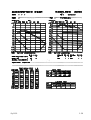
1
CLINICAL AUDIOMETER
SIBELMED AC50
520-600-MU2
* USER´S MANUAL *
SIBELMED-AC50 CLINICAL AUDIOMETER
*USER’S MANUAL*
EO1
CONTENTS
1.INSTRUCTIONS FOR USE AND INSTALLATION
1.1.INTRODUCTION
1.2.PREVIOUS OBSERVATIONS
1.3.DISTRIBUTION OF CONTROLS, INDICATORS AND CONNECTIONS
1.3.1. FRONT AND SIDE PANEL
1.3.2. REAR PANEL
1.4.INSTALLING AND TURNING ON THE AUDIOMETER
1.4.1. INSTALLING TH AUDIOMETER
1.4.2. TURNING THE AUDIOMETER ON
1.4.3. DESCRIPTION OF DISPLAYS
1.4.4. PROGRAMMING THE AUDIOMETER
1.5. AUDIOMETRIC TESTS
1.5.1. TONAL AUDIOMETRY
1.5.2. FOWLER TEST
1.5.3. SISI
1.5.4. TONE DECAY TEST
1.5.5. LÜSCHER TEST
1.5.6. SPEECH AUDIOMETRY
1.5.7. FREE AUDIOMETRY
1.6.PROCEDURE TO BE CARRIED OUT FOR TONAL AUDIOMETERY
1.6.1. DETERMINING AUDITIVE THRESHOLD BY AIR CONDUCTION WITHOUT
MASKING
1.6.2. DETERMINING AUDITIVE THRESHOLD BY AIR CONDUCTION WITH MASKING
1.6.3. DETERMINING AUDITIVE THRESHOLD BY BONE CONDUCTION WITHOUT
MASKING
1.6.4. DETERMINING AUDITIVE THRESHOLD BY BONE CONDUCTION WITH
MASKING
1.6.5. “SCREENING” AUDIOMETRY
1.7. PROCEDURE TO BE CARRIED OUT FOR FOWLER TEST
1.8. PROCEDURE TO BE CARRIED OUT FOR SISI TEST
1.9. PROCEDURE TO BE CARRIED OUT FOR TONE DECAY TEST
1.10. PROCEDURE TO BE CARRIED OUT FOR TONE DECAY TEST
1.11. PROCEDURE TO BE CARRIED OUT FOR SPEECH AUDIOMETRY TEST
1.12. PROCEDURE TO BE CARRIED OUT FOR FREE AUDIOMETRY
1.13. PRINTOUT AND MEMORISATION OF AUDIOMETRY TESTS
1.13.1. PRINTOUT OF AUDIOMETRIC DATA
1.13.2. MEMORISATION OF AUDIOMETER RESULTS IN THE INTERNAL DATABASE
1.13.3. EXTERNAL DATABASE AND RS-232 CHANNEL
1.14. AUTOMATIC CALCULATION OF AUDITIVE LOSS
1.14.1. PERCENTAGE OF AUDITIVE LOSS
1.14.2. PERCENTAGE OF BILATERAL AUDITIVE LOSS
1.14.3. MEAN AUDITIVE LOSS IN dB
1.14.4. CATEGORIZING OF AUDITIVE LOSS
2.TECHNICAL SPECIFICATIONS
2.1.TYPES OF TEST
2.2.SIGNAL GENERATORS
2.3.CONTROLLING THE SIGNAL LEVELS
2.4.OTHER FUNCTIONS
2.5.TRANSDUCERS
2.6.REGULATIONS APPLICABLE
2.7.GENERAL INFORMATION
3.FUNCTIONING PRINCIPALS
3.1.SIGNAL SOURCES
3.1.1. TONE GENERATOR
3.1.2. SPEECH AUDIOMETRY
3.1.3. NARROW BAND NOISE
3.1.4. VOCAL NOISE
3.1.5. SOURCE SELECTOR
3.2. RIGHT-HAND CHANNEL
3.2.1. MODULATOR
3.2.2. ATTENUATOR
3.2.3. INTERRUPTING THE SIGNAL - SILENCER
3.2.4. CHANNEL SELECTOR
3.2.5. AMPLIFIER
3.3. LEFT-HAND CHANNEL
3.4. MICROPROCESSOR
3.4.1. PHYSICAL DESCRIPTION
3.4.2. PROGRAM
3.4.3. RAM MEMORY
3.4.4. CPU
3.4.5. PERIPHERALS
3.5.INTERCOM
3.6.FREE FIELD
4. AUDIOMETRY TECHNIQUE
5. GENERAL MAINTENANCE, PREVENTIVE MAINTENANCE, CORRECTIVE
MAINTENANCE
5.1.GENERAL MAINTENANCE
5.1.1. CLEANING THE AUDIOMETER
5.1.2. CLEANING THE ACCESSORIES
5.2. PREVENTIVE MAINTENANCE
5.2.1. ROUTINE CHECKING AND SUBJECTIVE TESTS
5.2.2. OBJECTIVE CHECKING
5.3.CORRECTIVE MAINTENANCE
6.MODIFICATIONS
SIBEL S.A.
Dos de Maig, 290
08025 - BARCELONA
1.INSTRUCTIONS FOR USE AND INSTALLATION
1.1.INTRODUCTION
The SIBELMED AC50 clinical audiometer is a compact apparatus with two channels based principally on a
tone generator, a noise generator, a set of air-conduction earphones, a bone vibrator and two alphanumeric
liquid cristal display screens. The whole system is controlled by a micro-processor which enables audiometric
examinations to be carried out reliably, quickly and simply in order to determine hearing thresholds and
perform “screening” tests as well as supraliminar tonal tests.
The SIBELMED AC50 clinical audiometer was developed entirely in Spain in keeping with the latest
technology, after more than 15 years of experience in the field designing and manufacturing similar apparatus.
The apparatus’ functional design combined with the minimising of electromechanical components allow for
the production of apparatus which provide a lasting service carrying out audiometric tests.
The SIBELMED AC50 clinical audiometer was designed in collaboration with prestigious experts in the field
and meets the standard criteria of the National Institutions U.N.E. as well as the International Institutions I.E.C,
I.S.O, etc.
1.2.PREVIOUS OBSERVATIONS
This audiometer is manufactured using professional components in perfect condition under strict quality
control tests. However, accidents may occur during transport or storage, so it is advisable to check the
apparatus and complementary accessories over before installation.
WARNING
IF ANY DAMAGE IN THE PACKAGING IS FOUND, CONTACT THE TRANSPORT
AGENCY AND DISTRIBUTOR IMMEDIATELY BEFORE PROCEEDING TO INSTALL THE
APPARATUS. DO NOT DISPOSE OF PACKING, BAGS ETC. UNTIL THE CORRECT
FUNCTIONING OF THE APPARATUS HAS BEEN THOROUGHLY CHECKED.
The SIBELMED AC50 series of audiometers is presented in three different models:
SIBELMED AC50-B
SIBELMED AC50-C
SIBELMED AC50-D
The following table shows the basic characteristics comprising each standard model (X) plus the parts which
can be included optionally (O). At any stage, if desired, a given model may be converted into a superior one
by adding the corresponding parts.To do this it will be necessary to contact SIBEL S.A.’s commercial
department or distributor.
1- 1
MODELS
TWO CHANNELS
AIR CONDUCTION
BONE CONDUCTION
FREE FIELD
SPEECH AUDIOMETRY
NARROW BAND NOISE
SPEECH NOISE
PULSE TONE
FREQUENCY MODULATION
AMPLITUDE MODULATION
ABLB
SISI
AUDITIVE LOSS CALCULATION
INTERCOM
AUTOTESTING
PATIENT’S RESPONSE BUTTON
ATTACHMENT
OUTPUT TO PRINTER
RS232-C CHANNEL
INTERNAL MEMORY
PC DATABASE
AUDIOCUPS AC
PRINTER
CARRYING BAG
AC50-B AC50-C AC50-D
X
X
X
X
X
X
O
X
X
O
O
O
O
X
X
X
X
X
X
X
X
X
X
X
X
X
X
X
X
X
O
X
X
X
X
O
O
X
X
X
X
X
X
X
O
O
O
O
X
X
X
X
O
O
O
O
X
X
X
X
O
O
O
O
The SIBELMED AC50 audiometer consists of the following items and accessories:
CODE
520-600-000
520-540-001
520-540-002
520-550-001
520-641-010
305-350-020
520-600-MUI
175-600-020
175-600-060
520-670-004
520-680-003
520-680-002
QUANTITY
1
1
1
1
50
1
1
1
1
1
1
1
DESCRIPTION
SIBELMED AC50 AUDIOMETER (Depending on model)
PATIENT’S RESPONSE BUTTON ATTACHMENT
SET OF AIR-CONDUCTION EARPHONES
BONE CONDUCTION VIBRATOR (Depending on model)
AC50 AUDIOMETRY GRAPH
MAINS CONNECTION CABLE 2m
SIBELMED AC50 USER’S MANUAL
RED BALL-POINT PEN
BLUE BALL-POINT PEN
SPEECH AUDIOMETRY MICROPHONE (Depending on model)
PATIENT’S INTERCOM MICROPHONE (Depending on model)
SET OF EARPHONES FOR MONITOR (Depending on model)
The optional parts will be supplied along with the accessories necessary to enable each corresponding test.
These code numbers may be used in order to order replacements of accessories.
1- 2
NOTICE
In compliance with various regulations, it is recommended that the electromedical apparatus
be checked periodically in order to ensure that it is functioning correctly and for the safety
of the patient, user and working environment.
Besides the necessary routine checks on the SIBELMED AC50 audiometer, it is advisable
gauge the transducers and to service the safety systems, adjustments, functions etc. at least
every twelve months (ISO 8253-1). This must also be done whenever it is suspected that the
machine is functioning incorrectly.
These services must be carried out in line with the manufacturer’s (SIBEL S.A.) Checking and
Adjustment Procedures, by the manufacturer itself or by technical personnel qualified and
authorised by SIBEL S.A.
RESPONSIBILITY OF MANUFACTURER
SIBEL S.A. will hold itself responsible for the safety, reliability and correct functioning of this apparatus only
when:
The premises in which the apparatus is installed complies with the requirements regarding electrical
installations UNE (IEC), including earthing as well as the other applicable regulations.
Reparations, servicing and modifications both inside and outside the guarantee period are carried out by SIBEL
S.A.’s technical personnel.
The machine is used by qualified personnel and according to the recommendations in this User’s Manual.
1- 3
1.3. DISTRIBUTION OF CONTROLS, INDICATORS AND CONNECTIONS
1.3.1. FRONT AND SIDE PANEL Fig. 1.3.1.
The audiometer is controlled by means of a touch-sensitive keyboard situated on the front panel. When in
use this keyboard system produces no sound or interference which could distort the signal applied to the
patient.
Many of the keys have two functions, all of which would be tedious to describe in this section. In order to
provide a clearer understanding, the main function of each key will be described below and the other functions
will be described as necessary along with each test.
All controls, indicators and connections which may be incorporated in the front and side control panel of
the SIBELMED AC50 audiometer will be described below. Some of them may not exist or be activated in
certain models (See section 1.2.- PREVIOUS OBSERVATIONS).
1:
On-off switch “0” OFF (Light off), “I” ON (Light on)
2:
Information panel
3:
Display corresponding to left channel (BLUE)
4:
Display corresponding to right channel (RED)
5:
Signal input level indicator for speech audiometry
6:
Control keys corresponding to the left channel:
- “F1” For selection of signal application route according to information panel 2
- “F2” For selection of mode or form of presentation of the signal according to information panel 2
- “F3” For selection of source or type of signal according to information panel 2
- “ “ Attenuator or key used to increase level of the signal applied to patient in 5 dB (decibel) steps.
- “ “ Attenuator or key used to diminish the level of signal applied to patient in 5 dB steps.
- “SIGNAL” Silencer, or when activated key which sends or blocks the signal transmitted to patient, depending
on mode of “direct/inverted” key 9.
7: “ “
Key used to increase signal frequency of pure tones applied to patient (125, 250, 500, 750, 1000, 1500, 2000,
3000, 4000, 6000, 8000 Hz)
8: “ “
Key used to diminish the signal frequency of pure tones applied to patient (125, 250, 500, 750, 1000, 1500,
2000, 3000, 4000, 6000, 8000 Hz)
1- 4
9: “INVER”
Key which enables the inversion of “direct/inverted” functions of the “SIGNAL” keys of each channel as well
as other functions to be described further on.
10:
Control keys corresponding to the right channel:
- “F1” Selection of signal application route according to information panel 2
- “F2” Selection of mode or form of presentation of the signal according to information panel 2
- “F3” Selection of source or type of signal according to information panel 2
- “ “ Attenuator or key used to increase level of the signal applied to patient in 5 dB (decibel) steps.
- “ “ Attenuator or key used to diminish the level of signal applied to patient in 5 dB steps.
- “SIGNAL” Silencer or, when activated, key which sends or blocks the signal transmitted to patient, depending
on mode of “direct/inverted” key 9.
11:
Key used to introduce patient’s reference in a test to be printed out, memorized in the machine’s internal
database or transferred to a PC database.
12:
OPTIONS MENU key used to select test, see patient’s reference or to erase incorrectly typed characters.
13:
Key used to access machine’s internal database, capable of storing up to fifty audiometer tests.
14: “SISI”
Key used to manually create increases in SISI tests.
15: “RESET”
Key used to erase information to be described further on.
16:
Key used to activate intercom in order to establish dialogue with the patient.
17: “I”
By means of this key, hearing thresholds which have been memorised through the INTRO 19 key can be
visualised.
18:
Key used to enable the printing of audiometric file cards when the thresholds have been memorised previously
by means of the INTRO 19 key.
19:
INPUT key used to enable storing of test thresholds as well as to consent selected or input information.
1- 5
Fig. 1.3.1.
1.3.2. REAR PANEL AND ACCESSORIES Fig. 1.3.2.
20:
Main fuse sockets holding slow 5x20 0.25A fuses.
21:
Connection socket for additional protection.
1- 6
22:
Mains and earth connection socket.
23:
Characteristics plaque.
24:
Socket for earphones of technician carrying out the test (intercom).
25:
Patient’s microphone connection socket (intercom).
26:
Signal level adjustment control for intercom.
27:
Signal level adjustment control for speech audiometery input.
28:
Signal level adjustment control for auxilliary input for speech audiometry tests.
29:
Input socket for auxilliary signal in speech audiometery tests.
30:
Microphone connection socket for speech audiometery tests or for the intercom (operator’s).
31:
Connection socket for patient’s response button attachment.
32:
Connection socket for left Air Conduction (AC) earphones.
33:
Connection socket for right Air Conduction (AC) earphones.
34:
Connection socket for Bone Conduction (BC) vibrator.
35:
Connection socket for amplifier corresponding to Free Field (FF)(Speakers cannot be connected directly as
a potency amplifier with graded levels is needed).
36:
External printer connection socket.
37:
RS-232C socket for connection of audiometer to a PC or other computer system.
1- 7
38:
Earphones for signal application by means of Air Conduction.
39:
Vibrator for signal application by means of Bone Conduction.
40:
Patient’s response button attachment.
Fig. 1.3.2.
1- 8
1.4. INSTALLING AND TURNING ON THE AUDIOMETER
1.4.1. INSTALLING THE AUDIOMETER
In accordance with the type of protection against electric shocks established in the regulation UNE 20.613
(IEC 601.1), the SIBELMED AC50 audiometer is listed as a CLASS 1 machine.
The SIBELMED AC50 audiometer requires a 220V and 50/60 Hz ±10% mains terminal (XXXX) with its
corresponding earth terminal in compliance with the UNE (IEC) regulations currently in effect. The required
power must be below 40 VA.
The required atmospheric conditions are:
- Storage temperature from 0 to 60°C.
- Atmospheric temperature between 10 and 40°C.
- Relative humidity below 90% (without condensation).
The mains cable which is included incorporates an earth (yellowgreen) as it is required that the audiometer like any other CLASS 1 electromedical apparatus be connected
to earth.
It is recommended that the audiometer be installed together with a sound-proof booth for
audiometry tests. Where this is not possible the machine must be installed in a room in which
the atmospheric noise-level is low enough not to distort test results. Failing this, NOISE
SUPPRESSORS can be adopted for the earphones (OPTIONAL).
Caution must be taken not to place the apparatus anywhere near water or other liquids which may splash
it, or to place other objects on the apparatus which could impede the circulation of air in the machine while
it is functioning.
The sequence of operations needed to prepare the SIBELMED AC50 to carry out audiometric tests is as
follows:
1. Main switch 1 in position “0” OFF (light off).
2. Connect the mains connection cable to socket 22 and to the mains 220V 50/60 Hz ±10% (XXXX).
3. Connect the accessories to the corresponding sockets.
When all the steps described have been gone through the apparatus will be ready to operate.
1.4.2. TURNING THE AUDIOMETER ON
In order to turn the audiometer on, press switch 1 to position “I” ON. The switch will then light up.
For some seconds the apparatus will carry out an auto-check soas to verify whether all the accessories are
connected and that the original gauging is correct. If the result is negative the machine will indicate this. This
gauging check presupposes that both the air conduction and bone conduction transducers are working
correctly and have not deteriorated. In order to prevent this and also when improper functioning is suspected,
1- 9
it is necessary to run an MINIMUM PERIOD ANNUAL GAUGING, with an artificial ear and mastoids. Once
the auto-check is completed the audiometer automatically sets all the controls and indicators as programmed
(See section 1.4.4. PROGRAMMING THE AUDIOMETER).
1.4.3. DESCRIPTION OF DISPLAYS
Before beginning the explanation of the various audiometric tests, it is necessary to describe the characters
which appear in displays 3 (left channel) and 4 (right channel). These displays show the settings of the apparatus
at all times.
Information panel 2 can be used to see the main characters which appear on the displays and their meaning
within different audiometric tests.
Each display is made up of 16 alphanumeric characters. The figure below shows the appearance of the displays,
the two being the same except for a few functions which will be described further on.
The characters which can be shown on each digit of the display when the apparatus is carrying out an
audiometric test are shown below. There are other modes, mainly for programming or information, which
will be commented upon as necessary as they come up.
RIGHT CHANNEL DISPLAY
The characters are as follows:
ABC Corresponds to the signal level applied to the patient in “dB”
D Free
E FIndicates when lit that A signal is being applied to the patient. Controlled by means of key 10 “SIGNAL”
G
Corresponds to the application channel and is controlled by means of the “F1” key as follows:
. A Air Conduction (AC)
. B Bone Conduction (BC)
. F Free Field (FF)
. -- Deactivated
H
Corresponds to the type of signal emmited and is controlled by means of the “F2” key as follows:
. C Continuos signal
. P Pulsating signal
. ”P” (Intermittent) Pulsating signalalternating between left and right channels.
. M Modulated volume signal (MV)
. ”M” (Intermittent) Modulated volume signal alternating between left and right channels.
. S SISI mode signal
. -- Deactivated
I Free
1- 10
JKLM Corresponds to the source or type of signal used and is controlled by means of the “F3” key as follows:
. XXXX Frequency in Hz of Pure Tone
. NBN Masking with narrow band noise.
. SN Masking with speech noise
. SPE Speech audiometry
. ”XXXX” (Intermittent) Pure tone in Hz with modulated frequency.
N Free
OP Corresponds to the number of “1 dB” increases sent to patient in SISI mode.
LEFT CHANNEL DISPLAY
Display 3 corresponding to the left channel is identical to the right one except regarding the OP characters
which correspond to the number of stimulus detected in the patient and when in SISI mode in the TONE
DECAY test corresponds to seconds during which the patient has heard the signal.
1.4.4. PROGRAMMING THE AUDIOMETER
Any apparatus possessing a high number of functions can be manipulated voluntarily or involuntarily by a third
party, so altering the standard programming of the controls, thereby compromising their convenient use.
In order to make up for this shortcoming, the SIBELMED AC50 audiometer is provided with a programming
facility which enables the user to define the initial working program which is then recovered each time the
apparatus is switched on.
This information is kept in an independently powered solid-state internal memory which enables the machine
to be turned off without its loss.
The initial programming must be carried out in the following manner:
1-Set the controls to the operating position desired when the audiometer is switched on.
2-Type key 12 corresponding to the MENU.
3-Select the option “STORE PROGRAM” by pressing key 7upwards or by pressing key 8 downwards.
4-Type key 19 INTRO.
From this moment on the audiometer will automatically go to the programmed setting whenever the
apparatus is switched on.
The only function which cannot be programmed is that corresponding to the silencers of each channel 6 and
10. These will always remain in the “direct” position (the signal will not be applied unless these keys are typed).
1- 11
1.5. AUDIOMETRIC TESTS
The SIBELMED AC50 audiometer permits the execution of many types of audiometric examination in
supraliminar tonal audiometry as well as regular tonal audiometry.
A MENU containing the most used examinations has been established to facilitate use of the apparatus and
if desired, printed reports can be produced automatically. This will not prevent the user from filling in the
reports manually or from caryying out many other tests within the FREE AUDIOMETRY option.
The tests carried out on the audiometer are visualised by means of key 12 for the OPTIONS MENU. Keys
7 and 8 are used to select the option and the INTRO key 19 is used to enter the desired test. The options
are as follows:
1
2
3
4
5
6
7
TONAL AUDIOMETRY
FOWLER TEST
SISI
TONE DECAY TEST
LÜSCHER TEST
SPEECH AUDIOMETRY
FREE AUDIOMETRY
Within the MENU there are other functions which have already been mentioned or which will be mentioned
further on, such as:
-
ERASING OF THE DATABASE
REPORT FORMAT
PROGRAMMING STORAGE
FINISHING
The mechanics needed to carry out some audiometric examinations are explained in this
manual. There are other methods so it must remain subect to the criteria of the specialist
which is the most appropriate method in each case.
Besides these, there are other variations of the tests which are not included. The procedures for carrying
out these tests must be determined by the specialist carrying out the test.
It is recommended that persons who are not very familiar with these techniques should consult the relevant
literature.
A brief description of each of the tests presented in the OPTIONS MENU is given below.
1.5.1. TONAL AUDIOMETRY
Tonal audiometry is the basic test consisting of the determiningof of the levels of auditory threshold by use
of air conduction and bone conduction, with and without NBN masking.
1- 12
Free field audiometry is done as if dealing with tonal audiometry by air conduction.
This test can be carried out using models AC50-B, AC50-C and AC50-D.
1.5.2. FOWLER TEST
This test is done in order to determine whether there is recruitment when one auditive threshold is normal
or below 30 dB and the other shows a loss of 25 to 60 dB.
This test is also called ABLB (Alternate Binural Loudness Balance).
This test may be carried out using models AC50-B, AC50-C and AC50-D.
1.5.3. SISI
SISI (Short Increment Sensitivity Index according to Jerger). It consists of 1 dB increases of a pure tone with
an increase time of 50 ms, a duration of 200 ms and a decrement of 50 ms. The stimulus may be applied either
manually or automatically every 5 seconds.
This test can be done with model AC50-D and also with model AC50C if it the option is incorporated.
1.5.4. TONE DECAY TEST
The TONE DECAY TEST according to CARHART consists of applying a pure tone 5 dB above the auditive
threshold to the patient and observing whether it is perceived clearly over a 60 second period. Normally it
will be perceived in this time. If not, the level is increased in 5 dB steps until it can be heard and then until
it is confirmed to be heard over the period of a minute.
This test can be carried out using models AC50-B, AC50-C and AC50-D.
1.5.5. LÜSCHER TEST
This test consists of the application of a tone of modulated amplitude 40 dB over the threshold and
determining the modulation threshold by raising or lowering the level of the tone, the threshold being found
at the level at which the subject can nolonger hear or begin to hear the modulation of the tone.
This test can be done using models AC50-C and AC50-D.
1.5.6. SPEECH AUDIOMETRY
Speech or vocal audiometry basically consists of determining the intelligibility threshold (the patient hears and
understands the word pronounced) by means of a list of words pronounced or recorded material.
1- 13
There are many variations of speech audiometry which are not described in this manual and remain at the
discretion of the user.
The test may be done using model AC50-D and also with model AC50C if the option is incorporated.
1.5.7. FREE AUDIOMETRY
This option included in the audiometers MUST NOT BE CONFUSED WITH FREE FIELD.
By selecting “FREE AUDIOMETRY” the user can carry out any other test using the audiometer, including
those described above as the audiometer permits access to and selection of all functions although some may
be irrelevant.
In the tests described previously, the machine’s software blocks some functions which would not normally
be used for that particular test and variations are therefor impossible. Using the “FREE AUDIOMETRY”
option permits access to any of the functions possible for the apparatus.
These tests can be done using models AC50-B, AC50-C and AC50-D.
1- 14
1.6. PROCEDURE TO BE CARRIED OUT FOR TONAL AUDIOMETRY
Variations in tonal audiometry methods are as follows:
- DETERMINING OF AUDITIVE THRESHOLD BY AIR CONDUCTION WITHOUT MASKING
- DETERMINING OF AUDITIVE THRESHOLD BY BONE CONDUCTION WITHOUT MASKING
- DETERMINING OF AUDITIVE THRESHOLD BY AIR CONDUCTION WITH MASKING
- DETERMINING OF AUDITIVE THRESHOLD BY BONE CONDUCTION WITH MASKING
- “SCREENING” AUDIOMETRY
As described previously, the mechanics needed to carry out certain audiometric examinations are described
in this manual. These methods are not the only ones and therefor must be adapted to the specialist’s criteria
in each case.
Following is a desription of each type of tonal audiometry according to regulation ISO 8253-I.
1.6.1. DETERMINING OF AUDITIVE THRESHOLD BY AIR CONDUCTION WITHOUT
MASKING
The SIBELMED AC50 incorporates the following pure tone frequency levels to be applied by air conduction:
Hz
125 250 500 750 1000 1500 2000 3000 4000 6000 8000
Max. dB HL
80 100 120 120 120 120 120 120 120 110 100
Min. dB HL
-10 -10 -10 -10 -10 -10 -10 -10 -10 -10 -10
(HL = Hearing Level)
A.- GENERAL ASPECTS
- Technicians
Before performing the audiometric tests, technicians must be instructed in the theory and practice of
these tests as it will be necessary to take decisions such as:
- Which ear should be examined first? (Normally that considered to have the best hearing by
the patient)
- Is masking required or not?
- When does the patient’s response correspond to the signal? (The AC50 indicates discrepancies)
- Is there any external noise or patient’s response which could invalidate the test?
- Will the test be continued or reapeated during the interruptions?
- etc.
- Testing Time
It is important to try not to tire the patient as the results may be difficult to obtain if the test exceeds
20 minutes without pausing to rest.
1- 15
- Atmospheric Conditions
It is recommended that the audiometer be installed together with a sound-proof booth inwhich to
perform audiometry tests. Where this is not possible the apparatus must beinstalled in a room in which
the atmospheric noise is sufficiently low so as to not distort test results. Failing this, NOISE
SUPRESSORS for the earphones can be adopted (OPTIONAL).
B.- PREPARATING AND INSTRUCTING THE PATIENT
- Preparing the patient
If the patient has recently been exposed to high noise levels, a temporary increase in auditive thresholds
may be produced. For this reason high noise levels must be avoided before testing or it should be
indicated in the report. In order to avoid errors as a result of physical effort, it is recommended that
the patient arrive at the place of testing at least five minutes before performing the test.
An otoscopic examination will normally be given by a qualified person in order to see whether there
is any obstruction in the external auditive canal which must be removed.
It is absolutely necessary for the patient to be examined to be comfortably seated, calm and alert in
order to be able to pay full attention to the test.
- Instructing the patient
The technician doing the test should explain to the patient what the examination consists of as well
as the following:
.The patient must reply when pressing the patient’s response button.
.The patient must respond when he hears the tone, not when he only thinks he hears it.
.The patient should respond when the tone is heard and stop at the moment when he no longer
hears it.
.The general presentation of the sequence of tones.
.Which ear will be examined first.
- Positioning of the earphones
Glasses and jewelery should be removed if they impede the correct positioning of the air or bone
conduction earphones. As well as this it is advisable to check that hair does not impede the point of
contact between the transducers and the outer ear or mastoids.
The technician will place the air conduction earphones on the patient, checking that they are correctly
adapted, and following the code “RIGHT ear” = RED and “Left ear” = BLUE.
C.- PREPARING THE AUDIOMETER
With the audiometer prepared as indicated in section 1.4. INSTALLING AND TURNING ON THE
AUDIOMETER, the functions can be selected as follows:
1- 16
1. Type key 12 on the OPTIONS MENU. By means of keys 7 and 8 select the option “TONAL
AUDIOMETRY” and enter the test by typing the INTRO key 19.
2. Select each channel with the following indications on the displays.
RIGHT
LEFT
in this example the examination will begin with the right ear.
EF indicates when lit that the signal is being applied to the patient. It is controlled by key 10 “SIGNAL”.
The signal is controlled by means of the “SIGNAL” key. This has two positions: “direct” and “inverted”. The
“direct” position is used to apply the signal to the patient when the key is pressed. The “inverted” position
is used to stop the signal to the patient when the key is pressed. Otherwise, there is a signal.
Move from one option to the other by pressing the “SIGNAL”
key of the corresponding channel and briefly pressing the “INVER” key. When the digits EF appear on the
screen it indicates that there is a signal being applied to the patient or, if not, that there is none.
D.- DETERMINING THRESHOLDS
Once the steps previously described have been followed the auditive thresholds of each ear must be
determined.
NOTICE
IN ORDER TO MEMORIZE THE THRESHOLDS SO AS TO PRODUCE A GRAPH THROUGH
A PRINTER, OR TO MEMORIZE THEM IN THE INTERNAL DATABASE AND/OR TRANSFER
THEM TO A PC DATABASE, SEE SECTION 1.13 PRINTOUT AND MEMORIZING OF
AUDIOMETRIC TESTS.
The test tone is continuous and lasts between one and two seconds. The signal will be applied in “direct” mode
when pressing the “SIGNAL” key. When the patient responds the interval between tones will vary but will
not be shorter than the duration of the tone.
NOTE:
The patient’s response on pressing the response button will be shown flashing on the display
in dB of the signalapplied.
If the patient presses the response button when no signal has been applied the displays briefly
indicate the figures.
1- 17
RIGHT
LEFT
In the first place it will be useful to carry out a practice test in order to familiarise the patient with the process.
Do this in the following manner:
- Apply a 1000 Hz tone by means of keys 7 and 8.
- Apply a level which will be clearly audible (increase-decrease dB keys), for example 40 dB for a normal
subject.
- Reduce the tone in steps of 20 dB until the patient can no longer hear it.
- Increase the level until it is heard again.
- Emit the tone again at the same level.
If the patient’s response is consistent, the check is correct. If not, repeat the process.
The steps to be followed in order to determine auditive thresholds are as follows:
1. The order of application of the tones is: 1000, 1500, 2000, 3000, 4000, 6000, 8000, 750, 500, 250,
and 125 Hz.
Some of these tones can be omitted at the specialist’s discretion.
2. Apply the tone at 10 dB below the threshold detected during the familiarising test. Gradually increase
the level in 5 dB steps until the patient responds.
3. After the response, reduce the level in 10 dB steps until there is no response and then begin to increase
it again. Continue the process until there are three responses at the same level within a maximum of
five ascensions (or two responses within three ascensions, abreviated method).
If less than three responses every five ascensions (or less than two reponses every three ascensions)
are detected, apply a tone 10 dB above the level of the last response and repeat the process.
4. In the graph corresponding to the ear subject to testing, record the auditive threshold corresponding
to the lowest level at which the patient’s responses are more than half of the ascensions.
Note:
If the lowest response levels on a certain frequencydiffer more than 10 dB, the auditive threshold must
be cosidered suspect and the process must be repeated. If there is a difference equal to or over 15
dB between two correlated frequencies, the audiometery results must be considered suspect unless
they represent a sustained incline in the curve. In the case of neurosensorial hypoacusis with a major
loss of high pitched sounds there tends to be more than 15 dB between two correlative frequencies,
1- 18
but the curve maintains this tendency.
5. Repeat steps 2, 3, and 4 for the following frequency.
At the end of the chapter, Figs. 1.13.1. and 1.13.3. show an audiometric file produced by a printer.
1.6.2. DETERMINING AUDITIVE THRESHOLDS BY AIR CONDUCTION WITH MASKING
In order to avoid the test tone being heard by the opposite ear to that which is being examined, it is necessary
to apply a masking noise to that ear.
The SIBELMED AC50 audiometer incorporates a Narrow Band Noise masking system with the following
masking levels to be applied at each frequency using air conduction:
Hz
Max. dB HL
Min. dB HL
125
60
-10
250 500
80 100
-10 -10
750 1000 1500 2000 3000 4000 6000 8000
100 100 100 100 100 100 100 90
-10 -10 -10 -10 -10 -10 -10 -10
(HL = Hearing Level)
Although election of the process and noise to be applied will be largely effected by the technician’s experience,
a method recommended in order to determine auditive thresholds using masking is described below.
1. Apply a test tone to the ear being tested at the same level as the auditive threshold without masking. Select
narrow band noise NBN on the other audiometer channel and apply a masking level at the same level as that
ear’s auditive threshold. Increase the masking level until the test tone can no longer be heard or until it exceeds
the level of the test tone.
2. If the test tone is still audible when the noise level is the same as that of the tone, this is assumed to be the
auditive threshold. If the test tone remains masked, it isincreased until it can be heard again.
3. Increase the noise level by 5 dB. If the test tone is inaudible, increase its level until it is audible again. Repeat
the process until the test tone remains audible even when the masking noise level has been increased by more
than 10 dB. This masking level (which is the level at which no posterior increase in tone level will be required
for audibility) is the correct level for masking and this process should have obtained the correct auditive
threshold for the frequency being tested. Record the correct masking level.
1.6.3. DETERMINING AUDITIVE THRESHOLDS BY BONE CONDUCTION WITHOUT
MASKING
The SIBELMED AC50 audiometer incorporates the following frequencies and pure tone levels for application
by bone conduction:
Hz
Max. dB HL
Min. dB HL
250
50
-10
500 750 1000 1500 2000 3000 4000
60 70
70 70 70 70 70
-10 -10 -10 -10 -10 -10 -10
(HL = Hearing Level)
1- 19
The test tone is applied to the patient by means of a bone conduction vibrator.
WARNING
THE BONE CONDUCTION VIBRATOR IS A VERY FRAGILE ITEM WHICH COULD BE
DAMAGED BY SLIGHT KNOCKS. IT IS THEREFOR RECOMMENDED THAT IT BE
HANDLED WITH CAUTION.
The examination consists of determining the auditive level when pure tones without masking are applied using
bone conduction. In order to do this the channel is selected as in the example below.
RIGHT
LEFT
Investigating thresholds using bone conduction is much more delicate to do and to interpret than other tests.
For this reason special care must be taken when undergoing these tests.
Correct positioning of the vibrator is essential in determining results using bone conduction. It must be placed
on the mastoids, and the tone applied at some dB above the auditive threshold, and the patient told to move
the vibrator on his mastoids until finding the point at which the tone is heard most loudly. Ensure that the
vibrator is firmly in contact with the mastoids and does not touch his outer ear in order to avoid conduction
through the cartillage.
During threshold examinations using bone conduction without masking, the opposite ear must be completely
free, that is to say without wearing air conduction earphones or any other objects, the occlusive effects of
which could alter the results of the test. Otherwise this should be indicated.
With the exception of the points mentioned above, the determining of auditive thresholds by bone
conduction should be carried out as described in section 1.6.1. DETERMINING AUDITIVE THRESHOLDS
BY AIR CONDUCTION WITHOUT MASKING.
1.6.4. DETERMINING AUDITIVE THRESHOLDS BY BONE CONDUCTION WITH
MASKING
The SIBELMED AC50 audiometer permits masking when determining auditive thresholds by bone
conduction without the need to invert the air conduction earphones through which the masking noise is
applied. The NBN levels are as specified in section 1.6.2. Select the channel to be masked using the channel
used for the bone conduction test.
Place the vibrator on the mastoids corresponding to the ear to be examined and ensure the earphones are
correctly positioned. Care must be taken that the transducer’s bands do not interfere with one another.
1- 20
Select each channel by means of the following display indications:
RIGHT
LEFT
In this example the test will first be carried out on the right ear.
Although election of the process and noise to be applied will be largely effected by the technician’s personal
experience, a method recommended in order to determine auditive thresholds by bone conduction using
masking is described below.
1. Apply a test tone to the ear being tested at the same level as that of the auditive threshold without masking.
Select narrow band noise NBN on the other audiometer channel and apply a masking level the same as that
ear’s auditive threshold. Increase the masking level until the test tone can no longer be heard or until it exceeds
the level of the test tone by 40 dB.
2. If the test tone is still audible when the noise level is 40 dB above the test tone, this is assumed to be the
auditive threshold. If the test tone remains masked, it is increased until it is heard once again.
3. Increase the noise level by 5 dB. If the test tone is inaudible, increase its level until it is audible again.Repeat
the process until the test tone remains audible even when the masking noise level has been increased by more
than 10 dB. This masking level (which is the level at which no posterior increase in tone level will be required
for audibility) is the correct level for masking and this process should have obtained the correct auditive
threshold for frequency tested. Record the correct masking level.
1.6.5. “SCREENING AUDIOMETRY”
This type of test is used in cases where the aim is not to find the subject’s auditive threshold, but rather to
determine whether or not he can hear certain levels. This method is simple and easy to perform.
“Screening” audiometry is a test based on determining whether a patient has as auditive threshold the same,
better or worse than the established “screening” level. These “screening” levels are at the specialist’s
discretion.
“Screening” audiometry can be completed by determining the auditive threshold of frequencies for which
the patient has failed the “screening” test. In these cases the procedure will be as described in section 1.6.1.
to determine the threshold.
1- 21
Regarding general aspects, the preparation and instruction of the patient, see section 1.6.1.(A and B).
In order to carry out the test, see the instructions below:
1. Select each channel as in the following displays.
RIGHT
LEFT
In this example the test is begun on the right ear.
2. Select the frequency and the “screening” level. The order in which to apply the frequency of pure tones
is as follows: 1000, 2000, 4000, 6000, 8000, 500 and 250 Hz. Some of these frequencies may be increased
or decreased using others incorporated in the audiometer at the specialist’s discretion.
3. To begin with a 1000 Hz tone and a 40 dB signal level in order to see that the subject has properly understood
the instructions given. If not, re-instruct him and then repeat the tone. If the subject does not respond, increase
the tone level until there is a response.
4. Adjust the signal level to be applied to the requirements of the “screening” level and apply two tones with
a duration of 1 to 2 seconds and an interval between of 3 to 5 seconds between each tone. If both tones are
perceived by the subject, he has passed the test for thatfrequency. If only one tone is heard, apply a new tone.
If this third tone is heard, the subject has passed the test for that frequency. If the third tone or the first two
tones are not heard by the subject, he has failed the screening test.
5. Select another frequency and repeat number 4.
6. Once the right ear has been tested, repeat the process desribed in numbers 4 and 5, blocking the signal
in the right channel and activating that of the left channel as seen below:
RIGHT
LEFT
(The dB level here is given as a guide).
1- 22
1.7. PROCEDURE TO BE CARRIED OUT FOR FOWLER TEST
This test is also called Alternate Binural Loudness Balance or ABLB. It is applied in order to determine whether
there is recruitment when the threshold of one ear is normal or inferior to 30 dB and the other shows a
loss of between 25 and 60 dB.
The requirements regarding general aspects, preparation and instruction of the subject are similar to those
described in section 1.6.1.(A and B).
With the audiometer prepared as desribed in section 1.4. INSTALLING AND TURNING THE AUDIOMETER
ON, proceed as follows:
Type key 12 on the OPTIONS MENU. Using keys 7 and 8 select the “FOWLER TEST” option and enter by
means of the INTRO 19 key.
The procedure to be followed for this test consists of applying a tone of equal frequency to both ears,
alternating between them once a second. The level of intensity for the best ear is progressively increased
starting at the threshold, in 10 to 30 dB steps, while the subjective sonority of the poorer ear is equalised
and its correspondance with the better ear will be shown on a graph.
In this test the signal modes CONTINUOUS and ALTERNATELY PULSATING, the PURE TONE signal
source and the AIR application channel are activated.
1.8. PROCEDURE TO BE CARRIED OUT FOR SISI TEST
The SISI test (Short Increment Sensitivity Index) consists of measuring the ear’s capacity to perceive short
increases in intensity.
The test consists of applying 1 dB continuous tone increases atan increase rate of 50 ms, lasting 200 ms and
descending to 50 ms. The level of increase can be from 2 to 5 dB to train the poatient. The application of
the increase can be automatic or manual and the interval in automatic mode can vary between 1 and 9 seconds,
the normal value being 5 seconds.
The apparatus incorporates a counter for the number of increases applied if they are at 1 dB. The maximum
number is 20 increases.
The requirements regarding general aspects, the preparation and instruction of patients are similar to those
described in section 1.6.1.(A and B). Special care should be taken to explain to the patient the mechanics of
the test in which a constant pure tone will be heard at times, and a jump in the intensity of the tone at others.
At this moment he should respond by pushing the response button.
With the audiometer prepared as described in section 1.4. INSTALLING AND TURNING ON THE
AUDIOMETER, the function may be selected as follows:
1. Press key 12 on the OPTIONS MENU. By means of keys 7 and 8 the option “SISI” is selected and the test
is entered using the INTRO 19 key.
1- 23
2. The displays will appear as in the example below:
RIGHT
LEFT
3. Maintain the INVER key 9 pressed for some seconds. The displays will now show something like this:
RIGHT
LEFT
The position corresponding to dB is the level of increase (1, 2, 3, 4 or 5 dB) and is selected by means of the
dB keys of each channel.
The charaters corresponding to frequency indicate the interval of time between increases when in automatic
mode (1, 2, 3, 4, 5, 6, 7, 8 or 9 seconds) or depending on when the SISI key 14 is pressed if in the MAN position.
Selection is done by means of the Hz keys 7 and 8.
The remaining characters correspond to the description given in section 1.4.3.
Select the dB levels and time intervals to be used. Remember that the stimulus counter only works when the
increases are of 1 dB.
Release the INVER key.
4. Select a working frequency from 500, 1000, 2000 and 4000 Hz.
5. Apply 20 dB above the auditive threshold to thepatient’s right channel.
6. The displays will appear something like the example below:
RIGHT
LEFT
1- 24
7. The increases are applied manually (MAN) by means of the SISI key or automatically, depending on the
selection at point 3. When in automatic it is also possible to apply extra stimulus using the SISI key.
8. The test is begun by pressing the SIGNAL key of the channel corresponding to the ear to be examined
and maintaining it pressed throughout the test, or by maintaining the SIGNAL kay pressed and typing the
INVER key and releasing both so that the audiometer works in “inverted” mode (there will be a continuous
signal unless the SIGNAL key is pressed).
9. The stimulus counter (right channel display) will accumulate 1 dB increases which are applied, and the reply
counter (right display channel) will indicate the responses received. These counters can be reset to zero at
any time using the RESET key 15.
10. Once the selected increases have been sent they are recorded as are the responses received and the
frequency is changed.
The results are normally recorded in percentage form in accordance with
% = number of replies x 100 / number of increases
11. Once the frequencies have been examined in the reight ear, the test is repeated in the left ear.
At the end of the chapter Figs. 1.13.2. and 1.13.3. show an audiometric file produced by a printer.
1.9. PROCEDURE TO BE CARRIED OUT FOR TONE DECAY TEST
The Tone Decay Test according to Carhart consists of applying a tone 5 dB above the threshold to the patient
and observing whether it is perceived clearly over 60 seconds. Normally it is perceived during this time. If
it is not, the level is increased in 5 dB steps until heard and further until the patient confirms that he can hear
it for the entire minute.
Regarding general requirements, the preparation and instruction of the patient are similar to those described
in section 1.6.1. (A and B). Particular care should be taken to ensure that the mechanics of the test, in which
a constant pure tone will beheard, are explained to the patient. The response button must remain pressed
while the patient is listening.
With the audiometer prepared as desribed in section 1.4. INSTALLING AND TURNING ON THE
AUDIOMETER, the function is selected in the following manner:
1. Press key 12 on the OPTIONS MENU. Using keys 7 and 8 the “TONE DECAY TEST” option is selected.
Enter the test by means of the “INTRO” key 19.
2. The displays will appear similar to the ones below:
RIGHT
LEFT
1- 25
The two characters on the right of the left channel will work as a timer counting up to 90 seconds. The timer
starts when the signal is applied.
3. Select a signal level to apply at 5 dB above the auditive threshold level at one of the following frequencies:
250, 500, 1000, 2000 and 4000 Hz.
4. Begin the test by applying a tone by means of the “SIGNAL” key, in either “direct” or “inverted” mode,
for 60 seconds if the response continues. Otherwise, increase the tone level.
At the end of the chapter Figs. 1.13.2. and 1.13.3. show an audiometric file produced by a printer.
1.10. PROCEDURE TO BE CARRIED OUT FOR LÜSCHER TEST
The Lüscher test consists of applying a tone level 40 dB above the auditive threshold, modulating the amplitude
and determining the threshold from the modulation. This will be found, by raising or lowering the level, where
the subject can no longer hear the “wavering” of the tone. The advantage of this test is that it is performed
on one ear only so that the recruitment can be determined where a Fowler test is not useful due to symmetrical
auditive loss.
Regarding general requirements, the preparation and instruction of the patient are similar to those described
in section 1.6.1. (A and B). Particular care should be taken to ensure that the mechanics of the test, in which
a pure tone of moderated amplitude will be heard, are understood by the patient.
With the audiometer prepared as desribed in section 1.4. INSTALLING AND TURNING ON THE
AUDIOMETER, the function is selected in the following manner:
1. Press key 12 on the OPTIONS MENU. Using keys 7 and 8 the “LÚSCHER TEST” option is selected.
Enter the test by meansof the “INTRO” key 19.
2. The displays will appear similar to the ones below:
RIGHT
LEFT
Only the MODULATED, CONTINUOUS and PULSATING modes, the TONE and NBN functions
and the AIR channel will be activated.
3. Press and hold down the INVER key 19 for a few seconds. The displays will look something like the
example below:
RIGHT
LEFT
1- 26
The position corresponding to dB is the modulation amplitude level (0.2, 0.3, 0.4, 0.5, 0.6, 0.8, 1, 2,
3, 4 or 5 dB) and is selected by means of the dB keys of each channel.
The characters corresponding to the frequency indicate the modulation signal frequency which is fixed
at 2.5 Hz.
Release the INVER key.
4. Select the pure tone frequency form the following:
1000, 2000, 4000, 6000 and 8000 Hz.
5. Apply 40 dB above the auditive threshold to the patient through the right-hand channel and begin
the test.
At the end of the chapter Figs. 1.13.2. and 1.13.3. show an audiometric file produced by a printer.
1.11. PROCEDURE TO BE CARRIED OUT FOR SPEECH AUDIOMETRY
Speech or vocal audiometry basically consists of determining the intelligibility threshold (the patient hears and
understands the word pronounced) by means of a list of words pronounced by a live voice or using recorded
material.
Neither the procedure to be followed nor material to be used for this test are standardised and therefor
are left at the specialist’s discretion.
In this section only a basic description of how to use the apparatus in this mode will be given.
In the speech audiometry test only the CONTINUOUS and ALTERNATELY PULSATING modes, the
SPEECH and VOCAL NOISE VN functions and the AIR and FREE FIELD application channels are active.
Regarding general requirements, the preparation and instruction of the patient are similar to those described
in section 1.6.1. (A and B). Particular care should be taken to ensure that the mechanics of the test, in which
words will be heard and must be repeated, are understood by the patient.
With the audiometer prepared as desribed in section 1.4. INSTALLING AND TURNING ON THE
AUDIOMETER, the function is selected in the following manner:
1. Press key 12 on the OPTIONS MENU. Using keys 7 and 8 the “SPEECH AUDIOMETRY” option
is selected. Enter the test by means of the “INTRO” key 19.
2. The displays will appear similar to the ones below:
RIGHT
LEFT
3. Connect the technician’s microphone to socket 30 if the test will be carried out using a live voice,
1- 27
or a tape recorder to socket 29 if recorded material is to be used.
4. If the audiometer is installed in a sound proof booth, connect the patient’s microphone and the
technician’s earphones to be used for the test to sockets 25 and 24.
5. In this test it is convenient to work with the “SIGNAL” levels in “inverted” mode (the signal is applied
without pressing the SIGNAL key) in the channel to be used.
6. Carry out a trial test by adjusting the level of the signal to be applied to the microphone by means
of the regulating control 27 so that when the technician emits the words, with the microphone at a
determined distance, the level indicator 5 lights up the whole green area.
The space between the red and green areas on the level indicator is equivalent to 0 dB, that is to say
there is no increase or loss in the level of the signal applied to the patient. It must be taken into account
that the level of the siganl applied to the patient depends on the level in dB selected for each channel.
If the speech audiometry signal level indicator 5 is completely lit up, this represents a 3 dB increase in
the signal applied. However, if only the first segment is lit up, this represents a 20 dB decrease in the
signal applied.
7. If the apparatus has an intercom, the hearing level of the voice emmited by the patient is adjusted
through the technicians earphones. The intercom functions whenever SPEECH is in operation.
8. The apparatus will now be ready to begin the Speech Audiometry test.
At the end of the chapter Figs. 1.13.2. and 1.13.3. show an audiometric file produced by a printer.
1.12. PROCEDURE TO BE CARRIED OUT FOR FREE AUDIOMETRY
As mentioned previously, many audiometric tests have different variations in procedure, the description of
which would be extensive besides incurring errors or omissions. For this reason the SIBELMED AC50
audiometer incorporates certain options to simplify the performing of the tests.
However, for specialists for whom the options described are limiting, there is an alternative option in which
any test desired may be carried out without the limitation of the software, whilst remaining within the
audiometer’s characteristics.
This option included in the audiometer MUST NOT BE CONFUSED WITH FREE FIELD. By selecting “FREE
AUDIOMETRY” the user can carry out any other test, including those described previously, as the
audiometer allows access to the selection of all the functions even though some of these may seem irrelevant.
Note:
The calibration of FREE FIELD is done from a distance of 1 meter from the speaker to the
central axis where the patient is sitting, his ear and the center of the speaker being on the same
horizontal plane.
1- 28
1.13. PRINTOUT AND MEMORIZATION OF AUDIOMETRY TESTS
The SIBELMED AC50 audiometer has the capacity to print and/or memorize some of the possible
audiometric tests within the apparatus itself or in an external database.
In order to understand more clearly, Fig. 1.13.1. shows a block diagram in which the flux followed by the
audiometric data generated by the apparatus is shown.
DETECTION OF THRESHOLDSTEMPORARY MEMORY
PRINTER
INTERNAL DATABASE
PC DATABASE
THRESHOLD
DETECTION
TRANSITORY
MEMORY
PRINT
INTERNAL
DATA BASE
PC
DATA BASE
Fig. 1.13.1.
As shown in the diagram, the audiometer has the capacity to store the auditive thresholds detected in a
temporary memory in order to perform the following tasks:
- Audiometric data printout through an external printer.
- Storing of audiometric data in an INTERNAL DATABASE.
- Transferring of audiometric data to an EXTERNAL DATA BASE IN A PC.
1- 29
1.13.1. PRINTOUT OF AUDIOMETRIC DATA
A.- Type of printer
The printer to be connected to socket 36 must be an IBM Graphicstype printer. An HP Desk-jet 520 ink-jet printer or compatible alternative for adaptability to the apparatus
and low noise level is recommended.
The presentation format can be selected by means of the OPTIONS MENU key 12. Two format types are
available for selection by entering REPORT FORMAT:
- 11 inch (279.4 mm) format
- DIN A4 (279 mm) format
B.- Tests which can be printed
The information which can be printed includes that of all the tests defined in section 1.5. AUDIOMETRIC
TESTS, with the exception of FREE AUDIOMETRY.
- TONAL AUDIOMETRY
- FOWLER TEST
- SISI
- TONE DECAY TEST
- LÜSCHER TEST
- SPEECH AUDIOMETRY
C.- Procedure to be followed for tests to be printed
The procedure to be followed whilst performing tests which are to be printed are as follows:
1. Press key 11 to assign a reference number of a maximum of ten charaters to the patient to be subjected
to the test. This reference is introduced by means of the keys for digits 0 to 9 and finalised by means
of the INTRO 19 key.
2. Select the option which corresponds to the teest to be carried out by means of the Menu key 12.
The test being carried out and the patient’s reference number can be seen at all times. If no reference
number has been assigned, the information cannot be recorded.
3. Perform the test as described in section 1.6.- PROCEDURE TO BE CARRIED OUT FOR TONAL
AUDIOMETRY and the following tests. The following considerations must be taken into account for
each corresponding test:
TONAL AUDIOMETRY
The only variation is that, once the threshold has been determined, with the channel level
corresponding to that threshold, the INTRO key 19 is pressed for and for a few seconds the
right channel display will show the message “THRESHOLD STORED”. If masking is being applied
to the opposite ear, the level must be correct before pressing INTRO.
NOTICE
The memorization is done independently for each threshold and masking level if
1- 30
one is used. The apparatus will only store the last threshold detected before
pressing INTRO.
FOWLER TEST
For this test, the thresholds corresponding to each channel for which the patient indicates that
he hears the same level in both ears are stored. A signal must have been applied to both ears
simultaneouously.
The dB level indicators are situated correctly and INTRO is pressed.
SISI
For this test, once the twenty 1 dB signal increases have been applied and the patient has given
the corresponding responses, if he has heard, with the data detected in the increase and response
counters, INTRO is pressed.
TONE DECAY TEST
In the tone Decay test the patient gives his responses by means of the response button while he
hears the signal. When he no longer hears it, he releases the button. At that moment the
technician types the INTRO key 19 in order to record the hearing time.
LÜSCHER TEST
In this case the procedure for storing thresholds is the same as that used for Tonal Audiometry.
SPEECH AUDIOMETRY
For speech audiometry, the number of words transmitted to and received from the patient are
fixed at a determined level. With the level selector correctly set, INTRO is pressed and the
audiometer will request the number of words applied and correct responses. This information
is introduced and INTRO is pressed. Other levels or the other ear may then be examined.
FREE AUDIOMETRY
The tests completed in this mode cannot be printed through use of this option.
4. When the auditive thresholds are stored in the temporary memory they can be visualised to check
on doubts or errors by holding down key 17 and moving through the recorded auditive thresholds
by means of the frequency keys 7 and 8. The figures on the right of the displays show the number
corresponding to the type of test being carried out as in the Options Menu (eg. 1 for TONAL
AUDIOMETRY, 2 for FOWLER TEST, etc.). The rest of the information depends on the type of test
selected, as follows:
1.- Tonal AudiometryThreshold and frequency
2.- Fowler TestThreshold and frequency
3.- SISIPercentage and frequency
4.- Tone Decay TestSignal hearing times are presented, the first position corresponding to 250
1- 31
Hz, the second to 500 Hz, the third to 1000 Hz and the fourth to 2000 Hz.
5.- Lüscher TestModulation threshold and frequency.
6.- Speech AudiometryThreshold and percentage of correct replies.
5. If a threshold has been introduced incorrectly, it is repeated on the corresponding channel and
frequency.
6. If it is wished to carry out more than one type of test on the same patient it is not neccessary to print
each one separately as they can be printed together at the end.
7. Finalise the test, type key 18 and the report will be printed automatically.
The report is divided into three areas; the first being composed of tonal audioverbal, the second of the Tone
Decay Test, SISI test and Lüscher test and the fourth of the Fowler and Speech Audiometry test. When a
test is carried out in a certain area, that whole area must be printed out. Otherwise a printout is not possible.
At the end of the chapter Figs. 1.13.2. and 1.13.3. show an audiometric file produced by a printer.
1.13.2. MEMORISATION OF AUDIOMETER RESULTS IN THE INTERNAL DATABASE
The SIBELMED AC50 audiometer incorporates a RAM memory with a capacity for the results of 50 TONAL
AUDIOMETRY tests (othertypes cannot be memorised).
This stored information may be used for:
- Transferred afterwards to a PC database or put through an RS-232C channel.
- Printed out through an external printer.
A.- MEMORIZING A TEST
The process to be followed is the same as that described previously for printing test results in TONAL
AUDIOMETRY, but instead of key 18, key 13 must be pressed.
B.- CONSULTING THE REFERENCES STORED
In order to visualise the test numbers and corresponding references which have been memorised it is
necessary to exit the test being carried out (the data for this test being will be lost if it has not been stored
beforehand). When outside test mode, before assigning a reference by means of key 11 or by pressing key
11 and responding “YES” to the “New Patient” option without introducing any reference, type INTRO.
When in the position described, press key 13 and the screens will show something like the following example:
RIGHT
LEFT
By holding down key 13, the references memorised may be visualised by means of keys 7 and 8.
1- 32
C.- TRANSFERRING THE INFORMATION TO A PC DATABASE
In order to transfer the tests stored in the Internal Database to a PC it is necessary to possess the PC
DATABASE option developed by SIBEL S.A, otherwise the user must effect the application needed. In the
first case, the process to be followed for the transference is described in the User’s Manual of that option.
D.- PRINTING ONE OF THE MEMORISED TESTS
The tests memorised can be printed one by one. To do this keys 13 and 18 must be typed in that order, and
held down until printing begins.
E.- ERASING THE INTERNAL DATABASE
The option “ERASE DATABASE” can be found in the OPTIONS MENU, key 12. If the INTRO key is typed
when in this position, the user will be asked whether he wants to erase the memorised information. If the
reply is affirmative, all the information in the Internal Database is erased.
1.13.3. EXTERNAL DATABASE AND RS-232C CHANNEL
The SIBELMED AC50 audiometer incorporates a type RS-232C-type communication channel which can be
connected through socket 37.
This channel permits information stored in the internal database to be transferred to a computer, as well
as communication in real time with an EXTERNAL DATABASE.
If the user wishes to develop any particular application to be used through this channel, SIBEL S.A. cana provide
the necessary communication protocol between the audiometer and the PC.
SIBEL S.A. can provide you with sophisticated software to enable the storage and management through a PC
of all information provided by the SIBELMED AC50. Moreover, this software permits the visualisation on
the computer screen, in real time, of the graphs corresponding to audiometric tests being undergone.
See the relevant User’s Manual for details of this option.
1.14. AUTOMATIC CALCULATION OF AUDITIVE LOSS
The SIBELMED AC50 audiometer automatically calculates the following parameters when the report is
produced through a printer:
- Percentage of auditive loss
- Percentage of bilateral auditive loss (GLOBAL)
- Average dB of auditive loss
- Catgorisation of auditive loss (Normal, Slight, Moderate, Serious)
1- 33
1.14.1. PERCENTAGE OF AUDITIVE LOSS
The percentage of auditive loss is determined from a tonal audiogram and according to the Council of Physical
Therapy’s 2nd formula.
A percentage of auditive loss is applied to each ear at the following frequencies: 500, 1000, 2000 and 4000
Hz, depending on the importance of the loss, 15% representing 500 to 4000 Hz, 30% for 1000 Hz and 40%
for 2000 Hz. A 0% loss is considered to be a normal loss and a 100% loss is considered to be cofosis. The
percentage of auditive loss for each frequency and intensity level can be found by means of a table drawn for
the organ in question.
The four values are added together, one per frequency for each ear in order to obtain the total percentage
for each ear.
Example
Right ear 500 1000 2000 4000
Loss in dB 15 10 5
10
%
0.5 0.3 0
0.1
Left ear
500 1000 2000 4000
Loss in dB 35 30 40 50
%
3.6 5.4 12.9 8.0
Right total loss
0.9
Left total loss
29.9
1.14.2. PERCENTAGE OF BILATERAL AUDITIVE LOSS: GLOBAL
If the user desires to know the global percentage of bilateral auditive loss, the average is calculated by
multiplying the percentage of the best ear by seven, adding this to the percentage of the poorer ear and dividing
the total by eight. By doing this, the best ear is given priority, which is important regarding inability in
communication.
(% loss in best ear x 7) + (% loss poorer ear)
--------------------------------------------------------------- = % bilateral loss
8
from the previous example
(0.9 x 7) + 29.9
-------------------------- = 4.5% bilateral auditive loss
8
1- 34
1.14.3. AVERAGE AUDITIVE LOSS IN dB
The number of dB loss in the frequencies 500, 1000, 2000 and 4000 are added together and then divided
by four. Following from the previous example:
- Right ear: (15+10+5+10)/4 = 10 dB average auditive loss
- Left ear: (35+30+40+50)/4 = 38 dB average auditive loss
1.14.4. CATEGORIZATION OF AUDITIVE LOSS
The categorization regarding the auditive loss of each ear is as follows:
- NORMAL
- SLIGHT HEARING IMPAIRED
- MODERATE HIPOACUSIS
- SERIOUS HIPOACUSIS
0 to 10% of auditive loss
11 to 30%
31 to 60%
61 to 100%
1- 35
Fig. 1.13.2.
1- 36
Fig. 1.13.3.
1- 37
2. TECHNICAL SPECIFICATIONS
As described in section 1.-INSTRUCTIONS FOR USE AND INSTALLATION, the SIBELMED AC50 is
supplied in three different models which can be complemented by various options not established as standard.
For this reason the following technical specifications correspond to an apparatus including all possible options.
In each case the programming of the audiometer and parts not included should be taken into account.
2.1. TYPES OF TEST
TONAL AUDIOMETRY
- Air conduction without masking
- Bone conduction without masking
- Air conduction with masking
- Bone conduction with masking
- “Screening” audiometry
FOWLER TEST (ABLB)
SISI
TONE DECAY TEST
LÜSCHER TEST
SPEECH AUDIOMETRY
FREE AUDIOMETRY
- Multiple tests or variations, depending on the apparatus (WARBLE, STENGER, etc.)
- Free field audiometry
2.2. SIGNAL GENERATORS
TWO INDEPENDENT CHANNELS
- Right ear
- Left ear
SIGNAL APPLICATION CHANNELS
- Air conduction
- Bone conduction
- Free field
SIGNAL SOURCES
- Pure tones
Frequency: 125, 250, 500, 750, 1000, 1500, 2000, 3000, 4000, 6000 and 8000 Hz
Precision: 2%
- Narrow Band Noise (NBN) for masking
Band: Depending on IEC 645
Attenuation: 12 dB/octave
- Modulated frequency (MF)
Carrying frequency: Pure tones
Modulation frequency: 5 Hz ±1%
Modulation percentage: ±5%
2-1
- Speech audiometry amplifier
Band: 250 to 4000 Hz
Amplitude: Adjustable
Inputs:
Dynamic microphone
Auxilliary input (50 ms ascending signal, 200 ms signal, 50 ms descending signal and 200 ms silence)
Level gauge: LED bar
SIGNAL PRESENTATION MODES
- Continuous
- Pulsating on all frequencies
Frequency: 2 Hz (50 ms ascending signal, 50 ms descending signal and 200 ms silence)
Precision: 3%
- Alternating pulsation:
The same characteristics as the above but alternating between the right and left channels.
- Modulated amplitude
Frequency: 2.5 Hz ±1%
Amplitude modulation: 0.2, 0.3, 0.4, 0.5, 0.6, 0.8, 1, 2, 3, 4 or 5 dB
Ascending and descending time: 50 ms
Level gauge: LED bar
Precision: 3%
- Alternately modulating
The same characteristics as the above but alternating between the right and left channels.
- SISI
Increase presentation: Manual or automatic
Level of increases: 1, 2, 3, 4 or 5 dB
Presentation in automatic mode: Every 1, 2, 3, 4, 5, 6, 7, 8 or 9 seconds
Duration of increase: 50 ms ascending signal, 200 ms signal and 50 ms descending signal
Precision: 3%
2.3. CONTROLLING THE SIGNAL LEVELS
MAXIMUM SIGNAL LEVELS
.Frequency
.AC dB HL
.BC dB HL
.Free field
.Masking AC dB HL
.Masking BC dB HL
125
80
--60
--
250 500 750 1000 1500 2000 3000 4000 6000 8000
100 120 120 120 120 120 120 120 110 100
50 60 60
70 70
70 70 70
--70 80 80
80 80
80 80 80 80
-80 100 100 100 100 100 100 100 100 90
40 50 50
60 60
60 60 60 60
--
.Masking SN dB SPL100
.Speech audiometry
Air conduction dB HL100
Free field dB HL70 (at 1 meter from the patient)
2-2
MINIMUM SIGNAL LEVELS
-10 dB in all cases
INCREASES IN SIGNAL LEVELS
.5 dB steps ±1 dB
PRECISION OF SIGNAL LEVELS
.Precision: ±3 dB
TONE INTERRUPTION: SILENCERS
.Independent for each channel
.Modes
“direct” (signal when button is pressed)
“inverted” (signal when button not pressed)
.Attenuation: > 80 dB
.Ascension and descension time: 50 ms
2.4. OTHER FUNCTIONS
PERSONALISED PROGRAMMING OF FUNCTIONS
PRESENTATION OF STATE OF FUNCTIONS
.Independent for each channel
.16 character alphanumerical LCD display
INTERCOM
.Between operator and patient
.Signal level controller
MEMORY
.Type: RAM
.Capacity: 50 tests
OUTPUTS
.Centronics Parallel-type printer
.RS 232C series port
2.5. TRANSDUCERS
AIR CONDUCTION
.TDH39 earphones (pair)
BONE CONDUCTION
.B71 or B72 vibrator
FREE FIELD
.Loudspeakers and amplifier
SPEECH AUDIOMETRY MICROPHONE
.Dynamic type
2.6. REGULATIONS APPLICABLE
ELECTRICAL SAFETY
.IEC 601.1
.UNE 20-613
2-3
AUDIOMETRY
.IEC 645
.UNE 20-641
.ISO 8253-1
CALIBRATION
.Air conduction: ISO 389, UNE 74-020
.Bone conduction: ISO 7566
2.7. GENERAL INFORMATION
FUNCION CONTROL
.Microprocessor
.Access: Touch-type keyboard
.Presentation: LCD display
ATMOSPHERIC CONDITIONS
.Storage temperature: 0 to 60°C
.Working temperature: 10 to 40°C
.Relative humidity <90% (without condensation)
POWER SUPPLY
.220 V 50/60 Hz ±10% (other voltages optional)
POWER
.<20 VA
DIMENSIONS
.Width: 470 mm
.Depth: 250 mm
.Height: 95 mm
WEIGHT
.4.5 Kg
2-4
3. FUNCTIONING PRINCIPALS
In order to make evaluations of physiological capacity by means of electronic aparatus it is necessary
to reproduce physical conditions capable of stimulating and producing the physiological responses to
be evaluated.
Regarding the SIBELMED AC50 audiometer, its function is to reproduce defined sounds which when
applied at graded, standard levels, permit responses adequate to the capacity of the receiver to be
obtained.
The electronic circuits incorporated into the audiometer in order to achieve this end are described
below. To provide a clearer understanding, block diagrams 3.1 and 3.2 are included.
3.1. SIGNAL SOURCES
3.1.1. TONE GENERATOR
The Tone Generator consists of a Wein Bridge oscillator, the frequency of which can be selected from
the 11 recommended in the regulations.
This generator produces pure tones at a constant level for posterior dosage by the Amplitude
Modulator and the Attenuator.
An auxilliary circuit in the tone generator permits the modulation of the frequency of the tones within
determined margins in accordance with the signals received by the processor.
3.1.2. SPEECH AUDIOMETRY (Optional)
The application of verbal sounds in order to evaluate intelligibility in conversation is done by amplifying
the signals produced by the microphone, in turn produced by the monitor (technician carrying out the
test), to the level necessary for Speech Audiometry tests.
The level gauge orientates the monitor in order to maintain a regular level of voice intensity so that the
dB values received by the patient are maintained within determined margins.
3.1.3. NARROW BAND NOISE
The source of this noise is a White Noise generator. The tonalities produced, which are slightly different
from the tones themselves, are attenuated from the white noise generator’s signal (by means of a filter
synchronised with the frequencyselector). This noise is useful for masking a tone in one ear.
3-1
3.1.4. VOCAL NOISE
The vocal source of the noise is the same White Noise generator, and by means of a low pass filter,
followed by a XXXX filter, the tonality band corresponding to voice noise is selected, and the other
bands attenuated.
3.1.5. SOURCE SELECTOR
This element consists of two identical analogical selectors which are controlled by the processor. One
of them directs the signal of one of the four sources to the right channel and the other directs them
to the left channel.
3.2. RIGHT CHANNEL
The right channel consists of the set of circuits the function of which is to treat the signal received from
the source and direct it to the right air conduction earphone, to the bone conduction vibrator or to
the right free field output.
3.2.1. MODULATOR
The first stage of the channel consists of a circuit capable of applying an amplitude modulation which
is variable in depth and time depending on the code received by the processor, to the signal, which can
proceed from any source.
3.2.2. ATTENUATOR
The attenuator is made up of various stages formed of resistors mounted as dividers gauged in dB from
which the analogical selectors read the levels according to combinations defined by codes received from
the processor.
3.2.3. INTERRUPTING THE SIGNAL - SILENCER
The connection and disconnection of the signal is done by means of a circuit formed by an operational
amplifier mounted as an invertor and two FET transistors. The order received from the processor is
conformed by means of an integrator in order to activate or disactivate the silencer progressively and
gradually in accord with regulations.
3.2.4. CHANNEL SELECTOR
An analogical selector directs the signal either to the right air conduction amplifier, the bone conduction
3-2
amplifier or to the free field output depending on a code received by the processor.
3.2.5. AMPLIFIER
The amplifier consists of an operational amplifier and two power-complementary transistors which
reinforce the signal so that it will be capable of activating the corresponding transducer.
The right air conduction amplifier receives the signal from the right hand channel and sends it to the
right earphone. The bone conduction amplifier can receive either the right channel signal or the left
channel signal which are sent to the vibrator.
3.3. LEFT-HAND CHANNEL
The left-hand channel consists of a set of circuits to treat the signal received from the source and to
direct it to the left air conduction channel earphone, to the bone conduction vibrator or to the left free
field output.
The left channel is identical to the right and fits the same description as that given previously.
3.4. MICROPROCESSOR
3.4.1. PHYSICAL DESRIPTION
The microprocessor is composed of a series of electronic mechanisms whichstore, manage, receive and
send out information. The main components are:
- Governing program resident in 40 Kb ROM (1 Kb =1.024 bytes)
- 16 Kb RAM memory for storage of variables
- CPU Processing unit
- Peripherals
3.4.2. PROGRAM
The governing program was developed using assembly language to ensure very rapid execution. The
program manages all the signals which command the analogical plaque, reads the keyboard of the
apparatus, establishes linking protocol through the RS channel,manages the output to an external
printer (Centronics parallel), etc...
3.4.3. RAM MEMORY
3-3
The variables used in the program and other variables which define states of the audiometer, such as
the initial programming, the gauging tables, etc, are stored in the memory.
This memory is powered by a Ni-Cd battery in order to avoid the loss of data when the apparatus is
switched off.
3.4.4. CPU
The CPU is a device which manages and carries out instructions contained within the program. A 65C02
is used with a clock frequency of 1 Mhz.
3.4.5. PERIPHERALS
The CPU unit communicates with its environment by means of VIA 6522’s, an ACIA 6551 and 74LS374
latches. The VIA 6522’s control the keyboard, printer, modulators etc.., the ACIA 6551 controls
communications by means of the RS channel and the 74LS374 latches control the attenuators and
silencers.
3.5. INTERCOM (Optional)
The intercom consists of a circuit which enables the patient to be heard by the monitor while he is
situated in an audiometric cabin or in a different room from to that in which the audiometer is placed.
The signal proceeding from the patient’s microphone is received during the pre-amplifier stage and its
level is conveniently raised. The level achieved can then be controlled manually by means of a volume
control.
This signal can be connected or disconnected in accord with the control signals from the processor,
by means of an analogical selector, and sent to a final amplifier where sufficient power is reached to feed
the monitor’s earphones.
3.6. FREE FIELD (Optional)
Free Field audiometry requires an apparatus which works in the place of the patient’s earphones.
The signals proceeding from the audiometer are applied througha connections to the inputs of a set
of two potency amplifiers which power two loudspeakers, situated at a certain distance from the
patient.
The gauging of free field is done at a distance of 1 meter from the loudspeaker at the center of the axis
upon which the patient is sitting, the patient’s ear and the center of the loudspeaker being situated on
the same horizontal plane.
The amplifiers are powered directly from the mains and have no controls or indicators except for the
ON/OFF switch and corresponding indicator light.
3-4
3-5
3-6
4. AUDIOMETRY TECHNIQUE
Audiometry technique is very extensive as a result of the large number of variations in existence. A description
of each of these variations would be a complex undertaking and is not the object of this manual.
Because of this, specialists who are interested in complementary information should refer to any of the many
books published on the subject.
4-1
5. GENERAL MAINTENANCE, PREVENTIVE MAINTENANCE AND CORRECTIVE
MAINTENANCE
The SIBELMED AC50 audiometer requires general and preventive maintenance, as do any machines and
particularly those with medical applications, with the primary object being the safety of the patient, operator
and the environment, and secondly to guarantee the reliability and precision of the functions for which it was
made. This entails a series of routines which must be gone through.
5.1. GENERAL MAINTENANCE
The general maintenance is necessary in order to keep the apparatus functioning correctly. The person who
carries out this operation needs no special technical knowlege except familiarity with the functions and
handling of the machine. The user of the apparatus should normally do the job himself. The tasks to be carried
out are as follows:
5.1.1. CLEANING THE AUDIOMETER
Wipe the audiometer gently with a cloth slightly dampened in water, then wipe the apparatus dry. Special
care must be taken that no liquid enters the machine or its sockets.
Do not use abhrasive substances or solvents.
5.1.2. CLEANING THE ACCESSORIES
The same method as that described for the apparatus itself should be used for the accessories.
The cushions of the air conduction earphones may be removed and washed more thoroughly in soap and
water before being dried completely with a cloth and then replaced on the earphones.
WARNING
The bone conduction vibrator is a very fragile element which could be damaged by any slight knocks. it is
therefor recommended that it be handled with caution.
5.2. PREVENTIVE MAINTENANCE
The preventive maintenance consists of all the actions designed to keep the machine in good working order.
Although there are various established models in existence, there are also certain regulations such as ISO
8253-I which is the mostrecommendable. The method to be followed remains at the discretion of the
specialist. However the following checks are recommended as a minimum:
5-1
5.2.1. ROUTINE CHECKING AND SUBJECTIVE TESTS
This check should be carried out on a weekly basis. The steps to be followed are desribed below:
1.- Check that all the contacts are perfectly connected and that the cables and/or connectors as well as all
other elements do not appear to be broken or damaged externally.
2.- Check subjectively that the air conduction and bone conduction output is equal on both channels and
all frequencies. In order to do this 10 or 15 dB, just enough to hear, is applied. The person who carries out
this check should have good hearing.
3.- Check at a level of 60 dB in AC and 40 dB in BC that there is no distortion, noise or parasitic signals in
any of the frequencies.
4.- Check that the signal key functions correctly in both direct and indirect mode.
5.- Check that the attenuator levels function correctly without noises or interference between channels.
6.- Check the speech audiometry channel and intercom.
7.- Check that the earphone headband and the vibrator fuction correctly.
5.2.2. OBJECTIVE CHECKING
This check consists of a general technical testing of the security systems, adjustments, functions, gaugings, etc.
which are programmed into the apparatus.
The gauging is carried out with the aid of an artificial ear and mastoids in accordance with the applicable
regulations.
THESE CHECKS SHOULD BE CARRIED OUT AT LEAST ONCE A YEAR in accordance with the
Procedure for Checking and Adjusting the SIBELMED AC50 audiometer, available from the manufacturer.
This type of operation must be carried out by qualified technical personnel from the center’s maintenance
department or the distributor’s or manufacturer’s technical service department.
In any case, SIBEL S.A. as manufacturer must authorise in writing, at least during the period of guarantee
andcorresponding technical service in order to be able to carry out this maintenance and will under no
circumstances be held responsible for any damage, malfunction, etc. which could result from defective
maintenance by persons not pertaining to SIBEL S.A.
5.3. CORRECTIVE MAINTENANCE
Corrective maintenance refers to leaving the apparatus in good working condition when, after malfunction
or improper use, the apparatus no longer works and needs to be repaired.
When a malfunction which impedes normal use is detected, disconnect the machine from the mains and
5-2
contact SIBEL S.A.’s After Sales Service, specifying the type of problem produced in the greatest detail possible.
If the apparatus requires corrective maintenance, it is recommendable to also perform the preventive
maintenance described in section 5.2.2. OBJECTIVE CHECKING.
This requirement should be specified to the technician who is to carry out the reparation as possible
breakdowns may entail problems not easily detected without carrying out a thorough revision and gauging
of the apparatus.
5-3
6. MODIFICATIONS
6-1