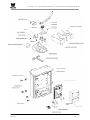
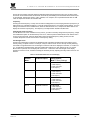
1
P: 1.866.300.1110 • F: 1.204.284.1868 • W: www.wallaceintl.com • A: 90 Lowson Crescent, Winnipeg, MB, Canada, R3P 2H8 FoldSmart DC Wallace International Reference Manual Models: FoldSmart XT, FoldSmart TT, SpeedSmart DC and SpeedSmart DC HD Revision A.13 -1- P: 1.866.300.1110 • F: 1.204.284.1868 • W: www.wallaceintl.com • A: 90 Lowson Crescent, Winnipeg, MB, Canada, R3P 2H8 Revision A.13 -2- P: 1.866.300.1110 • F: 1.204.284.1868 • W: www.wallaceintl.com • A: 90 Lowson Crescent, Winnipeg, MB, Canada, R3P 2H8 Table of Contents FoldSmart DC ______________________________________________________________ 1 Exploded Operator & Drive Unit Views _______________________________________ 2 Table of Contents___________________________________________________________ 3 Introducing FoldSmart DC___________________________________________________ 6 Intelligent Features: Smart DC Controller™________________________________________ 6 Technical Support _______________________________________________________________ 6 Installer's Check List________________________________________________________ 7 Safety Requirements________________________________________________________ 8 Important Safety Instructions_____________________________________________________ 8 Safety Standards - Installer's Responsibility _______________________________________ 8 Safety Standards - Owner/User Responsibility ____________________________________ 10 Hazardous Materials and Proper Disposal ________________________________________ 11 Secondary Entrapment Protection Sensors_______________________________________ 11 Identifying Gate System Category and Usage Class _______________________________ 13 Choosing Secondary Entrapment Protection _____________________________________ 14 Emergency Stop Button_________________________________________________________ 15 Emergency Release ____________________________________________________________ 15 Wind Load Factors & Site Prep __________________________________________________ 17 Safety Notices__________________________________________________________________ 18 Common Industrial Symbols ____________________________________________________ 18 Power_____________________________________________________________________ 19 Installing the Earth Ground______________________________________________________ 19 Wiring AC Power _______________________________________________________________ 21 Wiring 115VAC Power __________________________________________________________ 21 Wiring 208/230VAC Power_______________________________________________________ 22 Connecting DC Power __________________________________________________________ 25 Important Considerations for DC-Power Connection ______________________________ 25 Display and Menu Options _________________________________________________ 27 INITIAL SETUP _________________________________________________________________ 27 Turning Both Power Switches On ________________________________________________ 28 Using the Smart DC Controller Buttons In Menu Mode_____________________________ 30 Revision A.13 -3- P: 1.866.300.1110 • F: 1.204.284.1868 • W: www.wallaceintl.com • A: 90 Lowson Crescent, Winnipeg, MB, Canada, R3P 2H8 Configuring the Setup Menu_____________________________________________________ 31 RUN MODE________________________________________________________________ 32 Understanding Gate Status Displays _____________________________________________ 32 Using the Smart DC Controller Buttons In RUN Mode _____________________________ 32 Using the Smart DC Controller Buttons In RUN Mode _____________________________ 33 Viewing Operator Status Displays _______________________________________________ 34 USER MENU ___________________________________________________________________ 35 Adjusting the Close Timer_______________________________________________________ 36 Setting the Time and Date _______________________________________________________ 37 Setting AC Power Loss Gate Function ___________________________________________ 38 Adjusting the Display Contrast _____________________________________________ 39 INSTALLER MENU______________________________________________________________ 43 Adjusting the Gate Speed _______________________________________________________ 44 Adjusting the IES Sensitivity ____________________________________________________ 45 Reinstating Factory Defaults ____________________________________________________ 47 Enabling the Fire Department Override ___________________________________________ 47 Enabling the Fire Department Override ___________________________________________ 48 Smart DC Controller _______________________________________________________ 58 Overview of the Smart DC Controller _____________________________________________ 59 Preliminary Testing _____________________________________________________________ 60 Vehicle Detector Installation Options_____________________________________________ 61 Connecting HY-5A Vehicle Detectors_____________________________________________ 62 Installing Standard 11-Pin Box Type Vehicle Detectors ____________________________ 64 Vehicle Detector Configuration and Quick Close Mode Selection ___________________ 65 Connecting Accessory Devices__________________________________________________ 66 Manual Push-button Station _____________________________________________________ 67 User Relays - Programming Procedure ___________________________________________ 68 Gate Systems _____________________________________________________________ 70 INSERT IMAGE _______________________________________Error! Bookmark not defined. Power Requirements ___________________________________________________________ 70 Master and Slave Wiring Connections____________________________________________ 72 Master and Slave Menu Setup ___________________________________________________ 73 Reference _________________________________________________________________ 74 Connecting a Radio Receiver for Remote Open ___________________________________ 74 Revision A.13 -4- P: 1.866.300.1110 • F: 1.204.284.1868 • W: www.wallaceintl.com • A: 90 Lowson Crescent, Winnipeg, MB, Canada, R3P 2H8 Installing a MagLock or Solenoid Lock ___________________________________________ 76 Installing a Lock for 12VDC or 24VDC Systems ___________________________________ 76 Installing a Lock on 24VAC Systems _____________________________________________ 77 Installing a Lock for High Voltage Systems _______________________________________ 77 Setting the User Relay Function in the Installer Menu _____________________________ 78 Installing Vehicle Detectors and Loops___________________________________________ 79 Installing Photoelectric Sensors For Secondary Entrapment Protection Only _______ 82 Operation Notes: _______________________________________________________________ 82 Supervised Connection: ________________________________________________________ 84 Photo Eye Function: ____________________________________________________________ 84 Smart DC Controller Troubleshooting ____________________________________________ 85 Vehicle Detector and Loop Fault Diagnostics _____________________________________ 92 FoldSmart Schematics __________________________________________________________ 94 General Maintenance ______________________________________________________ 96 Smart Touch Analyze and Retrieve Tool (S.T.A.R.T.) ______________________________ 96 Setting User Account Controls __________________________________________________ 97 Electrical Controls______________________________________________________________ 97 Mechanical Maintenance ________________________________________________________ 97 Software Maintenance __________________________________________________________ 99 Drive Belt Tension and Alignment _______________________________________________ 99 DC Battery Replacement _______________________________________________________ 100 Clock Battery Replacement ____________________________________________________ 101 Revision A.13 -5- P: 1.866.300.1110 • F: 1.204.284.1868 • W: www.wallaceintl.com • A: 90 Lowson Crescent, Winnipeg, MB, Canada, R3P 2H8 Introducing FoldSmart DC Robust - An especially strong twin channel steel chassis and manual disconnect greatly improves the ability for FoldSmart to resist damage from vehicle hits on the gate. The components on the Smart DC Controller are protected by opto-isolators which shield them from power surges and lightning strikes. Power - A variable speed control board supplies a powerful, continuous 24V DC motor which drives a 600:1 gearbox providing variable speeds. The electronics, motor and gear box are rated to operate in very broad temperatures that range from -13°F to 158°F (-25°C to 70°C). FoldSmart DC is rated for gates up to 20 feet long and 1,300 pounds. Finesse - A variable rate of gate acceleration and deceleration, dependent upon gate weight and length, assures very smooth handling. Adaptable - The design incorporates left and right gate arms to assure aesthetic functionality UPS backup - Two 12V, 8 amp hour (Ah) batteries will provide a fully functional gate system (up to 300 gate cycles) when AC power is unavailable. Four user-selectable UPS modes are available. 12VDC and 24VDC are available to power access controls. Intelligent Features: Smart DC Controller™ Automatic adjustment and synchronization of bi-parting gates - The Smart DC Controller automatically adjusts the gate speed to synchronize the left and right gates so that they reach the open and close positions at the same time. Independent leaf delay adjustment for bi-parting gates is selectable in ½ second increments. Menus and User relays - The Smart DC Controller has 48 menu items to allow installer configuration of gate function and two user relays, which can be configured for 25 different functions. Independent adjustment for open and close gate speeds - An easy-to-use menu on the Smart DC Controller allows the installer to vary the open and close speed settings in a range between 10 and 15 seconds. Intelligent Inherent Entrapment Sensor (IES) - Any impediment to gate travel is sensed by the system, stopping gate movement per UL 325 Safety Standards. The intelligent system monitors gate power then adapts the IES to trip at an adjustable threshold above normal power. Improved Liquid Crystal Display (LCD) - A 32-character LCD provides increased readability for programming and troubleshooting. USB communications port - A direct connection provides accessibility to download system diagnostics and upload system configurations using the Smart Touch Analyze and Retrieve Tool (S.T.A.R.T.) software. S.T.A.R.T. software and diagnostics - With S.T.A.R.T. software loaded on a laptop computer, you have an invaluable management tool for all Smart DC operators. To download this free software, visit the Wallace International website at wallaceintl.com. Technical Support For technical support, call Wallace International at 1-866-300-1110. Obtain the serial number of your operator before calling. Refer to the blow-apart image on the inside of the front page. For information about Wallace International training for installers, maintenance personnel and end-users, refer to the company website at www.wallaceintl.com or call 1-866-300-1110. Revision A.13 -6- P: 1.866.300.1110 • F: 1.204.284.1868 • W: www.wallaceintl.com • A: 90 Lowson Crescent, Winnipeg, MB, Canada, R3P 2H8 Installer's Check List The following list provides a high level overview of the tasks involved in installing the FoldSmart DC gate system. Take a moment to review the list and check off the items as you complete the install. □ Site Prep - concrete pad location/dimensions/distance from gate, conduits and vehicle detector loops properly installed, gate bracket and linkage arm mounting considerations. □ Make sure gate installation complies with ASTM F2200 Specification for Automated Vehicular Gate Construction and UL325 Safety Standards. Install supplied WARNING signs on both sides of the gate. □ Check for compliance with local codes, site conditions, and NEC standards. □ Install operator on gate column with included hardware. □ Temporarily attach gate bracket and linkage arm(s). □ Adjust open and close limit switches through manual operation of the gate. □ Complete gate arm installation. □ Cut the excess off the over extension stop (angle iron) on the FoldSmart arm. □ Install the earth ground and AC wiring connections for AC power. □ Connect battery wire to switch. □ Complete Initial Setup Menu programming. □ Review the connections on the Smart DC Controller. □ Install Master/Slave operator connections, if the site is a bi-parting gate system. □ Attach accessory devices. □ Configure the User and Installer Menu options. Program applicable settings dependent on accessory devices installed. □ Set the Close Timer (in the User Menu), if necessary. □ Check the Smart DC Controller software version. If needed, upload the latest version from www.wallaceintl.com. See Smart Touch Analyze and Retrieve Tool (S.T.A.R.T.). □ Give a copy of the operator instructions to the end user. Show the end user how to: □ Remove the operator covers. Turn the power off and on. □ Turn the DC power switch off, which disengages the motor. □ Loosen the manual disconnect and manually push the gate(s) open & close. □ Remember to re-tighten the manual disconnect before turning the DC power switch back on and replacing the covers. □ Test the red Emergency Stop Button located on the side of the control box. □ Take photographs of the completed installation site and send them to [email protected]. Revision A.13 -7- P: 1.866.300.1110 • F: 1.204.284.1868 • W: www.wallaceintl.com • A: 90 Lowson Crescent, Winnipeg, MB, Canada, R3P 2H8 Safety Requirements Automatic gate systems provide user convenience and security. However, because these machines can produce high levels of force, it is imperative that gate system designers, installers and end users be aware of potential hazards associated with improperly designed, installed, or maintained systems. The gate system is only one component of the total gate operating system. It is the joint responsibility of the architect, site designer, purchaser, installer and end user to verify that the total system is appropriately configured for its intended use. Additionally, certain municipalities have established licensing, codes or regulations that regulate automated gate system design and installation. Consult local government agencies for up-to-date rules and regulations prior to gate system design or installation. Important Safety Instructions WARNING A moving gate can cause serious injury or death. Start the gate system only when the gate's travel path is clear. Hazards, associated with automatic gates, can be reduced with proper site design, installation, and use. Installers, maintenance crews, and owners/users must read and follow the Important Safety Instructions in this manual and review all the literature that accompanies the product. It is important that only qualified installer’s handle the installation of the FoldSmart gate system. A “qualified” installer has one of the following: A minimum of three years experience installing similar equipment. Proof of attending a Wallace International Technical Training seminar within the past three years. Significant manufacturer endorsements of technical aptitude in gate system installation and operation. Underwriter Laboratories (UL) and the American Society for Testing and Materials (ASTM) are responsible for current safety standards and regulations regarding gate systems and automated gates. To pass UL certification, all aspects of gate installation must comply with the appropriate safety standards. For the most up-to-date, ASTM F2200 Gate and Fence Standards, refer to www.astm.org. For UL 325 Safety Standard, refer to www.ul.com. Safety Standards - Installer's Responsibility Revision A.13 Study the entire contents of this manual prior to installing, operating, or maintaining the FoldSmart gate system. Taking extra time to align the gate system and verify a fully functional installation will reduce maintenance, guarantee longest system life, and ensure customer satisfaction. Verify the gate system usage class for the site. Refer to Identifying Gate Operator Category and Usage Class for gate classifications. Install FoldSmart only when the gate system class is correct for the site, size, and type of gate. Install an automatic operator only on gates that comply with ASTM F2200 Gate and Fence Standards. Screen or enclose openings in the gate per UL 325 Safety Standards. Before attaching the operator to the gate, move the gate in both directions. Make sure it is level and moves freely. A gate that swings easily reduces strain on operator components. Gravity should play no part in the opening or closing of the gate. -8- P: 1.866.300.1110 • F: 1.204.284.1868 • W: www.wallaceintl.com • A: 90 Lowson Crescent, Winnipeg, MB, Canada, R3P 2H8 Make sure there is a separate walk-through entrance nearby. Make certain a clear pedestrian path is designated and signs direct pedestrians to the walk-through gate. The automated gate entry is for vehicle use only. No one should cross the path of a moving gate. Mount access control devices beyond reach of the gate. The control devices that operate the gate must be: Located in a clear line of sight to the gate. Mounted beyond 6 feet of the gate to prevent users from touching or accessing the gate while operating the controls. People attempting to access the controls by reaching through or around the gate can be seriously injured or killed by the moving gate. Incorporate a security feature to prevent unauthorized use. The gate system must be properly grounded and the incoming power voltage must match the voltage label on the junction box. Install enough external entrapment protection sensors so that pedestrians are protected from entrapment in both directions of the gate travel and all hazard areas and possible pinch points are fully protected. Review the information found in Secondary Entrapment Protection Sensors. Install the supplied WARNING signs on the inside and outside of the gate so they are clearly visible from both sides of the gate. Installing the signs is a requirement for UL 325 compliance. Locate controls (Open, Close, Stop/Reset) where a user will have a clear view of the gate. Refer to the Emergency Stop Button. Connect radio and other remote access (nonresetting controls) to the REMOTE OPEN terminal. Connect radio and other remote access (non-resetting controls) to the RADIO OPTIONS terminals. Open and close the gate to confirm that it was properly installed and to ensure reduced risk of entrapment. Verify the clearance between the gate and adjacent structures per UL 325 Safety Standards. Have a qualified technician test the gate monthly. When you complete the installation, show the end user how to: Remove the operator covers and turn the power off and on. Turn the DC power switch off, which disengages the motor. Loosen the quick disconnect and manually push the gate(s) open & close. Remember to re-tighten the quick disconnect before turning the DC power switch back on and replacing the covers. Test the red Emergency Stop Button located on the side of the control box. NOTE Gate system instructions must be given to the owner per UL 325 Safety Standards. Revision A.13 -9- P: 1.866.300.1110 • F: 1.204.284.1868 • W: www.wallaceintl.com • A: 90 Lowson Crescent, Winnipeg, MB, Canada, R3P 2H8 Safety Standards - Owner/User Responsibility Push buttonto WARNING A moving gate can cause serious injury or death. Automatic gate systems move gates with high force. Make sure gates and gate systems are installed to reduce the risks of entrapment. Verify your gate system complies with UL 325 Safety Standards and ASTM F2200 Gate and Fence Standards. Ask for a copy of the gate system's product literature and review it. You are responsible for educating all gate system users about proper use of the automated gate system. Failure to adjust and test the gate system on a regularly maintained schedule can increase the risk of injury or death. Automatic gates are for vehicular use only; provide and maintain walkways and signs to direct pedestrians to a separate walk-through entrance. An automatic gate can start at any time without warning; always keep people away from the gate area. Never let children operate or play with gate controls. Keep all remote controls, especially radio transmitters, away from children. Do not allow children to play on or around the gate. Learn how to turn the power on and off. Learn how to manually release the gate. CAUTION Before attempting a manual release, make sure the gate is not moving. Revision A.13 WARNING signs supplied with the gate system must remain installed and clearly visible on both sides of the gate. The signs are required to maintain UL 325 compliance. Never disable the Warn Before Operate buzzer and NEVER disconnect or cut its wires. The buzzer provides an alert that the gate is about to move and it must be functional in the event of entrapment regardless of UL 325 gate usage class. Disabling the warning buzzer may increase the risk or extent of injury if entrapment occurs. Test the gate system monthly. Specifically, test the primary Inherent Entrapment Sensor (IES) and secondary entrapment protection sensors. The gate must stop upon contact with a rigid object, and stop or reverse direction, when an object activates the non-contact sensors. After adjusting the force or the limit of travel, retest the gate system. Failure to adjust and test the gate system on a regularly maintained schedule can increase the risk of injury or death. Have a professional gate installer routinely test the entire gate system and entrapment protection sensors. Have a qualified service person make repairs to gate hardware to keep the gate running smoothly. - 10 - P: 1.866.300.1110 • F: 1.204.284.1868 • W: www.wallaceintl.com • A: 90 Lowson Crescent, Winnipeg, MB, Canada, R3P 2H8 Hazardous Materials and Proper Disposal FoldSmart uses sealed, state-of-the-art Absorbed Glass Mat (AGM) batteries and highly recommends replacing used batteries with new AGM-type batteries. CAUTION The batteries used with the FoldSmart gate contain materials that are considered hazardous to the environment. Proper disposal of the battery is required by federal law. Refer to federal guidelines found in Hazardous Waste Regulations. To reduce the risk of fire or injury to persons: Observe the polarity between the batteries and charging circuit. Never mix battery sizes, types, or brands. Wallace International strongly recommends that only sealed AGM style batteries be used. Exercise care in handling batteries. Be aware that the metal found in rings, bracelets, and keys can conduct electricity, short the batteries, and cause potential injury. Do not open or mutilate the batteries. Battery cells contain corrosive materials which may cause burns and other injuries. The material within batteries is toxic. Always dispose of batteries properly. Do NOT place batteries in fire. The battery cells may explode. Follow federal guidelines for proper disposal of hazardous waste. Replace batteries according to the instructions found in DC Battery Replacement. Secondary Entrapment Protection Sensors FoldSmart is equipped with a primary, Type A, inherent entrapment sensor (IES). UL 325 Safety Standard compliance requires installation of secondary entrapment protection sensors, the number of which, depends on the entrapment hazards that exist at each particular installation. To comply with UL 325, the following external sensors may be used: Contact sensors, such as edge sensors Non-contact sensors, such as photoelectric eyes The site designer or installer can choose either photoelectric eyes or edge sensors or use these devices in combination. Whatever devices are used, protection in both the opening and closing directions of gate travel must be provided. The UL 325 Safety Standard for automatic swinging gates specifically requires that edge sensors or photoelectric eyes or a combination of both devices be installed to protect against pedestrian entrapment in BOTH directions of the gate travel and where an entrapment hazard exists. PHOTOELECTRIC EYES: One or more photoelectric eyes shall be located where the risk of entrapment or obstruction exists, such as the perimeter reachable by a moving gate. CAUTION A photoelectric eye or contact sensor is also required to protect against possible entrapment if the gate opens to a position less than 16 inches (40.6cm) from any object, such as a post or wall. Revision A.13 - 11 - P: 1.866.300.1110 • F: 1.204.284.1868 • W: www.wallaceintl.com • A: 90 Lowson Crescent, Winnipeg, MB, Canada, R3P 2H8 EDGE SENSORS: One or more edge sensors shall be located on the inner and outer leading edge of a swing gate where the risk of entrapment or obstruction exists. If the bottom edge of the swing gate is situated more than 6-inches (152 mm) above ground level at any point in its arc of travel, one or more contact sensors must be located on the bottom edge, as well. SENSOR SECURITY: A hard-wired sensor shall be located and its wiring arranged so that communication between the sensor and gate is not subjected to mechanical damage. SENSOR FUNCTION and COMMUNICATION: A sensor that transmits its signal to the gate system must be located so its signal is not impeded by building structures or other obstructions. All sensors must be installed so that they function as intended for the end-use conditions. UL 325 LISTING: The edge sensors and photo electric eyes must be tested and labelled as “Recognized Components” under UL 325 in order to be deemed acceptable for use in a gate system. Study the Important Safety Instructions and consider your specific installation to determine where the greatest entrapment risks exist. Locate edge sensors and/or photoelectric sensors accordingly. Be certain that a sufficient number of sensors are used so that pedestrians are protected from entrapment in both directions of the gate travel and all hazard areas are fully protected. Refer to the UL website at www.ul.com for the most up-to-date list of gate system safety standards (UL 325). Refer to www.astm.org for a complete list of ASTM F2200 Gate and Fence Standards. Revision A.13 - 12 - P: 1.866.300.1110 • F: 1.204.284.1868 • W: www.wallaceintl.com • A: 90 Lowson Crescent, Winnipeg, MB, Canada, R3P 2H8 Identifying Gate System Category and Usage Class The FoldSmart gate system, according to UL 325 Safety Standards, falls in the Swing Gate and Vertical Barrier Arm category for gate systems. Its usage class is determined by the area that the vehicular gate services. Four different vehicular usage classes are defined by UL 325: Class I Class I: Intended for use in a location of one to four single family dwellings or a parking area associated with one to four single family dwellings. Class II Class II: Intended for use in a commercial location or building such as a multi-family housing units (five or more single family units) hotels, garages, retail stores or other buildings servicing the general public. Class III Class III: Intended for use in an industrial location or building such as factories or loading docks or other locations not intended to service the general public. Class IV Class IV: Intended for use in guarded industrial locations or buildings such as an airport security area or other restricted access location, not servicing the general public, in which access is monitored by security personnel or via closed circuitry. Revision A.13 - 13 - P: 1.866.300.1110 • F: 1.204.284.1868 • W: www.wallaceintl.com • A: 90 Lowson Crescent, Winnipeg, MB, Canada, R3P 2H8 Choosing Secondary Entrapment Protection The site designer or installer must determine which secondary entrapment sensor devices will be installed with the FoldSmart operator to meet UL compliance. The type of entrapment sensor device systems are described below. For a complete listing of the requirements, see UL 325 Safety Standards. NOTE FoldSmart is equipped with a primary, Type A, inherent entrapment sensor (IES) that complies with UL 325. Any impediment to gate travel causes the gate to stop and reverse. Usage Class Primary Type Device Secondary Type Device Class I, II, III A B1, B2, C, or D Class IV A B1, B2, C, D, or E To comply with UL 325, refer to the chart and take the following steps: Select the Usage Class according to the gate’s locale and purpose. The required UL 325 primary Type A sensor is an integral part of the FoldSmart gate system. Based on the gate’s usage class, choose Secondary Type Devices: B1, B2, C, D, or E. To comply using B1 - install non-contact sensors (photoelectric sensor or the equivalent). To comply using B2 - install contact sensors (edge sensor device or the equivalent). To comply using a Type D device requires a CONSTANT HOLD push-button station. This CONSTANT HOLD push-button station must be the only device that opens and closes the gate. It can only be used where the gate and push button station will be monitored by personnel 24 hours a day in full view of the gate area. An automatic closing device (such as a timer, loop sensor, or similar device) must not be employed. A Warning placard stating, “WARNING - Moving Gate has the Potential of Inflicting Injury or Death - Do Not start the Gate Unless the Path is Clear” must be placed adjacent to the gate system controls. CAUTION While compliance is possible with Type C, which is a low force limiting clutch, the FoldSmart operator develops more gate actuation force than is permitted under the UL 325 Safety Standards and, therefore, its clutch cannot be considered an entrapment protection device. Similar compliance issues exist with a Type E device (audible warn before operate alarm). A Type E device is permitted as a means of secondary entrapment protection by UL 325 in Class IV applications, but it is not recommended by Wallace International because a buzzer warns, but cannot protect against possible entrapment. Wallace International highly recommends, even for Class IV use, that secondary entrapment protection (edge or photoeye sensor) devices be installed to detect possible entrapment. Revision A.13 - 14 - P: 1.866.300.1110 • F: 1.204.284.1868 • W: www.wallaceintl.com • A: 90 Lowson Crescent, Winnipeg, MB, Canada, R3P 2H8 Emergency Stop Button An emergency stop button that is accessible from the outside of the operator is a requirement for compliance with UL325 Safety Standards. The red emergency stop button on the FoldSmart operator is located on the side of the control enclosure. Pressing the emergency stop button while the gate is opening or closing disables the automatic close timer and stops gate travel. The gate travel remains stopped until the operator receives any open or close signal. Make sure all users of the gate know where the emergency stop button is located. Emergency Release Make sure to teach all users how to turn off electric power and how to move the gate manually FoldSmart allows a gate to be pushed manually if the quick disconnect bolt is removed from the actuator arm. It is recommended that you turn off DC power which disengages the motor allowing you to easily move the gate. When you turn DC power off, the following occurs: The motor disengages which keeps it from running should any relay or open/close leaf functions be set. The GATE NO LOAD (FAULT 4) may appear on the display. To manually open the gate(s), take the following steps: 1. Remove the covers and turn off. 2. Removed the quick disconnect bolt using the included key. 3. Swing the gate(s) open or close. Revision A.13 - 15 - P: 1.866.300.1110 • F: 1.204.284.1868 • W: www.wallaceintl.com • A: 90 Lowson Crescent, Winnipeg, MB, Canada, R3P 2H8 To return FoldSmart to automatic operation, take the following steps: 1. Make sure the gate(s) is not moving. 2. Reinstall the manual disconnect. 3. Flip the DC power switch ON. 4. Clear any faults by pressing STOP or RESET. Revision A.13 - 16 - P: 1.866.300.1110 • F: 1.204.284.1868 • W: www.wallaceintl.com • A: 90 Lowson Crescent, Winnipeg, MB, Canada, R3P 2H8 Wind Load Factors & Site Prep Wind load is always a factor when considering the appropriate gate for a particular site. Solid gate panels produce a larger wind load than gates with slats or open decorative features. If you are installing a gate system in high wind areas, the gate design will affect the load on the gate system. Because wind force acts the same as an obstruction, it is important that gates be designed to present a relatively low surface area for the wind to push on the gate panel. If the gate is heavy and near the weight capacity of what the gate system can handle (see specifications for FoldSmart on the back cover), make sure it has an open design that allows wind to flow through it. A solid or semi-solid gate design under certain wind load conditions may cause damage to the gate system and is not covered by the Wallace International Limited Warranty. Several factors play into the calculations of the wind load on a gate panel. To find out the maximum wind speed in areas around the United States/Canada, search for US/Cdn. government wind speed maps on the internet. If you don’t know how to calculate for wind load, ask a mechanical engineer or site architect for assistance prior to installing the gate system and gate panels. FoldSmart incorporates a primary Type-A inherent entrapment sensor (IES) into its design per UL 325 Safety Standards. (More information about adjusting the adaptive IES software can be found in this manual under Adjusting the IES Sensitivity.) When the IES trips, it sends a signal to the gate system to stop and reverse direction. This feature may be falsely triggered in excessively windy conditions because the wind itself, acting over the surface area of the gate panel, can provide the necessary force to trigger the IES. CAUTION Do not adjust IES sensitivity to accommodate for inappropriately designed gate panels. Loss of IES sensitivity increases mechanical wear on the gate hardware and the gate system. It may also pose a safety hazard. Compensating for wind loads by adjusting the IES may set the IES sensitivity to a level which, when encountering an obstruction, ignores the obstruction and fails to reverse direction. For more information, refer to Adjusting the IES Sensitivity. Revision A.13 - 17 - P: 1.866.300.1110 • F: 1.204.284.1868 • W: www.wallaceintl.com • A: 90 Lowson Crescent, Winnipeg, MB, Canada, R3P 2H8 Safety Notices The following four levels of safety notices are used where applicable within this manual; each notice contains information specific to the situation. DANGER Indicates death or serious injury will occur if the hazardous situation is not avoided. WARNING Indicates death or serious injury could occur if the hazardous situation is not avoided. CAUTION Indicates mild or moderate injury could occur if the hazardous situation is not avoided. CAUTION Indicates damage to equipment is probable if the hazardous situation is not avoided. Common Industrial Symbols The following international safety symbols may appear on the product or in its literature. The symbols are used to alert you to potential personal injury hazards. Obey all safety messages that follow these symbols to avoid possible injury or death. Attention - Take Notice Revision A.13 DANGER - Keep Away Entrapment Zone Possible Pinch Point - 18 - P: 1.866.300.1110 • F: 1.204.284.1868 • W: www.wallaceintl.com • A: 90 Lowson Crescent, Winnipeg, MB, Canada, R3P 2H8 Power Installing the Earth Ground An earth ground refers to the grounding rod and accompanying equipment ground which need to be installed to safeguard against potential electrical shock and damage to personnel and equipment. DANGER The potential for lightning discharge exists with all gates, fences and gate systems. National Electric Code (NEC) requires a separate earth ground in addition to the required equipment ground. Wallace International recommends grounding the operator with a separate earth ground connected to a ground rod to assure proper operation and shield it against electromagnetism and other electrical signals that may cause erratic operation with or damage to the Smart DC Controller. NOTE If you do not ground the operator with a separate earth ground rod, you risk voiding the Limited Warranty. For earth grounding requirements, refer to the National Fire Protection Association (NFPA) 780 - Standard for the Installation of Lightning Protection Systems/Canadian Standard. Highlights of the standard include. The ground rod is a solid copper rod: minimum requirements: ⅝" (16mm) diameter and 10 feet (3m) in length. The ground rod is driven into the earth (refer to local codes for proper depth requirements). The ground rod is electrically bonded to the chassis with a single length of un-spliced 6AWG copper wire less than 3 feet (91cm) long. Local jurisdictions may impose additional requirements above the NEC and NFPA 780. Consult the local codes and regulations regarding requirements in your area. Take the following steps to comply with NEC and NFPA 780 standards: 1. Install a grounding rod per local building codes. See Figure 2-1. 2. Attach a ring terminal to the earth ground wire (6 AWG) and terminate at the labelled grounding location in the AC junction box. Revision A.13 - 19 - P: 1.866.300.1110 • F: 1.204.284.1868 • W: www.wallaceintl.com • A: 90 Lowson Crescent, Winnipeg, MB, Canada, R3P 2H8 Figure 2-1. Properly grounding the gate system is critical to gate system performance and the life of its electrical components. Use sufficient wire size during installation. Refer to Wiring 115VAC Power or Wiring 208/230VAC Power. Revision A.13 - 20 - P: 1.866.300.1110 • F: 1.204.284.1868 • W: www.wallaceintl.com • A: 90 Lowson Crescent, Winnipeg, MB, Canada, R3P 2H8 Wiring AC Power DANGER Turn off AC power at the source (circuit breaker panel) before accessing the wires in the FoldSmart junction box. Follow facility Lock Out/Tag Out procedures. Make sure both the DC and AC power switches, on the side of the FoldSmart control box are in the off position. See Figure 2-2. WARNING Wiring of gate systems must conform to the NEC standards and comply with all local codes. If you plan to connect to 208/230VAC power, read the WARNING in Figure 2-2. The voltage selector switch on the AC Power board must be moved to the 230V position or damage to the operator will occur and void the Limited Warranty. Figure 2-2. Wiring 115VAC Power For standard 115VAC power connection: Revision A.13 Verify AC power supply wires and low voltage (12V & 24V accessory power wires) run through two separate conduits. The higher voltage from the AC power supply may cause interference and anomalies in FoldSmart operation if the high and low voltage wires are routed through the same conduit. - 21 - P: 1.866.300.1110 • F: 1.204.284.1868 • W: www.wallaceintl.com • A: 90 Lowson Crescent, Winnipeg, MB, Canada, R3P 2H8 Maximum gate system current draw is 3 Amps on a dedicated 115VAC circuit (20A dedicated circuit is recommended). Make sure proper wiring is being used. The following table shows the maximum allowable wire run from the power source to the operator for various wire sizes. Table 2-1. Wire Gauge versus Run AC Power 14 gauge wire 12 gauge wire 10 gauge wire One operator 115V 730 ft (223 m) 1200 ft (366 m) 1900 ft (579 m) Two operators 115V 460 ft (140 m) 750 ft (228 m) 1160 ft (354 m) Table 2-1 assumes a dedicated circuit with an accessory power load up to 2A. Additional loads require that the wire size be increased or the distance of the run be decreased. To connect to 115VAC power, take the following steps: 1. Make sure the AC power is turned off at its source and the DC and AC power switches on the operator are in the off position. 2. Access the input power wires and service outlet wires by removing the two Phillips-head screws that secure the high voltage junction box cover. See Figure 2-2. NOTE The service outlet wires are solid copper and are labelled and bound together to keep them separate from the AC power switch wires. 3. Terminate the power supply wires to the corresponding black and white lead wires terminated in the top of the screw terminal termination strip. 4. Terminate the equipment ground wire to the corresponding green ground wire terminated in the top of the screw terminal termination strip. 5. To activate the 115VAC service outlet, include the black and white outlet lead wires and the green ground wire in the connections made above. 6. Neatly organize all wire connections and replace the high voltage junction box cover. Secure it with the two Phillips-head screws. Wiring 208/230VAC Power CAUTION All FoldSmart operators are shipped from the factory as 115VAC units. When connecting to 208/230VAC power, the voltage selector switch on the AC power board must be moved to the 230V position or damage to the operator will occur and void the Limited Warranty. Revision A.13 - 22 - P: 1.866.300.1110 • F: 1.204.284.1868 • W: www.wallaceintl.com • A: 90 Lowson Crescent, Winnipeg, MB, Canada, R3P 2H8 For the 208/230VAC power connection: Verify AC power supply wires and low voltage (12V & 24V accessory power wires) run through two separate conduits as discussed in Wiring 115VAC Power. Maximum gate system current draw is 1.5 Amps on a dedicated 208/230VAC circuit (20A dedicated circuit is recommended). Make sure proper wiring is being used. Refer to the following table: Table 2-2. Wire Gauge versus Run for 208/230VAC AC Power 14 gauge wire 12 gauge wire 10 gauge wire One operator 208/230V 2095 ft (639 m) 3350 ft (1021 m) 5300 ft (1615 m) Two operators 208/230V 1465 ft (446 m) 2350 ft (716 m) 3750 ft (1143 m) Table 2-2 assumes a dedicated circuit. Additional loads require that the wire size be increased or the distance of the run be decreased. To connect to 208/230VAC power, take the following steps: 1. Make sure the AC power is turned off at its source and the DC and AC power switches on the operator are in the off position. Voltage selector switch set to 230V. Figure 2-3. 2. Remove the High Voltage Protection cover by unscrewing the two Phillips-head screws that secure it. 3. Toggle the voltage selector switch from 115V to 230V. Replace the High Voltage cover and secure it. See Figure 2-3. Revision A.13 - 23 - P: 1.866.300.1110 • F: 1.204.284.1868 • W: www.wallaceintl.com • A: 90 Lowson Crescent, Winnipeg, MB, Canada, R3P 2H8 4. Access the input power wires by removing the two Phillips-head screws that secure the High Voltage Junction Box Cover. See Figure 2-2. 5. Terminate the power supply wires to the corresponding black and white lead wires terminated in the top of the screw terminal termination strip. 6. Terminate the equipment ground wire to the corresponding green ground wire terminated in the top of the screw terminal termination strip. DANGER To use the service outlet with 208/230VAC, a separate neutral wire (white) must be run from the power source. Make sure the incoming power wires are sized appropriately to support the load expected on the service outlet. Follow guidelines per the National Electrical Code Article 250. 7. Neatly organize all wire connections and replace the high voltage junction box cover. Secure it with the two Phillips-head screws. 8. Place the 208V or 230V 1Ø label on the Junction Box Cover over the 115V 1Ø label. Revision A.13 - 24 - P: 1.866.300.1110 • F: 1.204.284.1868 • W: www.wallaceintl.com • A: 90 Lowson Crescent, Winnipeg, MB, Canada, R3P 2H8 Connecting DC Power To connect the DC power: 1. Turn off the DC and AC power switches. 2. Attach the red spade connector to the battery terminal on the DC power switch. Important Considerations for DC-Power Connection Since the operator is intended to run on batteries, control of the load is important. Gates that move easily and do not bind will drain less energy from the battery, preserving capacity for more cycles during a power failure. Be certain to observe polarity when connecting the batteries or adding accessories. Reversed polarity may result in a non-functional operator or damage to a component. Red (+) is positive and black (-) is negative. If shorted, the batteries will generate a very high current. The batteries are connected in a series circuit: Join the positive (+) terminal from one battery to the negative (-) terminal of the next battery. Batteries have a finite life and age more quickly when exposed to temperatures above 80°F (27°C). Battery temperatures above 104°F (40°C) are damaging and significantly shorten battery life. As the batteries age, they will progressively lose their capacity to store energy. If the total amount of back up capacity is critical, plan to replace the batteries after two years of use especially in hot climates. Properly discard used batteries. Refer to Hazardous Materials and Proper Disposal. WARNING Batteries contain sulfuric acid. Acid in your eyes, on your skin, or on your clothing can cause injury and severe burns. If batteries are dropped or damaged dispose of them properly. Batteries are rated to perform to capacity at certain temperatures. Variations in temperature affect performance of the batteries. An example of amp hour performance is shown in Table 2-3. Wallace International supplies a heater option that mounts near the battery pack, providing residual heat which guards against amp hour loss in colder climates. Table 2-3. Amp Hour - Example of Battery Performance Temperature 77°F (25°C) Revision A.13 Capacity 100 32°F (0°C) 80 -22°F (-27°C) 50 Wallace International uses a permanently sealed AGM-type battery which last much longer than wet cell batteries and needs no maintenance over its life span. Batteries are protected from over discharge by a low voltage sensing circuit. The charger circuit - 25 - P: 1.866.300.1110 • F: 1.204.284.1868 • W: www.wallaceintl.com • A: 90 Lowson Crescent, Winnipeg, MB, Canada, R3P 2H8 regulates to allow high charger output when the battery is partially discharged. The charger circuit automatically reduces the output to near zero as the batteries become fully charged. NOTE The FoldSmart operator stores all User and Installer Menu settings in non-volatile memory (EEPROM). Configurations are saved if a power loss occurs and reinstated once power is restored. Revision A.13 - 26 - P: 1.866.300.1110 • F: 1.204.284.1868 • W: www.wallaceintl.com • A: 90 Lowson Crescent, Winnipeg, MB, Canada, R3P 2H8 Display and Menu Options This section of the manual provides information about the display and menu options. It includes how to: Turn both AC and DC power switches on. Configure the Setup Menu Review how to use the Smart DC Controller Buttons in Menu Mode Review Run Mode and Gate Status Displays Access and Configure User Menu Options Adjust the Close Timer Set the Time and Date Set the AC Power Loss Gate Function Adjust the Display Contrast Access and Configure Installer Menu Options Set the Open and Close Gate Speed Adjust IES Sensitivity Enable Fire Department Access Reinstate Factory Defaults It describes what you will see on the display and explains the functionality of the buttons. User and Installer Menu charts provide information about peripheral connections and the corresponding menu items that need to be configured. INITIAL SETUP Once you’ve completed the installation of the FoldSmart operator and attached the wired accessories, you’re ready to program the operator. Two different approaches exist: Connect a laptop computer to the USB or serial (RS-232) port and upload the gate settings and set the operator menu configurations via the S.T.A.R.T. software. NOTE Use a laptop computer at your place of business to conveniently download the free S.T.A.R.T. software from www.wallaceintl.com before heading out into the field. A S.T.A.R.T. User Guide is also available online. Revision A.13 Manually navigate through the User and Installer Menus using the buttons located on the Smart DC Controller. The instructions for performing this second option are provided in this section. - 27 - P: 1.866.300.1110 • F: 1.204.284.1868 • W: www.wallaceintl.com • A: 90 Lowson Crescent, Winnipeg, MB, Canada, R3P 2H8 Turning Both Power Switches On One AC and one DC rocker power switch are located on the outside edge of the control box. Refer to Figure 3-1. 1. Turn both power switches ON. An audible beep occurs and a red light pulsates next to the OPEN button on the Smart DC Controller which indicates the system is functioning. NOTE If AC power is lost, the rate of flashing slows down. Other indicator lights are described below. 2. The software version briefly appears on the LCD display and the display settles on one of the following modes: Gate status - indicates the operator is in Run Mode. Refer to Run Mode. Usage class - indicates that the Setup Menu, which consists of four sequential displays, needs to be programmed. Refer to Configuring the Setup Menu. Error message - indicates a problem exists with the operator which needs to be resolved before the operator can function properly. Refer to Smart DC Controller Troubleshooting. Figure 3-1. NOTE The Smart DC Controller can be powered when either switch is turned on. However, the operator is a DC-powered unit and runs on its batteries. If the DC power switch is off, the operator will not function (even though the AC power switch is on). When the operator is Revision A.13 - 28 - P: 1.866.300.1110 • F: 1.204.284.1868 • W: www.wallaceintl.com • A: 90 Lowson Crescent, Winnipeg, MB, Canada, R3P 2H8 connected to AC power and the unit is turned on, the charge level of the battery is being monitored and maintained. The flashing red indicator light next to the OPEN button on the Smart DC Controller is considered the heart beat of the system. It indicates that the electronics board is receiving power. When AC power is lost, the rate of flashing slows down. Another indicator light, above the display, is multi-colored and corresponds to the action that the operator is performing: Green - the operator is stopped. Flashing yellow - the operator is running. Red - the operator has experienced an error. Multi-colored LED indicates power and gate status Red LED flashes indicating processor is working. Figure 4-2. Revision A.13 Not lit - AC power is lost. Pressing the SHOW LEDs button indicates which inputs, if any, are active. - 29 - P: 1.866.300.1110 • F: 1.204.284.1868 • W: www.wallaceintl.com • A: 90 Lowson Crescent, Winnipeg, MB, Canada, R3P 2H8 Using the Smart DC Controller Buttons In Menu Mode The buttons on the Smart DC Controller let you navigate, change, or clear the information in the display menus. Refer to Figure 3-2. The buttons with text above and below are variable function keys (VFK). Use these buttons to enter or change operational data and navigate through the User and Installer Menus. The singular use of a variable function key is dependent on operator mode. Three different modes exist: Run Mode - gate is operational awaiting commands. Refer to Using the Smart DC Controller Buttons In RUN Mode: RUN Mode. Menu Mode - motor disengages and operator commands are ignored. Data entry, menu navigation, and menu selection can be accomplished via the Controller buttons or through a S.T.A.R.T. software connection using the USB port. Fault Mode - errors, faults or alerts appear on the display. Some errors or faults can be reset with the STOP button while more serious faults require the RESET button or cycling power, and then pressing RESET. Faults indicate a need for diagnosis and resolution. Refer to Smart DC Controller Troubleshooting. Figure 3-2. Function of the Smart DC Controller Buttons in Menu Mode Revision A.13 - 30 - P: 1.866.300.1110 • F: 1.204.284.1868 • W: www.wallaceintl.com • A: 90 Lowson Crescent, Winnipeg, MB, Canada, R3P 2H8 Configuring the Setup Menu The USAGE CLASS display appears the first time power is supplied. See Figure 3-3. Note:If a gate status display appears, the Setup Menu has already been configured. Refer to Understanding Gate Status Displays. Four sequential displays present information which must be configured before FoldSmart will function. Once the configuration is complete, the information is retained even when a power loss occurs. Programming the Setup Menu is usually a onetime occurrence unless factory defaults are reinstated through the Installer Menu. Refer to Reinstating Factory Defaults. To navigate within the Setup Menu, use the SELECT, NEXT, and PREV buttons. All menu options cycle, so you eventually return to the first menu option by continually pressing the NEXT or PREV key. From the USAGE CLASS display, take the following steps: 1. Press SELECT. The two top characters blink. 2. Press NEXT. Continue to press NEXT to view all the selections. 3. When the desired selection appears, press SELECT. The blinking characters become static. 4. Press NEXT. Advance to the next menu display. 5. Continue to configure each menu display that appears. An audible beep occurs as the gate status display appears when the initial setup is complete. The operator enters Run Mode. Figure 3-3. Setup Menu Revision A.13 - 31 - P: 1.866.300.1110 • F: 1.204.284.1868 • W: www.wallaceintl.com • A: 90 Lowson Crescent, Winnipeg, MB, Canada, R3P 2H8 RUN MODE Gate status displays appear when the operator is ready and waiting for a gate operation command. When the menu display is flashing “GATE OPENING” or “GATE CLOSING” a command has been received and the operator is responding appropriately. The command may come from a variety of sources: a card reader, pushbutton remote, or recognition of a vehicle passing over a loop detector. In all cases, the operator “runs” the motor when it receives a gate operation command. Understanding Gate Status Displays Figure 3-4. Gate Status Displays Three gate status displays are shown in Figure 3-4. Each indicates the position or status of the gate. When accessing the User or Installer menus, you must begin at one of these gate status displays. NOTE To access the User or Installer menus, the motor cannot be engaged and the gate cannot be moving. Revision A.13 - 32 - P: 1.866.300.1110 • F: 1.204.284.1868 • W: www.wallaceintl.com • A: 90 Lowson Crescent, Winnipeg, MB, Canada, R3P 2H8 Using the Smart DC Controller Buttons In RUN Mode The Run Mode buttons are distinguished by the fact that their name appears above each button. The buttons with text above and below are variable function keys (VFK) and function differently depending on the mode of the operator. Three different modes exist: Run Mode - gate is operational awaiting commands. Menu Mode - motor disengages and operator commands are ignored. Menu navigation and menu: selection can be accomplished using the Smart DC Controller buttons or through a S.T.A.R.T. software connection via the USB port. Refer to Using the Smart DC Controller Buttons In Menu Mode. Fault Mode - errors, faults or alerts appear on the display. Some errors or faults can be reset with the STOP button while more serious faults require the RESET button or cycling power, and then pressing RESET. Faults indicate a need for diagnosis and resolution. Refer to Smart DC Controller Troubleshooting. Figure 3-5. Function of Smart DC Controller Buttons in Run Mode Revision A.13 - 33 - P: 1.866.300.1110 • F: 1.204.284.1868 • W: www.wallaceintl.com • A: 90 Lowson Crescent, Winnipeg, MB, Canada, R3P 2H8 Viewing Operator Status Displays Eight operator status displays appear in two second intervals and show pertinent information which provides a quick overview of the operator’s status or configurations. Refer to Figure 3-6. NOTE Items shown inside the brackets < > are variables that may change depending on operator configurations. The examples shown in Figure 3-6 may appear differently on your operator. Figure 3-6. Operator Status Displays Revision A.13 - 34 - P: 1.866.300.1110 • F: 1.204.284.1868 • W: www.wallaceintl.com • A: 90 Lowson Crescent, Winnipeg, MB, Canada, R3P 2H8 USER MENU The User Menu consists of twelve functions which can be modified using the Smart DC Controller buttons. Refer to Using the Smart DC Controller Buttons In Menu Mode. To access the User Menu, take the following steps: 1. At a gate status display, press the MENU button. Eight operator status displays scroll past and the CLOSE TIMER display appears. NOTE To access the User Menu, the operator must be in Run Mode. The motor cannot be engaged and the gate cannot be moving. 2. To bypass the operator status displays and access the User Menu, press the MENU button twice. The CLOSE TIMER display appears. In the pages that follow, a detailed view of the more commonly used menus is provided: Adjusting the Close Timer Setting the Time & Date Setting the AC Power Loss Gate Function Adjusting the Display Contrast Table 3-1 describes the User Menus, supplies the factory defaults, and references the hard-wire connections. For information on how the menu buttons function, review Using the Smart DC Controller Buttons In Menu Mode. Revision A.13 - 35 - P: 1.866.300.1110 • F: 1.204.284.1868 • W: www.wallaceintl.com • A: 90 Lowson Crescent, Winnipeg, MB, Canada, R3P 2H8 Adjusting the Close Timer The close timer assigns how many seconds will pass before the operator initiates closure of a fully opened gate after all open commands and reversing sensor inputs have ceased. Every gate operator needs to have the close timer set to a specific number of seconds unless a hard-wired closing device is connected to the unit such as a push-button station. To adjust the time (1 to 99 seconds) it takes before the operator initiates gate closure, take the following steps: 1. At a gate status display, press the MENU button twice. This accesses the User Menu and the CLOSE TIMER display appears. 3. Use the SELECT and NEXT or PREV buttons to navigate and change the number on the display. NOTE Keep the close time at zero if gate personnel operate the gate or the owner plans to use a remote control. 4. To exit the User Menu, press the MENU button. The gate status appears in the display indicating you have returned to Run Mode. Revision A.13 - 36 - P: 1.866.300.1110 • F: 1.204.284.1868 • W: www.wallaceintl.com • A: 90 Lowson Crescent, Winnipeg, MB, Canada, R3P 2H8 Setting the Time and Date A feature of the Smart DC Controller is its 24-hour, 365 day clock. Make sure it is set to the appropriate time zone. An accurate time and date allows the diagnostic log to date stamp operational data which indicates when Alerts, Faults and Errors occur. The log helps in troubleshooting and can be viewed via a laptop connected to the USB or RS232 port. For more information, refer to Smart DC Controller Troubleshooting. To set or adjust the time or date, take the following steps: 1. At a gate status display, press the MENU button twice. This accesses the User Menu and the CLOSE TIMER display appears. 2. Press NEXT or PREV until the SET CLOCK display appears. 3. Press SELECT. CL blinks. 4. Press NEXT or PREV to change the number to 1. 5. Press SELECT to accept the display. 6. The date and time display appears. Use the SELECT and NEXT buttons in the same manner as before to adjust the date and time. NOTE A date or time field must be blinking before it can be changed. 7. To accept what appears on the date and time display, press SELECT. 8. To exit the User Menu, press the MENU button. A gate status appears in the display indicating you have returned to Run Mode. NOTE A lithium coin battery supports the clock so the date and time is retained even when the main power is turned off. Replace the battery about every five years with a DL 2025, DL 2032 or CR 2025 or CR 2032 battery. Refer to Clock Battery Replacement. Revision A.13 - 37 - P: 1.866.300.1110 • F: 1.204.284.1868 • W: www.wallaceintl.com • A: 90 Lowson Crescent, Winnipeg, MB, Canada, R3P 2H8 Setting AC Power Loss Gate Function The setting in the AC LOSS display determines what action the operator performs during an AC power loss. The settings help reduce drain on the battery. You can choose between four settings depending on customer preferences. Normal gate functions continue until the system detects a battery voltage drop below 21V. DEAD BATTERY appears on the display and the gate automatically opens. Any pushbutton CLOSE command will close the gate and any open command will re-open the gate. If the battery continues to diminish and the system detects 18V or less, the system initiates an automatic open cycle. Any new open or close command is ignored and the LCD appears blank. The system remains in this disabled state until reset or the battery recovers to 24V. Normal gate functions continue until the system detects a battery voltage drop below 21V.DEAD BATTERY appears on the display and the gate automatically closes. The gate can be opened by a special sequence of a STOP input followed by an OPEN pushbutton or directly opened with the Fire Department Open command. Any push-button CLOSE command will close the gate. If the battery continues to diminish and the system detects 18V or less, the system initiates an automatic open cycle if not already on a limit. Any new open or close command is ignored and the LCD appears blank. The system remains in this disabled state until reset or the battery recovers to 24V. The operator automatically opens the gate five seconds after it detects an AC power loss. The gate remains open until AC power is restored. Any push-button CLOSE command will close the gate and any open command will open the gate. When the battery voltage drops below 21V or less, the system initiates an automatic open cycle. The gate will remain open until the battery recovers to 24V. The operator initially does nothing after it detects AC power loss until it receives an open command. Once an open command is received, the operator opens and remains in that state. Any push-button CLOSE command will close the gate and any open command will open the gate. When the battery voltage drops below 21V or less, the system initiates an automatic open cycle. The gate will remain open until the battery recovers to 24V. To designate what you want the operator to do during an AC power loss, take the following steps: 1. At a gate status display, press the MENU button twice. This accesses the User Menu and the CLOSE TIMER display appears. 2. Press NEXT until the AC LOSS display appears. 3. Use the SELECT and NEXT buttons to navigate and change the number on the display. Review Using the Smart DC Controller Buttons In Menu Mode. 4. To exit the User Menu, press the MENU button. A gate status appears in the display indicating you have returned to Run Mode. Revision A.13 - 38 - P: 1.866.300.1110 • F: 1.204.284.1868 • W: www.wallaceintl.com • A: 90 Lowson Crescent, Winnipeg, MB, Canada, R3P 2H8 Adjusting the Display Contrast The display contrast can be adjusted from 1 to 9 to increase visibility and ease of use. It is set at the factory to level 5. The text becomes darker as you go up the scale. To adjust the contrast (1 to 9), take the following steps: 1. At a gate status display, press the MENU button twice. This accesses the User Menu and the CLOSE TIMER display appears. 2. Press NEXT until the LCD CONTRAST display appears. 3. Use the SELECT and NEXT buttons to navigate and change the number on the display. 4. To exit the User Menu, press the MENU button. A gate status appears in the display indicating you have returned to Run Mode. Revision A.13 - 39 - P: 1.866.300.1110 • F: 1.204.284.1868 • W: www.wallaceintl.com • A: 90 Lowson Crescent, Winnipeg, MB, Canada, R3P 2H8 Table 3.1. Smart DC Controller - User Menu Functions Revision A.13 - 40 - P: 1.866.300.1110 • F: 1.204.284.1868 • W: www.wallaceintl.com • A: 90 Lowson Crescent, Winnipeg, MB, Canada, R3P 2H8 Table 3.1. Smart DC Controller - User Menu Functions Revision A.13 - 41 - P: 1.866.300.1110 • F: 1.204.284.1868 • W: www.wallaceintl.com • A: 90 Lowson Crescent, Winnipeg, MB, Canada, R3P 2H8 Table 3.1. Smart DC Controller - User Menu Functions Revision A.13 - 42 - P: 1.866.300.1110 • F: 1.204.284.1868 • W: www.wallaceintl.com • A: 90 Lowson Crescent, Winnipeg, MB, Canada, R3P 2H8 INSTALLER MENU The Installer Menu consists of several functions which can be modified using the Smart DC Controller buttons or configured through the use of a laptop computer and the S.T.A.R.T. software available from the Wallace International website. The Installer Menu options provide more advanced configurations for the FoldSmart gate system. Access to the Installer Menu is through the User Menu. The navigational buttons are the same in both menu modes. To review how to use the navigational buttons on the Smart DC Controller, refer to Using the Smart DC Controller Buttons In Menu Mode. NOTE To access the User or Installer menus, the operator must be in Run Mode with a gate status showing on the display. The motor cannot be engaged and the gate cannot be moving. To access the Installer Menu, take the following steps: NOTE Four menu items, Usage Class, Gate Handing, Gate Weight, and Gate Length must be configured before the operator will function. Refer to Configuring the Setup Menu. In the pages that follow, a detailed view of the more commonly used menus is provided. Adjusting the Open Speed Adjusting the Close Speed Adjusting the IES Sensitivity Enabling the Fire Department Override Reinstating Factory Defaults Table 3-2 describes the Installer Menus, supplies the factory defaults, and references the hard-wire connections. For information on how the menu buttons function, review Using the Smart DC Controller Buttons In Menu Mode. Revision A.13 - 43 - P: 1.866.300.1110 • F: 1.204.284.1868 • W: www.wallaceintl.com • A: 90 Lowson Crescent, Winnipeg, MB, Canada, R3P 2H8 Adjusting the Gate Speed The gate speed designates how quickly the gate opens and closes. The available range from 1 to 10 varies the speed of the motor and the gate speed increases as you go up the number scale. The adjustable speed range is approximately 15 seconds to 10 seconds. NOTE Two displays, one for OPEN SPEED the other for CLOSE SPEED, exist in the Smart DC Controller. The steps involved in changing the open speed are shown below. The steps to set the close speed are the same, you just need to access at the CLOSE SPEED display. The factory defaults for both are set to a level 5, a mid-range setting. To adjust the gate speed (1 to 10), take the following steps: 1. At a gate status display, press the MENU button twice. This accesses the User Menu and the CLOSE TIMER display appears. 2. Simultaneously, press the OPEN and RESET buttons to enter the Installer Menu. Release the buttons and the USAGE CLASS display appears. It is the first item in the Installer Menu. 3. Press NEXT until the OPEN SPEED (or CLOSE SPEED) display appears. The factory default setting is 5. A speed setting of 1 slows the gate travel speed to open or close in approximately 15 seconds. A speed setting of 10 increases gate travel and opens or closes in approximately 10 seconds. 4. Use the SELECT and NEXT buttons to navigate and change the speed setting on the display. 5. To exit the Installer Menu, press the MENU button. The gate status appears in the display indicating you have returned to Run Mode. Revision A.13 - 44 - P: 1.866.300.1110 • F: 1.204.284.1868 • W: www.wallaceintl.com • A: 90 Lowson Crescent, Winnipeg, MB, Canada, R3P 2H8 Adjusting the IES Sensitivity FoldSmart uses a primary Type-A inherent entrapment sensor (IES) per UL325 Safety Standards. A solid immovable object blocking the gate will trip the IES and cause the operator to stop and reverse (for two seconds) and enter safe mode. The adaptive IES software monitors the average running motor current while the gate is in motion and reverses the gate when the current exceeds an automatically selfadapting average. The IES display, accessed through the Installer Menu, allows you to input a number between 0 and 9. The settings (0 through 6) allow an increasingly higher threshold (amount of headroom) above the average current draw before tripping. For IES settings 7 through 9, the current limit is a fixed relatively high value before the IES will be tripped. The factory setting is 2, which is adequate for most sites. CAUTION Avoid setting the IES sensitivity to a fixed level (7 - 9 setting). The high motor current required for the IES to trip could cause severe injury or death to people caught in the moving gate. For IES settings (0 through 6), the motor current is continually being measured and the IES threshold automatically set to trip at the average current plus the additional “headroom” provided by the IES setting selected. To prevent false IES trips, the software boosts the IES current threshold for one gate cycle after an IES event, then returns to the normal sensitivity threshold. Over time, a gate may sag or a hinge begin to fail or other site issues, such as wind loading, can occur. As the gate hardware ages and becomes stiffer, the FoldSmart motor current increases. A failing hinge or other gate condition which causes excessive drag may create the need to use a higher IES setting level.The higher settings should only be used on a TEMPORARY basis until the gate sag or bad hinge is repaired so the gate swings smoothly with minimum resistance. Revision A.13 - 45 - P: 1.866.300.1110 • F: 1.204.284.1868 • W: www.wallaceintl.com • A: 90 Lowson Crescent, Winnipeg, MB, Canada, R3P 2H8 NOTE When changing the IES setting, consider the site design and vehicular gate traffic. It is recommended that you use the most sensitive setting while still allowing for reliable gate operation. Examples of conditions which affect IES sensitivity include: Gate design - Do not use a solid panel gate design in areas of high wind. Though a higher IES setting may compensate for a minimal amount of wind load, do not use it to compensate for poor site planning and gate design. Refer to Wind Load Factors & Site Prep. If you have gate panels that are open and present little wind resistance, the deviation from the average current will be relatively small and you can use a more sensitive (lower) IES setting. Gate condition - Over time, a gate may sag or a hinge begin to fail. Gate hinges will deteriorate more rapidly near salty sea air. For these issues, you may want to use a higher (less sensitive) IES setting until repairs are made. If gate hardware is an issue, upgrade the gate hardware to reduce resistance and increase the longevity of the gate and gate operator. To adjust the IES sensitivity, take the following steps: 1. At a gate status display, press the MENU button twice. This accesses the User Menu and the CLOSE TIMER display appears. 2. Simultaneously, press the OPEN and RESET buttons to enter the Installer Menu. Release the buttons and the USAGE CLASS display appears. It is the first item in the Installer Menu. 3. Press NEXT until the IES SENSITIVITY display appears. The factory default setting is 2. CAUTION Avoid setting the IES sensitivity to a fixed level (7 - 9 setting). The high motor current required for the IES to trip could cause severe injury or death to people caught in the moving gate. 4. Use the SELECT and NEXT buttons to navigate and change the number on the display. 5. To exit the Installer Menu, press the MENU button. The gate status appears in the display indicating you have returned to Run Mode. If errors occur due to IES issues, SAFE MODE or ENTRAPMENT MODE will appear on the display. For more information about troubleshooting, refer to Table 6-1 in the “Reference” section. Revision A.13 - 46 - P: 1.866.300.1110 • F: 1.204.284.1868 • W: www.wallaceintl.com • A: 90 Lowson Crescent, Winnipeg, MB, Canada, R3P 2H8 Reinstating Factory Defaults Twelve menu configurations are available in the User Menu. Another 32 items in the Installer Menu let you customize the operator depending on the number of attached accessories and your customer’s needs. CAUTION Reinstating factory default clears ALL menu display settings stored in the operator and returns them to factory defaults. It is recommended that you save the menu settings before reinstating factory defaults. You can write the settings in a notebook or, if you have a laptop computer, you can use HySecurity’s S.T.A.R.T. software and download the menu settings as part of the diagnostic log. To reinstate factory defaults, take the following steps: 1. At a gate status display, press the MENU button twice. This accesses the User Menu and the CLOSE TIMER display appears. 2. Simultaneously, press the OPEN and RESET buttons to enter the Installer Menu. 3. Release the buttons and the USAGE CLASS display appears. It is the first item in the Installer Menu. 4. Press NEXT until the FACTORY DEFAULTS display appears. The factory default setting is 0. 5. Use the SELECT and NEXT buttons to navigate and change the number on the display to 1. NOTE When you press SELECT to accept FD 1, the factory settings are reinstated immediately and the menu display returns to the initial Setup Menu. The gate operator will not run until all four sequential menu parameters are entered: Usage Class, Gate Handing, Gate Weight, and Gate Length. Refer to Configuring the Setup Menu. Revision A.13 - 47 - P: 1.866.300.1110 • F: 1.204.284.1868 • W: www.wallaceintl.com • A: 90 Lowson Crescent, Winnipeg, MB, Canada, R3P 2H8 Enabling the Fire Department Override Many counties and cities require a Fire Department override system for gate operators. The fire department’s alert system is a separate unit that must be connected to the FoldSmart DC Controller. The FIRE DEPARTMENT OPEN option must be properly configured through the Installer Menu before the operator will recognize the alert system. To enable the Fire Department Override, take the following steps: 1. Connect the contact NO from the alert system or key switch to the following Smart DC Controller terminals: EMERG OPEN +24V 2. Configure the Installer Menu. At a gate status display, press the MENU button twice. This accesses the User Menu and the CLOSE TIMER display appears. 3. Simultaneously, press the OPEN and RESET buttons to enter the Installer Menu. Release the buttons and the USAGE CLASS display appears. It is the first item in the Installer Menu. 4. Press NEXT until the FIRE DEPARTMENT OPEN display appears. The factory default setting is 0. 5. Use the NEXT button to change the number on the display to 1 and then press SELECT. To exit the Installer Menu, press the MENU button. The gate status appears in the display indicating you have returned to Run Mode. Revision A.13 - 48 - P: 1.866.300.1110 • F: 1.204.284.1868 • W: www.wallaceintl.com • A: 90 Lowson Crescent, Winnipeg, MB, Canada, R3P 2H8 Table 3-2. Smart DC Controller - Installer Menu Functions Revision A.13 - 49 - P: 1.866.300.1110 • F: 1.204.284.1868 • W: www.wallaceintl.com • A: 90 Lowson Crescent, Winnipeg, MB, Canada, R3P 2H8 Table 3-2. Smart DC Controller - Installer Menu Functions Revision A.13 - 50 - P: 1.866.300.1110 • F: 1.204.284.1868 • W: www.wallaceintl.com • A: 90 Lowson Crescent, Winnipeg, MB, Canada, R3P 2H8 Table 3-2. Smart DC Controller - Installer Menu Functions Revision A.13 - 51 - P: 1.866.300.1110 • F: 1.204.284.1868 • W: www.wallaceintl.com • A: 90 Lowson Crescent, Winnipeg, MB, Canada, R3P 2H8 Table 3-2. Smart DC Controller - Installer Menu Functions Revision A.13 - 52 - P: 1.866.300.1110 • F: 1.204.284.1868 • W: www.wallaceintl.com • A: 90 Lowson Crescent, Winnipeg, MB, Canada, R3P 2H8 Table 3-2. Smart DC Controller - Installer Menu Functions Revision A.13 - 53 - P: 1.866.300.1110 • F: 1.204.284.1868 • W: www.wallaceintl.com • A: 90 Lowson Crescent, Winnipeg, MB, Canada, R3P 2H8 Table 3-2. Smart DC Controller - Installer Menu Functions Revision A.13 - 54 - P: 1.866.300.1110 • F: 1.204.284.1868 • W: www.wallaceintl.com • A: 90 Lowson Crescent, Winnipeg, MB, Canada, R3P 2H8 Table 3-2. Smart DC Controller - Installer Menu Functions Revision A.13 - 55 - P: 1.866.300.1110 • F: 1.204.284.1868 • W: www.wallaceintl.com • A: 90 Lowson Crescent, Winnipeg, MB, Canada, R3P 2H8 Table 3-2. Smart DC Controller - Installer Menu Functions Revision A.13 - 56 - P: 1.866.300.1110 • F: 1.204.284.1868 • W: www.wallaceintl.com • A: 90 Lowson Crescent, Winnipeg, MB, Canada, R3P 2H8 Table 3-2. Smart DC Controller - Installer Menu Functions Revision A.13 - 57 - P: 1.866.300.1110 • F: 1.204.284.1868 • W: www.wallaceintl.com • A: 90 Lowson Crescent, Winnipeg, MB, Canada, R3P 2H8 Smart DC Controller This section provides information about the Smart DC Controller board; its inputs for peripheral connections and its monitoring capabilities. This section explains how to: 1. Review the connections on the Smart DC Controller 2. Perform a Preliminary Test of the components 3. Connect Vehicle Detectors 4. Connect Accessory Devices Entrapment Sensor Connections Access Controls Manual Push-button Station User Relays Figure 4-1. Revision A.13 - 58 - P: 1.866.300.1110 • F: 1.204.284.1868 • W: www.wallaceintl.com • A: 90 Lowson Crescent, Winnipeg, MB, Canada, R3P 2H8 Overview of the Smart DC Controller The Smart DC Controller uses LED’s to indicate active inputs when AC power is present. For operators that use only DC power, you can push a button to show the active inputs. This button is at the bottom left corner near the EMERG OPEN input. On a new operator no active inputs should appear until external accessories and wiring are attached. If any inputs are active before connecting external wiring, refer to Smart DC Controller Troubleshooting. Figure 4-2. Smart DC Controller Board Revision A.13 - 59 - P: 1.866.300.1110 • F: 1.204.284.1868 • W: www.wallaceintl.com • A: 90 Lowson Crescent, Winnipeg, MB, Canada, R3P 2H8 Preliminary Testing All the control device inputs listed in Table 4-1 are shown as a single input. The second wire is connected to a Common Terminal Bus (1 - 8) on the Smart DC Controller board. The Fire Department Open input is an exception and requires a +24 Volt input as well as activation in the Installer Menu. For convenience a +24V terminal is located next to the EMERG OPEN terminal. Refer to Figure 4-2. Table 4-1. Smart DC Controller Board Inputs Terminal No. Input Name Use 1- 8 Common Terminal All user inputs are energized when connected to common except Emergency Open. 9 Stop * push button Normally Closed (N.C.). input. Jumper to Common if not being used. 10 Open * push Button Normally Open (N.O.) input. Not for radio or remote access controls. 11 Close push button N.O. input. Connection for a close push-button. 12 Remote Open and Radio Control N.O. input. For radio / remote open device - Program to also Close using Smart DC Installer Menu. 13 Partial Open Not used in swing gate operators. 14 Photo Eye Open direction N.O. input. Connection for Photo Eye Open direction. Can be changed to a supervised Normally Closed (N.C.) contact through the Installer Menu. 15 Photo Eye Close direction N.O. input. Connection for Photo Eye Close direction. Can be changed to a supervised Normally Closed (N.C.) contact through the Installer Menu. 16 Free Exit Vehicle Detector N.O. input. Connection for free exit vehicle detector. 17 Block Free Exit vehicle detector or Close Timer N.O. input. Free Exit is only disabled if Close Limit Switch is tripped. If the gate is partially opened, the Free Exit detector will trigger the gate to open fully. The input can be converted in the Installer Menu to alternately disable the Close Timer. 18 Inside Obstruction Vehicle Detector N.O. input. Inside reversing loop. 19 Outside Obstruction Vehicle Detector N.O. input. Outside reversing loop. 20 Center Loop (Shadow) Vehicle Detector N.O. input. Shadow function used for Swing gates only. 21 Edge Sensor N.O. input. One input works for both directions of travel. It can be changed to N.C. contact through the Installer Menu. 22 Photo Eye Common When the Photo Eye Open and Photo Eye Closed common wires are connected to this terminal, the photo eyes energize only when the motor runs. Use these terminals to preserve battery power. 23 +24V DC Convenient 24VDC power for photo eyes or the Emergency Open input. 24 Emergency Open (Fire Dept.Open) ** N.O. input. The Emergency Open must be enabled via the Installer Menu. It is energized by connecting to the +24V terminal above it. The EMERG OPEN overrides photo eye & edge sensor commands. *Do not connect an external control to the STOP or OPEN inputs unless the controls are located in clear view of the entire gate area. Use the RADIO OPEN input or RADIO OPTIONS spade connections for all out-of-sight controls, such as a telephone entry or radio operated controls. **The Fire Department Open control must be keyed or guarded so that it can only be used by authorized personnel. Revision A.13 - 60 - P: 1.866.300.1110 • F: 1.204.284.1868 • W: www.wallaceintl.com • A: 90 Lowson Crescent, Winnipeg, MB, Canada, R3P 2H8 Vehicle Detector Installation Options The Smart DC Controller provides a feature-rich interface to four different vehicle detector inputs. NOTE Standard box type 11 pin (24 Volt DC or 24 Volt AC) vehicle detectors may be connected in the traditional manner as described in Installing Standard 11-Pin Box Type Vehicle Detectors. HySecurity’s custom HY-5A mini-detector module (Figure 4-3) plugs directly into the Smart DC Controller Board making field installation much faster plus providing a large performance benefit. The detector communicates with the Smart DC Controller microprocessor to achieve the following benefits over common box type detectors: Loop frequency is automatically set and monitored by the Smart DC Controller. Very low power draw, which is important for maximum UPS capability during a power failure. Cross-talk between multiple loops is impossible. Best operating frequency for each loop is automatically selected. Loop frequency and call strength can be reported on the Smart DC Controller display. Loop malfunctions are reported and stored by the Smart DC Controller. Most detector or loop faults that can occur are reported and presented on the Smart DC Controller display. It is not mandatory to use two separate detectors for inner and outer obstruction detection, however the benefits of using this additional detector are great. Several new features are possible, such as second vehicle tailgating detection, loitering alert, and selectable non-reversing options. Sensitivity Dial Adjustments Status LED Standoff Supports Loop Wire Connections Figure 4-3. HY-5A Vehicle Detector Module Revision A.13 - 61 - P: 1.866.300.1110 • F: 1.204.284.1868 • W: www.wallaceintl.com • A: 90 Lowson Crescent, Winnipeg, MB, Canada, R3P 2H8 There are four vehicle detector inputs available on the Smart DC Controller as well as via the direct plug in modules. The vehicle detector input functions are as follows: Free Exit Loop Detector - This opens a fully closed gate. Outside Obstruction Loop Detector (Out Obs Loop) - This is for the outside reversing loop. Inside Obstruction Loop Detector (In Obs Loop) - This is for the inside reversing loop. Center Loop Detector - This is also known as a Shadow Loop and is used for swing gates only to prevent a gate from starting open or closed when a vehicle is in the path of the gate. NOTE Use of any combination of HY-5A detectors and box detectors is acceptable. On occasion, multiple obstruction detectors may be mandatory. For example, an area greater than 200 square feet (61 square meters) of loop cannot be connected to any one detector because the sensitivity becomes inadequate. Connecting HY-5A Vehicle Detectors Install the HY-5A Vehicle Detector modules, one at a time, according to the following procedure: 1. Turn off both AC and DC power switches. 2. Insert the locking end of the two white plastic standoffs into the mounting holes on the detector. 3. Plug the detector into the appropriate socket along the right edge of the Smart DC Controller board. Be careful to align the six detector pins into the socket correctly (the screws for tightening the terminals should face toward the board), and then snap the standoffs into the holes in the control box. 4. Route the loop wires through the holes provided in the control box and connect the loop leads to the two terminals on the HY-5A detector. Tighten the terminal screws securely. 5. To enable the detector, turn on power. The detector will immediately tune if it is connected to loops. Make sure no cars or other metal objects are over the loops. 6. Repeat Steps 1 through 5 for each HY-5A detector. 7. If the detector module is unplugged after it is enabled, a communications alert (ALERT 10) will be triggered; if the fault continues an error message, ERROR 3 “Detector Failed” is displayed. NOTE If there is any detector fault, the gate system functions as if the detector is triggered. 8. 9. Revision A.13 Pressing the RESET button: Clears any errors Tunes the detectors on connected loops Un-installs any detectors that have been removed The Smart DC Controller automatically governs frequency selection for all HY-5A detector modules. This simplifies installation and guarantees that there is no cross-talk between multiple - 62 - P: 1.866.300.1110 • F: 1.204.284.1868 • W: www.wallaceintl.com • A: 90 Lowson Crescent, Winnipeg, MB, Canada, R3P 2H8 loops. The frequency can also be manually selected; if this is required, refer to the Table 3-2 "Smart DC Controller - Installer Menu Functions" on page 49. 10. Sensitivity is the only adjustment available on the detector itself. Generally, sensitivity does not need to be increased unless the loop is large or there are multiple loops connected to one detector. NOTE Do not exceed more than 200 square feet (61 square meters) of loop area to one detector. If required, adjust the sensitivity using the rotary switch which has the following eight settings: 0 = Low with boost (See NOTE.) 1 = Normal with boost (See NOTE.) 2 = Medium with boost (See NOTE.) 3 = High with boost (See NOTE.) 4 = Low without boost 5 = Normal without boost 6 = Medium without boost 7 = High without boost NOTE A boost feature is applied for settings 0 through 3. Boost increases the sensitivity during a call and is useful for maintaining continuous detection if the signal becomes weak (such as with tractor-trailer trucks). Sensitivity settings 4 through 7 are the same as 0 through 3, but without the boost feature. 11. Vehicle detector functions are configurable through the Installer Menu as described in Table 4-2. Table 4-2. Vehicle Detector - Configurable Functions Installer Menu Setting Options (Bold - Default) Display Meaning OR 1 Outside Obstruction loop detector function 0 = Pause closing only 1 = Enable reversing to open IR 1 Inside Obstruction loop detector function 0 = Pause closing only 1 = Enable reversing to open HD 1 Center Loop detector function 0 = Hold open only 1 = Hold open and Hold closed Revision A.13 - 63 - P: 1.866.300.1110 • F: 1.204.284.1868 • W: www.wallaceintl.com • A: 90 Lowson Crescent, Winnipeg, MB, Canada, R3P 2H8 DL 1 Vehicle detector logic 1 = Standard (Close Timer does not begin counting until all loops have cleared) 2 = Quick close (Close Timer can count to zero, even while loops are active, so the gate will close as soon as the loops are clear) 12. The outside and inside Obstruction Loop Detectors are factory configured to fully re-open the gate as a default setting. In the Installer Menu, each detector can individually be set so that when the gate is closing there is only a pause if triggered. To change the setting, go to the menu OR or IR item and set to 0. Installing Standard 11-Pin Box Type Vehicle Detectors If standard 11-pin box type vehicle detectors are to be used, perform the following procedure. 1. If there is sufficient space, install the sockets in the control box; if not, then install them in a separate external housing. Figure 4-4 is for general reference only. NOTE Carefully consider your peripheral connections. Any peripheral device required for safe gate operation should be attached 24VDC in case of an AC power outage. Additionally, box detectors with relays require five times more power than HY-5A detectors, therefore UPS battery life will be extended if using HY-5A detectors. 2. Connect 24 Volt power to the detector. Connect Pin No. 1 to a 24VAC or 24VDC terminal and Pin No. 2 to common. 3. Connect output Pin No. 6 to the Common Bus and output Pin No. 5 to one of the four detector terminal inputs (depending upon the detector function required) on the Smart DC Controller. 4. If multiple detectors are used, route the power wires and common wire from socket to socket (daisy-chaining) rather than individually running each wire to the same location. See Figure 4-4. The only wires that are separate are the output wire to the Smart DC Controller and the detector loop input wires. NOTE Always keep the detector loop wires well twisted at all places beyond the area of the loop. The lead in portion sealed in a saw cut does not need to be twisted so long as the wires are encapsulated in loop sealant and cannot move. Refer to Installing Vehicle Detectors and Loops. Revision A.13 - 64 - P: 1.866.300.1110 • F: 1.204.284.1868 • W: www.wallaceintl.com • A: 90 Lowson Crescent, Winnipeg, MB, Canada, R3P 2H8 24VAC or 24VDC Connect detector to match its voltage rating Figure 4-4. Standard 11-Pin Box Type Vehicle Detector Vehicle Detector Configuration and Quick Close Mode Selection The Standard Quick Close modes are selectable in the Installer Menu. Refer to Table 3-2. The two selectable modes are described as follows: Mode 1 (Default) An input from either the Free Exit, Outside Obstruction Loop, Inside Obstruction Loop or the Center Loop will hold the gate open, reset the close timer, and block all close inputs. Mode 2 Same function as Mode 1, except the close timer can count to zero even with the Free Exit, Outside Obstruction Loop, Inside Obstruction Loop or the Center Loop detector inputs active. If the close timer has counted to zero, the gate will close when all detector inputs are clear. Revision A.13 - 65 - P: 1.866.300.1110 • F: 1.204.284.1868 • W: www.wallaceintl.com • A: 90 Lowson Crescent, Winnipeg, MB, Canada, R3P 2H8 Connecting Accessory Devices All accessories require a minimum of two connections on the Smart DC controller: a device input a Common Bus Terminal (COM) Devices, such as gate edge sensors and photoelectric beams, must be installed to protect against entrapment. These secondary entrapment protection devices are required so the gate installation is in compliance with UL 325 Safety Standards. Figure 4-5 illustrates how to connect different sensor devices to the Smart DC Controller. Figure 4-5. Entrapment Sensors & Accessory Connections Revision A.13 - 66 - P: 1.866.300.1110 • F: 1.204.284.1868 • W: www.wallaceintl.com • A: 90 Lowson Crescent, Winnipeg, MB, Canada, R3P 2H8 Manual Push-button Station A manual push-button station controls the gate system and opens, stops, and closes the gate. It is most often used by a guard in a 24-hour guard station. An example of the push-button station connections on FoldSmart is shown in Figure 4-6. CAUTION Make sure the manual push-button station in within site of the gate, a distance (six foot, 1.8m minimum) away from the gate’s moving parts, and out of reach of children. Figure 4-6. Manual Push-button Station Connection Revision A.13 - 67 - P: 1.866.300.1110 • F: 1.204.284.1868 • W: www.wallaceintl.com • A: 90 Lowson Crescent, Winnipeg, MB, Canada, R3P 2H8 User Relays - Programming Procedure The Smart DC Controller is able to interface with many types of external devices through the use of two userprogrammable output relays. All of the user relay functions identified and described in Table 4-3 are accessible in the Installer Menu. NOTE The User Relays will operate normally to less than 18VDC. The USER 2 RELAY is rated for DC only up to 48V and does not have an N.C. (normally closed) connection. Use the Smart DC Controller buttons to program the user relays according to the following steps: 1. Select the relay you wish to use. 2. Enter the appropriate function using the associated number listed in the table. Table 4-3. User-Programmable User Relays - Function Options No. Name 1 Close limit output Creates an interlock signal to another operator’s interlock input, or simply to indicate that the gate is secure. The relay is released when the fully-closed limit switch is tripped. The relay is energized when the fully-closed limit is released. (Any open command energizes the relay.) 2 Close limit pulse output Used in a sequenced system to command a second machine to close. Generates a brief pulsed output that occurs when the close limit is triggered. 3 Open limit output Indicates a full-open position. This output becomes active when an open-limit is triggered and releases when the open-limit is released. 4 Open limit pulse output Trips a sequenced barrier arm gate operator to open. Generates a brief pulsed-output when the open-limit is triggered. An additional pulse is also generated with any new open command even when the gate is already fully-opened. 5 Warn before/during operate output Controls an external warning device. This output operates at the same time as the internal warn before operate buzzer. 6 Gate Lock output Controls external solenoid locks or magnetic locks. In both directions of travel, this output is activated about 7/10ths of a second before the operator starts moving the gate and remains active while moving as well as for a few seconds after stopping. 7 Gate forced open output Activated if the gate is forced off the closed limit switch and operator is not able to restore the gate to full closed within four seconds. This alarm resets itself in 30 seconds. Note: FA - FORCE OPEN ALERT must be set to 1 in the User Menu. 8 Gate open too long output Activates when the gate is open longer than a user-selected period of time. Adjustable from 0 delay to 135 seconds delay in 15-second time increments. Note: TL - OPEN TIME ALERT adjustments can be made in the Installer Menu. 9 Safety Mode Alert output Activated when system is in the Safety Mode or the Entrapment Mode. Safety Mode occurs upon an impact with an obstruction. Entrapment Mode means the gate is stopped and occurs if the internal inherent sensor triggers while the system is in the Safety Mode. 10 Entrapment Mode Alert output Activated only when system is in the Entrapment Mode. 11 Unauthorized Vehicle Entry output Activated when a second vehicle enters from the outside without a valid input from an access control device. This output releases when an access control input signals open or the gate reaches the close limit position. 12 Outside Obstruction Vehicle Detector output Interlocks an entry device to prevent pedestrian use. This output is active whenever the Outside Obstruction Loop Detector is tripped. Revision A.13 Description - 68 - P: 1.866.300.1110 • F: 1.204.284.1868 • W: www.wallaceintl.com • A: 90 Lowson Crescent, Winnipeg, MB, Canada, R3P 2H8 Table 4-3. User-Programmable User Relays - Function Options (Continued) No. Name 13 Loitering Alert Indicates a vehicle or loitering on the Outside Obstruction Loop. Adjustable from 0 delay to 135 seconds delay in 15-second time intervals. Note: LT - LOITERING ALERT adjustments can be made in the Installer Menu. 14 Gate nearing full travel output Activated when the gate is three feet from full travel in both the open and close directions. This output is used to reduce the sensitivity of a proximity sensor near the ends of gate travel. 15 Gate Failure output Activated to report occurrence of a problem. Indicates the system is in an Error Mode, Fault Mode or Entrapment Mode. If active, the gate is disabled. 16 Motor Running output Active when the motor is running and the gate is in motion. 17 AC Power Failure output This relay is normally energized and drops with loss of AC power. 18 DC Power Failure output Activated when the battery power is very low, but the output ceases when the battery is dead. The relay is triggered when the battery is less than 20 Volts. 19 Flasher Relay Controls flashing lights that pulse once per second. The relay is constantly activating except when the open limit switch is triggered. 20 Free Exit Loop Vehicle Detector output Active whenever the Exit Loop is tripped. 21 Inside Obstruction Vehicle Detector output Activated when the Inside Obstruction Vehicle Detector is tripped. 22 Reset/Shadow Loop Detector output Activated when the Center (Shadow) loop detector is tripped. 23 External Latching Gate Lock output Not functional in the FoldSmart operator. 24 Gate at Partial Open Position Not functional in the FoldSmart operator. 25 DC Power Alert Deactivates when the software detects a low battery voltage (below 21VDC, but greater than 18VDC) for a duration of 2 seconds or more. To slow battery drain, accessory power loads are shed. Connect wiring to Relay 2, and then program the Installer Menu item Relay 2 Logic by entering the number 25 in its data field. Revision A.13 Description - 69 - P: 1.866.300.1110 • F: 1.204.284.1868 • W: www.wallaceintl.com • A: 90 Lowson Crescent, Winnipeg, MB, Canada, R3P 2H8 Gate Systems Configuring two operators to be a Master and Slave pair is easy with the Smart DC Controller. There is no need to order a special model or any adapters. The area of the board marked Dual Gate employs a 3-wire RS-485 serial port for communication between master and slave operators. Figure 5-1. Power Requirements When installing a dual-operator system, the following must be adhered to: Revision A.13 An electrical conduit for interconnecting wires must span between the two operators. The master-slave communication wires and any low voltage control wires must be installed in a conduit that is separate from the high voltage power wires. Refer to Figure 5-2. Complete the installation of both operators as separate machines and verify that their basic functions are correct as solo operators before interconnecting them. External control inputs, vehicle detectors and entrapment protection sensors may be connected to either gate operator without regard to preference. Be sure both operators are running the same software version. The software version is available on the display by pressing the RESET button on the operator. The software version appears beneath the word WALLACE INTL. Keep the most current software - 70 - P: 1.866.300.1110 • F: 1.204.284.1868 • W: www.wallaceintl.com • A: 90 Lowson Crescent, Winnipeg, MB, Canada, R3P 2H8 loaded. It is available at www.wallaceintl.com. Make it part of your maintenance routine to check for software upgrades on a regular basis. Both operators can be connected to the same 20A circuit breaker in the main panel. The wire size affects operator performance. Use the following chart as a guideline to size wire for the given distance from the power source to BOTH operators. Table 5-1. Wire Length Chart AC Power - Dual Operators 14 gauge wire 12 gauge wire 10 gauge wire 115V 305 ft (95 meters) 500 ft (150 meters) 775 ft (240 meters) 230V 1220 ft (370 meters) 1950 ft (590 meters) 3100 ft (940 meters) Revision A.13 - 71 - P: 1.866.300.1110 • F: 1.204.284.1868 • W: www.wallaceintl.com • A: 90 Lowson Crescent, Winnipeg, MB, Canada, R3P 2H8 Master and Slave Wiring Connections Master Slave Figure 5-2. 1. As shown in Figure 5-2, connect a shielded communications cable to the DUAL GATE inputs in each unit. The inputs are located near the base of the Smart DC Controller. Be sure to connect the wires in pairs to the same terminal ports (A-A, B-B, and COM to COM) on both units. See Master Slave Connections on SDC Boards Table 5-2. Table 5-2. Master Slave Connections on SDC Boards Slave Master A A Com Com B B * Only ground to one unit. Do NOT attach the shield wire to both units. *Shield wire to Ground 2. Attach a ring terminal to the shield wire and connect it to the Smart DC Controller’s convenient ground screw. Refer to Figure 5-2. NOTE Connect the ground shield wire to only one operator, not both. Revision A.13 - 72 - P: 1.866.300.1110 • F: 1.204.284.1868 • W: www.wallaceintl.com • A: 90 Lowson Crescent, Winnipeg, MB, Canada, R3P 2H8 Master and Slave Menu Setup Determine which unit will be set up as the Master. The other unit will be set up as the Slave. It doesn’t matter which unit is which, but you must identify the Master and Slave operators by taking the following steps: start by configuring the MASTER unit. 1. At a gate status display, press the MENU button twice. This accesses the User Menu and the CLOSE TIMER display appears. 2. Simultaneously, press the OPEN and RESET buttons to enter the Installer Menu. Release the buttons and the USAGE CLASS display appears which is the first item in the Installer Menu. 3. Press NEXT until the DUAL GATE display appears. The factory default setting is 0. 4. Use the SELECT and NEXT buttons to navigate and change the setting to 2 MASTER. 5. To exit the Installer Menu, press the MENU button. A gate status appears in the display indicating you have returned to Run Mode. For proper operation, you must set the other gate operator as SLAVE. 6. Move to the other FoldSmart operator. 7. Using the buttons on the Smart DC Controller, access the DUAL GATE display through the Installer Menu. 8. Perform the same steps, 1 through 5, but address the operator as SLAVE, setting 1. When the FoldSmart operator has been designated as the master and the other as slave, the dual-gate operators will be in constant communication, most often, in a peer-to-peer relationship. For example, 9. Any control input that is attached to the slave unit will be recognized by the master once the Installer Menu is properly configured in both units. 10. A diagnostics log is maintained in each unit, but both units run and store the errors codes and diagnostics pertinent to each other. 11. The master unit controls the close timer even if the timer is set in the slave unit. If a close timer is set in both units, the master unit overrides the slave setting. NOTE If the dual-gate communication stops for whatever reason, (communication wire severed or the power switch is turned off in one unit), both operators cease to function and an ERR4 (Master/Slave Communication Error) appears in the display. Revision A.13 - 73 - P: 1.866.300.1110 • F: 1.204.284.1868 • W: www.wallaceintl.com • A: 90 Lowson Crescent, Winnipeg, MB, Canada, R3P 2H8 Reference This section of the manual provides information which may be useful when installing FoldSmart operators. It includes how to: Connect a Radio Receiver for Remote Open Install a Gate Locking Mechanism Setting User Relay Functions Install Vehicle Detectors and Loops Install Photoelectric Sensors Install Gate Edge Sensors Troubleshoot error codes, faults, and hardware issues Diagnose vehicle detector and loop faults Review General Maintenance procedures Connecting a Radio Receiver for Remote Open Take the following steps to mount a commercial style 24VDC radio receiver (external antenna type): 1. Route the wires to the area marked RADIO OPTIONS. Only three wire connections are needed because the common wire and one radio output wire are connected together. Figure 6-1 shows additional wires from a two channel receiver. 2. Make sure to observe polarity and crimp together the black radio common wire and one of the radio output wires using a ¼-inch spade connector. 3. Fasten the two crimped wires to the COM terminal. 4. Connect the red wire to the +24V spade and connect the other radio output contact wire to the spade marked OPEN. Figure 6-1. This terminal is the same as the input terminal labelled RADIO OPEN along the left edge of the Smart DC Controller. 5. Mount an external antenna onto the top of a fixed fence post near the operator. Revision A.13 - 74 - P: 1.866.300.1110 • F: 1.204.284.1868 • W: www.wallaceintl.com • A: 90 Lowson Crescent, Winnipeg, MB, Canada, R3P 2H8 6. Connect the antenna into the socket on the radio receiver. 7. Set the "DIP" switches in the receiver to match the same code used in the transmitter (if applicable). NOTE If an edge sensor transmitter is also used to reverse the gate, be certain to use a two channel commercial receiver. The edge and hand held transmitters must have their codes set to match the receiver or they will not function. Revision A.13 - 75 - P: 1.866.300.1110 • F: 1.204.284.1868 • W: www.wallaceintl.com • A: 90 Lowson Crescent, Winnipeg, MB, Canada, R3P 2H8 Installing a MagLock or Solenoid Lock To provide additional gate security, a maglock or a solenoid lock can be used and connected to the Smart DC Controller. The Smart DC Controller releases the gate prior to initiating gate movement. Before installing the lock, be sure to: Determine the electrical power requirements of your lock (maglock or solenoid lock). Electronic board and peripheral connections differ between high voltage and lower voltage gate systems. Determine the current required. The 24VDC, 24VAC, or 12VDC terminals supply up to 1 ampere. If the peripherals attached to the terminals need more than 1 amp, a separate power supply is required. Installing a Lock for 12VDC or 24VDC Systems To install a lock for 12VDC or 24VDC systems, take the following steps: 1. Connect a wire between COM on USER 1 RELAY and a COM terminal on the electronics board. See Figure 6-2. 2. Connect the power lead from the lock to the appropriate power spade (+24VDC or +12VDC) 3. Connect the common wire from the lock to NC on USER 1 RELAY. Connect to NO on USER 1 RELAY if installing a Solenoid lock. 4. Set the User Relay function in the Installer Menu to RL1 - 6. Refer to Setting the User Relay Function in the Installer Menu. Figure 6-2. Revision A.13 - 76 - P: 1.866.300.1110 • F: 1.204.284.1868 • W: www.wallaceintl.com • A: 90 Lowson Crescent, Winnipeg, MB, Canada, R3P 2H8 Installing a Lock on 24VAC Systems To install a lock for 24VAC systems, take the following steps: 1. Connect a wire from COM on USER 1 RELAY and one 24VAC power spade. See Figure 6-3 2. Connect a power lead from the lock to the remaining 24 VAC power spade. 3. Connect the remaining power lead from the lock to the NC terminal on USER 1 RELAY. Connect to NO on USER 1 RELAY if installing a Solenoid lock. 4. Set the User Relay function in the Installer Menu to RL1 - 6. Refer to Setting the User Relay Function in the Installer Menu. Figure 6-3. Installing a Lock for High Voltage Systems To install a lock on higher voltage systems (115V or 230V), take the following steps: 1. Connect one lead of the power supply to one lead of the lock’s coil. See Figure 6-4. 2. Connect the other lead of the lock’s coil to NO on USER 1 RELAY. Connect to NC on USER 1 RELAY if installing a maglock. 3. Connect the COM on USER 1 RELAY to the second lead wire in the power supply (115V or 230V). Figure 6-4. Revision A.13 - 77 - P: 1.866.300.1110 • F: 1.204.284.1868 • W: www.wallaceintl.com • A: 90 Lowson Crescent, Winnipeg, MB, Canada, R3P 2H8 4. Set the User Relay function in the Installer Menu to RL1 - 6. Refer to Setting the User Relay Function in the Installer Menu. Setting the User Relay Function in the Installer Menu 1. Enter the Installer Menu and set the User 1 Relay to Function 6 - GATE LOCK OUTPUT. Revision A.13 - 78 - P: 1.866.300.1110 • F: 1.204.284.1868 • W: www.wallaceintl.com • A: 90 Lowson Crescent, Winnipeg, MB, Canada, R3P 2H8 Installing Vehicle Detectors and Loops A vehicle detector passes a small current flow through the “loop” which then becomes an inductive coil. When a vehicle passes over the loop, the detector senses the resultant drop in the inductance, and actuates the detector output. Loop Configurations: Configurations differ depending on the application. Rules to Follow for Security Gate Applications: The side of the loop closest to the gate must be located at least 4 ft (122cm) from the line of travel. 1. The shortest side of the loop should be between 6 and 8 feet (1.8 x 2.4m) in length. The longest side of the loop should be between 6 and 20 feet (1.8 x 6.1m) in length. For applications that need to span a wide area, use several smaller loops. Do not connect more than 200 square feet (18.6sq. m) of loop area to a single detector. 2. In applications with multiple loops, keep each loop at least 6 feet (1.8m) apart. This avoids “cross talk”. It is possible to have loops closer together by selecting different frequencies. An advantage of using model HY-5A detectors is that problematic “cross talk” is not possible. 3. For greater sensitivity and less chance of false calls caused by the motion of the gate, it is better to use multiple smaller loops, connected in a series circuit, to one detector instead of a single large loop. 4. To avoid interference, keep loops at least 2-inches (5cm) above any reinforcing steel. Do not route loop wires with, or in close proximity to, any other conductors, including other loop leads, unless shielded lead-in cable is used. Never route high voltage circuits in PVC conduit near a loop. 5. Loop and lead-in wire should be one continuous piece. Avoid splices, if possible. If a splice is necessary for any reason, “pot” the splice in epoxy or use heat shrink to ensure that the quality of the splice covering is the same as the original wire jacket. 6. Use only 14, 16, or 18 gauge stranded wire with a direct burial jacket. Cross linked polyethylene insulation types, such as XLPE or XHHW, will last much longer and are less prone to damage during installation than conventional insulation types. Preformed loops can be used before road surfacing or under pavers. 7. Twist loose tails of lead-in wires tightly, approximately ten times per foot. See Figure 6-5. 8. Follow this guide for the correct number of turns in the loop; 12 to 20 sq. ft = 5 turns 20 to 60 sq. ft. = 4 turns 60 to 240 sq. ft. = 3 turns 3.7 to 6.1sq. m = 5 turns, 6.1 to 18.3sq. m = 4 turns, 18.3 to 73.1sq. m = 3 turns Figure 6-5. Revision A.13 - 79 - P: 1.866.300.1110 • F: 1.204.284.1868 • W: www.wallaceintl.com • A: 90 Lowson Crescent, Winnipeg, MB, Canada, R3P 2H8 9. This guide is written from a design perspective, but installation workmanship practices are equally important to ensure proper operation and long loop life. The best way to insure a quality installation is to employ a professional installer experienced with detector loops. A few important practices are: The slot in the surface of the road should be cut ¼-inch wide x 1½-inch deep 6.3 x 38.1mm). The corners of the cut must be at an angle or core drilled to relieve stress on the wires. After the wire is installed, the slot must be completely backfilled with a non-hardening sealer. If the loop wires are able to move in the slot after the sealer has set, the detector may give false calls. Figure 6-6. Detector Logic Wallace International recommends that vehicle detectors be used for free open and obstruction sensing logic only. Because of their slower speeds, closing logic is a poor choice for security gate systems. Since there are several ways that the gate may be left standing open and because there is a loss of safety, our circuit has not been designed to accommodate “detect to close” logic. Loop Diagnostics The following tests cannot guarantee a functioning loop, but failure of either test means that the loop is definitely suspect, even though it may still be functioning at the time. 1. Test the resistance of the loop and lead-in wire. It should not exceed 4 Ohms. 2. Test the resistance between the loop and earth ground with a 500V Megohm meter. It should be 100 Megohms or more. Loops may function at 10 Megohms or less but will not be reliable (e.g. when the ground is wet from rainfall). Low resistance indicates broken or moisture saturated insulation. This is common if inappropriate wire insulation has been used. Schematics for FoldSmart Loop Layout are shown in Figure 6-7 and Figure 6-8. Revision A.13 - 80 - P: 1.866.300.1110 • F: 1.204.284.1868 • W: www.wallaceintl.com • A: 90 Lowson Crescent, Winnipeg, MB, Canada, R3P 2H8 Figure 6-7. Revision A.13 - 81 - P: 1.866.300.1110 • F: 1.204.284.1868 • W: www.wallaceintl.com • A: 90 Lowson Crescent, Winnipeg, MB, Canada, R3P 2H8 Installing Photoelectric Sensors For Secondary Entrapment Protection Only Figure 6-9. Refer to Figure 6-9 to help plan the most appropriate placement for the photo eyes being installed as secondary entrapment protection devices. If no other secondary external entrapment protection devices (like edge sensors) are installed, then at least two photoelectric sensors are required to guard the gate in each direction of travel. If the photo eyes are tripped, the operator will temporarily stop the gate. Consult a photoelectric sensor manual for wiring details. Make all electrical connections to Smart DC Controller as shown in Figure 6-10. Operation Notes: A photo eye trip does not reverse gate. The Smart DC Controller software is factory set to stop upon photo eye trip. Software is configurable to stop and reverse two seconds upon photo eye trip. If the photo eye is cleared within five seconds, the gate will proceed in the direction of travel. There are two common types of photoelectric sensors, thru-beam and retro-reflective, and each has its advantages. Revision A.13 - 82 - P: 1.866.300.1110 • F: 1.204.284.1868 • W: www.wallaceintl.com • A: 90 Lowson Crescent, Winnipeg, MB, Canada, R3P 2H8 Figure 6-10. Connections for Entrapment Protection Only. NOTE EYE COM & +24V is the recommended way to connect standard photo eyes to Smart DC Controller. Other options include: Photo eye ON continuously: COM & +24VDC or +24VAC (if the photo eye uses 24VAC). Photo eye ON continuously with anti-fog feature: COM & +24VAC (connecting to DC will negatively affect battery charging). Photo eye and peripherals draw more than 1A off one power supply: Requires a separate power supply connected to the service outlet. A thru-beam sensor is generally more powerful and able to function reliably with dirty optics and in poor weather. A retro-reflective sensor does not require the installation and extra wiring of a separate emitter and receiver as is required in a thru-beam system, but retro-reflective eyes are generally more problematic in poor weather. Avoid using retro-reflective devices across outdoor distances greater than 24 feet (7.3m) because of performance and reliability issues. Mount thru-beam type photo eyes approximately 15" to 30" (38cm to 76cm) above the ground and as close to the gate as possible. A minimum of two photo eyes are required, one photo eye to guard the open direction and the other for the close direction of travel, unless gate edges for entrapment protection are installed. Mount the emitters and the receivers just beyond the travel of the gate in both the full open and full closed positions of travel. The installation locations described above are intended for pedestrian detection. If photo eyes are to be Revision A.13 - 83 - P: 1.866.300.1110 • F: 1.204.284.1868 • W: www.wallaceintl.com • A: 90 Lowson Crescent, Winnipeg, MB, Canada, R3P 2H8 used for vehicular detection, install a low elevation photo eye for cars and another photo eye at a height of about 55" (140cm) to detect semi-trucks. NOTE If photo eyes are to be used for vehicle detection and logically function the same as a vehicle detector, connect the common wires to the COM terminals on the left side of the board and wire the NO output contact to the appropriate vehicle detector input: EXIT LOOP, IN OBS LOOP, and OUT OBS LOOP. If the photo eye has an internal switch for setting Light Operate vs. Dark Operate, select Light Operate. If the photo eye has a relay output and has both NO and NC terminals, some experimentation may be required to determine the proper connection. This is because, in the Light Operate mode, the output relay is normally energized and releases when the beam is blocked. Some manufacturers label an output as NO, when it is actually an NC contact. If the photo eye has a solid-state output you must choose a sinking type connection. Three wires to the receiver and two wires to the emitter are all that is required. Depending on how the photo eyes are to be wired, +24VAC, +24VDC, or +12VDC power is provided via spades located just to the right of the COM terminal strip near the left side of the board. The receiver and emitter common wires are connected to the EYE COM terminal at the bottom, left of the Smart DC Controller. (See NOTE.) The photo eye NO or NC output wires connect to the Smart DC Controller at the EYE CLOSE terminal if the photo eye spans the road, or at the EYE OPEN terminal if the photo eye spans the area between an open gate and a wall or other structure. (See NOTE). Supervised Connection: NOTE This connection REQUIRES that both the Eye Open and Eye Closed inputs be connected to photoelectric eyes. If two photo eyes are being installed and both have true NC output (one that is NC when the photo eye is powered, aligned and set for Light Operate), then a supervised connection is recommended. A supervised connection will signal a system Fault and prevent gate operation if either the open or close photo eye connection ever becomes an open circuit or a short circuit. The Installer Menu item PC - Photo Eye Output must be changed from a 0 to a 1 to enable this feature. Photo Eye Function: A tripped photo eye will prevent the gate from starting in either direction if the gate is stationary. If tripped while in motion, the standard function is to stop the gate motion and then automatically restart again if the photo eye is clear within five seconds. An optional setting in the Installer Menu will cause a two second reversal of travel. Alignment: Most photo eyes require careful optical alignment in order to aim the emitter beam to the center of the receiver or reflector. In order to avoid false triggering, it is important to carefully align the system, especially with retroreflective photo eyes. The best way to assure true centering of the beam is with some trial testing where the emitter is shifted to move the beam left and right and up and down until the range of the invisible cone of the infrared beam is known. Photo eyes usually provide alignment aid LED's for this setup, but they can be hard to see. Wallace International has provided a unique feature that turns power on to the photo eyes and causes our buzzer to chirp when the photo eyes enter and exit alignment. See Table 3-1 "Smart DC Controller - User Menu Functions" to enable this feature. Set the menu item PE - PHOTO EYE ALIGN from a 0 to a 1. The buzzer chirps Revision A.13 - 84 - P: 1.866.300.1110 • F: 1.204.284.1868 • W: www.wallaceintl.com • A: 90 Lowson Crescent, Winnipeg, MB, Canada, R3P 2H8 once when the emitter and photo eye receiver are not aligned. When the emitter and receiver are aligned, the buzzer chirps twice. If they go out of alignment again, the buzzer will chirp once. This “alignment mode” will automatically reset to 0 the next time the Close Limit Switch is triggered or the RESET key is pressed. Notes about retro-reflective systems: Correct installation and alignment of a retro-reflective photo eye and its reflector is important for trouble free performance. Any system operating at a range greater than 16 feet is more prone to false triggering due to dirty optics, condensation or poor weather. If care is taken in the initial mounting and alignment of the 3-inch reflector, the chance of problems is greatly reduced. Use only through beam photo eyes for a distances greater than 24 feet because the function of a retro-reflective photo eye will be too unreliable. Taking steps to protect the photo eye and the reflector from being exposed to fog and being absolutely certain the photo eye is perfectly aligned will greatly reduce any false triggering of the system. The ideal mounting of a retro-reflective photo eye is inside an enclosure. The ideal reflector mounting suspends it inside a 12-inch long piece of 3-inch PVC conduit. Cut the opening of the PVC conduit at a 45-degree angle to act as a drip shield. Hold the reflector against the backside of the PVC conduit by attaching a 3-inch male connector. Do not cement the connector. This would prevent the reflector from being reached for future cleaning. To create a mounting base, attach a 3-inch aluminum flange (electric meter hub) to the connector. This whole package can be mounted to any flat surface. Locate the reflector in the center of the invisible beam of infrared light to achieve the most sensitive alignment. The beam center is determined by the following test: while holding the reflector in your hand, slowly raise it until the beam is no longer returned and the photo eye trips. Mark this maximum height. Now lower your hand and determine the lower limit of the infrared beam by watching for the trip point. Mark this position as well. Repeat the same procedure for left and right at the center elevation of the beam, as determined by the previous test. Once the four limits have been determined, either mount the reflector in the center of the area outlined or realign the eye for the position of the reflector. If the photo eye is realigned, be sure to perform the centering test again to verify that the reflector is truly in the center. Smart DC Controller Troubleshooting This section is available to help you troubleshoot any problems that may occur with the FoldSmart operator. It provides information about the Smart DC Controller display codes. The Smart DC Controller system includes many self diagnostics. Specific messages appear on the LCD and the Audio Alert buzzer sounds distinctive chirps. Any alerts, faults or errors are also logged into memory and date/time stamped. For diagnostic purposes these messages can be retrieved with optional S.T.A.R.T. software available from Wallace International. Refer to Smart Touch Analyze and Retrieve Tool (S.T.A.R.T.). The following Table 6-1 provides solutions to the error codes, faults, and alerts that may appear on the Smart DC Controller display. Revision A.13 - 85 - P: 1.866.300.1110 • F: 1.204.284.1868 • W: www.wallaceintl.com • A: 90 Lowson Crescent, Winnipeg, MB, Canada, R3P 2H8 Table 6.1. Smart DC Controller - Troubleshooting Revision A.13 - 86 - P: 1.866.300.1110 • F: 1.204.284.1868 • W: www.wallaceintl.com • A: 90 Lowson Crescent, Winnipeg, MB, Canada, R3P 2H8 Table 6.1. Smart DC Controller - Troubleshooting Revision A.13 - 87 - P: 1.866.300.1110 • F: 1.204.284.1868 • W: www.wallaceintl.com • A: 90 Lowson Crescent, Winnipeg, MB, Canada, R3P 2H8 Table 6.1. Smart DC Controller - Troubleshooting Revision A.13 - 88 - P: 1.866.300.1110 • F: 1.204.284.1868 • W: www.wallaceintl.com • A: 90 Lowson Crescent, Winnipeg, MB, Canada, R3P 2H8 Table 6.1. Smart DC Controller - Troubleshooting Revision A.13 - 89 - P: 1.866.300.1110 • F: 1.204.284.1868 • W: www.wallaceintl.com • A: 90 Lowson Crescent, Winnipeg, MB, Canada, R3P 2H8 Table 6.1. Smart DC Controller - Troubleshooting Revision A.13 - 90 - P: 1.866.300.1110 • F: 1.204.284.1868 • W: www.wallaceintl.com • A: 90 Lowson Crescent, Winnipeg, MB, Canada, R3P 2H8 Table 6.1. Smart DC Controller - Troubleshooting Revision A.13 - 91 - P: 1.866.300.1110 • F: 1.204.284.1868 • W: www.wallaceintl.com • A: 90 Lowson Crescent, Winnipeg, MB, Canada, R3P 2H8 Vehicle Detector and Loop Fault Diagnostics If HY-5A vehicle detector modules are used, the Smart DC Controller has the ability to store and report detector and loop fault information for performance diagnostics. If the Smart DC Controller senses a loop or detector problem: The LCD display flashes the name of the affected detector or error and the appropriate alert code. The buzzer chirps continuously at regular intervals until the issue is resolved. Table 6-2. HY-5A vehicle Detector Faults and Errors Alert or Error # LCD Description Advisory Resolution ALERT 7 FREQ SHIFT FAULT HY-5A vehicle detector Abnormal frequency change alert. The alert indicates an unstable loop frequency. Check the loop and lead in wires for problems. Replace them, if necessary. ALERT 8 LOOP SHORTENED HY-5A vehicle detector Loop is shorted. The alert indicates that the loop and lead in wires are shorting out. C heck the wires for problems. Replace them, if necessary. ALERT 9 LOOP OPEN HY-5A vehicle detector Disconnected loop alert. The alert indicates the loop wires are loose or disconnected. Check the wires for problems. Replace them, if necessary. ALERT 10 I2C BUS ERROR HY-5A vehicle detector Communications alert. The alert indicates the detector is not communicating properly with the Smart DC Controller. The alert occurs if the detector is unplugged or the connection is unstable. If communication is not reestablished within 30 seconds, the controller will reset and the message changes to ERROR 3. ALERT 11 DETECTOR FAULT HY-5A vehicle detector Malfunction alert. The display indicates the HY-5A detector malfunction. Check detector for problems. Replace it, if necessary. ALERT 12 ON TOO LONG Detector input triggered too long More than five minutes. The display indicates the HY-5A detector malfunction. The alert also works for any input connected to the terminal strip for standard box detectors. Check that a vehicle is not parked on the loop. Also, determine if the loop is stable. An unstable loop can hold the detector in a triggered state. ERROR 3 DETECTOR FAILED HY-5A vehicle detector Communication failed. The Smart DC Controller will behave as if the detector is triggered, usually holding the gate fully open. The alert indicates the detector is not communicating properly with the Smart DC Controller. The alert occurs if the detector is unplugged or the detector has failed. To replace the detector, press the RESET button to clear the error and re-seat the detector or install a new one. Revision A.13 - 92 - P: 1.866.300.1110 • F: 1.204.284.1868 • W: www.wallaceintl.com • A: 90 Lowson Crescent, Winnipeg, MB, Canada, R3P 2H8 Even if the loop problem self heals, historical data about detector/loop performance and a log of Alerts, Faults and Errors can be retrieved from the Smart DC Controller by downloading from the RS232 communications port or the USB port. HySecurity's free S.T.A.R.T. software, a PC computer, and a special download cable or USB cable are required to retrieve and read this data. Frequency: Knowing the exact frequency of a loop can be useful as a diagnostic tool, and verifying that the loop frequency is stable is also very valuable information. To view the actual loop frequency of a specific vehicle detector, go to the setting for that detector in the Installer Menu, switch the selection from 0 to 1, and press the Select button. The display will show the loop frequency. The frequency is usually between 20,000 to 80,000 Hertz. Changing the Loop Frequency: HY-5A detectors can never crosstalk. If for any reason, you want to manually change the loop frequency, change the Installer Menu option for the desired loop from 0 to 3, and then press the Select button. Each detector has a choice of four frequencies. Press the Select button when the desired frequency setting is found, and the controller will perform a reset and tune to the new frequency setting. Call Strength Level: Knowing the call strength of a detector is valuable because it provides information about how well the loop is actually “seeing” a specific vehicle. For example, it may be useful to check to see if the loop is easily detecting the middle of a high bed semi-truck. The strength of a detector call can be displayed in real time, on a scale of 0 to 7. As indicated in the table below, when the Installer Menu setting for a given detector is set to 2, and the Menu button is pressed, the LCD display will read Level 0 - 7 Call Level. If the call strength on the display appears as a level 4 or less, consider increasing the sensitivity level by adjusting the rotary switch on the HY-5A detector. Table 6-3. HY-5A Vehicle Detector Call Level Display Revision A.13 Installer Menu LCD Description Setting Options (Bold = Factory Settings) ELD 0 EXIT LOOP SET 0 = Run mode 1 = Show frequency 2 = Show call level 0-7 3 = Set Frequency ILD 0 IN OBS LOOP SET 0 = Run mode 1 = Show frequency 2 = Show call level 0-7 3 = Set Frequency OLD 0 OUT OBS LOOP SET 0 = Run mode 1 = Show frequency 2 = Show call level 0-7 3 = Set Frequency CLD 0 CENTER LOOP SET 0 = Run mode 1 = Show frequency 2 = Show call level 0-7 3 = Set Frequency - 93 - P: 1.866.300.1110 • F: 1.204.284.1868 • W: www.wallaceintl.com • A: 90 Lowson Crescent, Winnipeg, MB, Canada, R3P 2H8 FoldSmart Schematics Figure 6-13 illustrate the schematics for FoldSmart Operator. Figure 6-13. FoldSmart Operator Schematic Revision A.13 - 94 - P: 1.866.300.1110 • F: 1.204.284.1868 • W: www.wallaceintl.com • A: 90 Lowson Crescent, Winnipeg, MB, Canada, R3P 2H8 Revision A.13 - 95 - P: 1.866.300.1110 • F: 1.204.284.1868 • W: www.wallaceintl.com • A: 90 Lowson Crescent, Winnipeg, MB, Canada, R3P 2H8 General Maintenance Smart Touch Analyze and Retrieve Tool (S.T.A.R.T.) HySecurity provides Smart Touch Analyze and Retrieve Tool (S.T.A.R.T.) software to help Wallace International gate system users and installers conduct the following field service activities: Configure installer and user menu settings View the operator history (event) log Display monitored inputs for operator diagnostics Load Smart DC Controller (SDC) software With S.T.A.R.T. software loaded on your laptop computer, you have an invaluable management tool for all FoldSmart operators. Either the USB port or the RS-232 serial port, found on the Smart DC Controller (see Figure 6-15), allows you to download system diagnostics and upload system configurations using the S.T.A.R.T. software. using the S.T.A.R.T. software. The free S.T.A.R.T. software is conveniently located on the HySecurity and Wallace International websites. Instructions for downloading S.T.A.R.T. are found on the website. What You Need Standard USB connection or HySecurity Serial RS-232 communication cable. Be sure to install the USB driver in your laptop, if you are using the HySecurity RS-232 to USB adapter. Laptop computer with Windows PC operating system (XP, Vista or 7) Minimum 128MB of RAM Minimum 5MB of hard drive disk space VGA graphics card (minimum resolution of 800 x 600) Figure 6-15. Installing S.T.A.R.T. Software Read the S.T.A.R.T. User Manual, and then take the following steps to download S.T.A.R.T. software: 1. Bring up your web browser and type in http://www.hysecurity.com in the command line. 2. Click Technical Support (left column) on the HySecurity home page. 3. Enter your user name and password. If you do not have a user name, register as an online member. 4. Click to Download: S.T.A.R.T. software for Smart Touch and Smart DC. 5. Read the End User License Agreement and, if you agree to the terms, click on I accept (bottom of the page). 6. Click RUN. A setup window appears. Revision A.13 - 96 - P: 1.866.300.1110 • F: 1.204.284.1868 • W: www.wallaceintl.com • A: 90 Lowson Crescent, Winnipeg, MB, Canada, R3P 2H8 7. If the operating system on your laptop is VISTA or Windows 7, you must first disable the “User Account Control Settings.” Refer to the procedure in Setting User Account Controls, and then continue with step 9. 8. Follow the step-by-step instructions to complete the installation. 9. When the download is complete, log out of the HySecurity website. Shortcuts for the S.T.A.R.T. and Smart DC Controller History Logs appear on your laptop’s desktop. Setting User Account Controls Because of the security settings inherent in VISTA and Windows 7, you need to disable the “user account controls” in the operating system before uploading S.T.A.R.T. software onto your laptop. Take the following steps: In Windows 7: Go to Start Menu -> Control Panel -> User Accounts -> User Account -> Change User Account Control Settings “slide the slide bar to the lowest value (toward Never Notify), with description showing Never notify me -> Press Ok -> Reboot Computer. In Vista: Go to the Start Menu type “msconfig” and press Enter -> In System Configuration select the tools tab -> Scroll down till you find “Disable UAC” and single click it -> Press the Launch button -> Press the Apply button -> Press OK -> Reboot Computer. Electrical Controls CAUTION Before servicing, turn off all power switches. No routine maintenance is needed for the electrical system or controls. If the environment is very sandy or dusty, or has many insects, be certain to seal all holes in the electrical enclosure. Blow the dust out of the electric panel with compressed air. Use Table 6-1 "Smart DC Controller - Troubleshooting" to assess and fix error, alert and fault codes. If it is necessary to call a distributor for assistance, be sure to have your model and serial number ready. Other helpful information includes the name of the job, approximate date of installation and the service record of the operator, especially any work that has been done recently. Mechanical Maintenance CAUTION Before checking the internal mechanisms of the operator, turn off all power switches. The FoldSmart mechanical maintenance is not in depth or difficult, but should be performed on a routine basis. Schedule regular maintenance and look for the following: Revision A.13 Assess that the drive belt has the proper tension. Check for drive belt wear. Fraying edges or missing teeth indicate that the drive belt needs to be replaced. Refer to Drive Belt Tension and Alignment. Check for signs of rust. If any areas of rust are found, reduce the spread of corrosion by treating the areas with a rust inhibitor. - 97 - P: 1.866.300.1110 • F: 1.204.284.1868 • W: www.wallaceintl.com • A: 90 Lowson Crescent, Winnipeg, MB, Canada, R3P 2H8 Revision A.13 Check the motor. DC motors contain carbon brushes which wear over time and must be replaced. Failure to replace the brushes will result in damage to the DC motor. Brushes should be inspected every year in high usage applications or every 100,000 cycles and replaced as needed. Replace worn-out batteries. Refer to DC Battery Replacement and Clock Battery Replacement. - 98 - P: 1.866.300.1110 • F: 1.204.284.1868 • W: www.wallaceintl.com • A: 90 Lowson Crescent, Winnipeg, MB, Canada, R3P 2H8 Software Maintenance The software on the SDC board is constantly being enhanced with new features that create an easier install and improve the on board diagnostic tools. Be sure to check the HySecurity website for the latest version of software before heading out for field maintenance. Use S.T.A.R.T. software to download the latest software version to a PC laptop and upload it to the FoldSmart gate system in the field. If the site includes a bi-parting gate system, make sure the software version used in the Master and Slave operators is identical. Drive Belt Tension and Alignment Figure 6-16 Proper drive belt tension is important for prolonging the life of the drive belt and maintaining the superior performance of the operator. To check the drive belt tension, take the following steps: Remove the FoldSmart covers. Refer to Unpacking the Operator. 1. Turn off the DC and AC power switches. 2. Check to make sure the pulley is aligned vertically. Revision A.13 - 99 - P: 1.866.300.1110 • F: 1.204.284.1868 • W: www.wallaceintl.com • A: 90 Lowson Crescent, Winnipeg, MB, Canada, R3P 2H8 3. With your finger, apply light outward pressure to the drive belt. If it is properly tensioned, it should only move about 1/16-inch to 1/8-inch (1.6 to 3.2mm). See Figure 6-16. 4. To replace or re-tension the drive belt. Loosen the two motor bracket bolts and move the bracket accordingly. DC Battery Replacement Wallace International provides a one year warranty from the date of shipment for the all batteries supplied with the FoldSmart gate system. Indicators of a low battery include: LOW BATTERY or DEAD BATTERY appears on the Smart DC Controller display which may or may not be indicative of normal discharge. Alert 18 CHANGE BATTERY appears on the Smart DC Controller display. The operator emits an audible chirp every minute to indicate a problem exists. AP (#) AC LOSS appears on the Smart DC Controller display. Gate operation is affected by AC power loss depending on customer preferences and the configuration set by the installer in the AP (#) AC LOSS User Menu. NOTE For detailed information about the AP AC LOSS configuration, refer to Setting AC Power Loss Gate Function. Symptoms of a low battery may include: Gate remains locked in the open position Gate remains locked in the closed position Gate opens five seconds after AC power loss and locks open CAUTION Before replacing the batteries, turn off all power switches. Use only AGM batteries as replacements (part number MX002008 or equivalent). The batteries supplied in the FoldSmart operator are state-of-the-art AGM batteries. Do NOT use flooded cell batteries as damage may occur to the unit. To replace the batteries, take the following steps: 1. Turn off the DC and AC power switches. 2. Unlock and open the control enclosure. 3. Cut the two black zip ties which secure the 8Ah batteries to the tray. 4. Disconnect the black and blue wires from the batteries. Revision A.13 - 100 - P: 1.866.300.1110 • F: 1.204.284.1868 • W: www.wallaceintl.com • A: 90 Lowson Crescent, Winnipeg, MB, Canada, R3P 2H8 5. Remove the first battery from the enclosure. 6. Disconnect the red and black wires from the second battery and remove it from the enclosure. To install the two new batteries, reverse the removal procedure. 1. Connect the red wire to the bottom battery. 2. Connect the blue wire between the top and bottom batteries (black and red terminals). 3. Connect the black wire to the black terminal on the top battery (see Figure 6-17). 4. Ensure the batteries are secured properly. Clock Battery Replacement A lithium coin battery supports the clock so the date and time is retained even when the main power is turned off. (See Figure 6-18.) Replace the battery about every five years (or as needed) with a DL 2025, DL 2032, or CR 2025, or CR 2032 battery. Figure 6-18. Revision A.13 - 101 - P: 1.866.300.1110 • F: 1.204.284.1868 • W: www.wallaceintl.com • A: 90 Lowson Crescent, Winnipeg, MB, Canada, R3P 2H8 LIMITED WARRANTY 1. Warranty. Wallace International, Inc. ("Wallace International") warrants that at the time of sale each of its products will, in all material respects, conform to its then applicable specification and will be free from defects in material and manufacture. This warranty does not extend to items listed as "accessories" in Wallace International's price list, when those items carry another manufacturer's name plate and they are not a part of the base model. Wallace International disclaims all warranties for such accessory components, which carry only the original warranty, if any, of their original manufacturer. Wallace International hereby assigns its rights under such manufacturer warranties-to the extent that such rights are assignable-to Buyer. The following additional durational warranties apply to Wallace International's products. The term of these additional warranties is determined by whether (1) the product is purchased through an authorized Wallace International distributor and (2) whether a timely and complete warranty registration is submitted to Wallace International. It is therefore important that you register your product with Wallace International within the 60 day period described below. Five Year / Seven Year Warranty Items (Registered Gate Operators Purchased from Authorized Distributors) For any gate operator product that is purchased from an authorized Wallace International distributor (this excludes product purchased through internet resellers or any distributor not authorized by Wallace International), if the online Warranty registration is completed at www.Wallace International.com/warranty within 60 days of the date of purchase by the dealer/installer or if the warranty registration form sent with every Wallace International gate operator is completely filled out and returned to Wallace International within the same 60-day period, the following Warranty terms will apply: Wallace International will warrant that the product will remain serviceable for the following periods: Hydraulic Gate Operators: Five Years or 500,000 gate cycles (whichever occurs first) after the date of installation, or lectromechanical operators: Five Years after the date of installation-unless installed in a single family residential application, in which case the warranty term shall be Seven Years after the date the product is shipped from Wallace International; provided that the Five Year warranty period will not extend beyond Seven Years from the date that the product was shipped from Wallace International. This warranty does not apply to the components described below, which have the shorter warranty period indicated: Hydraulic Gate Operator Drive Wheels: Two Years Batteries used in all D.C. operators: One Year from date of shipment from Wallace International. Items subject to normal wear including, but not limited to, chains, belts, idler wheels, sprockets, fuses and motor brushes: One Year from date of installation. One Year Warranty Items (Operators Not Purchased from an Authorized Distributor or Registered within 60 Days) For any gate operator product that is not purchased from an authorized Wallace International distributor or for which the online Warranty registration or warranty registration form sent with every Wallace International operator was not filled out completely or not returned to Wallace International within 60 days of the date of purchase by the dealer/installer, the following One-Year Warranty will apply to that product: Wallace International warrants that the product will remain serviceable for the following periods, which begin on the date that the product was shipped from Wallace International: All Gate Operators: One Year or 100,000 gate cycles whichever comes first. Hydraulic Gate Operator Drive Wheels: One Year Replacement parts Wallace International warrants that replacement parts (whether new or reconditioned) will remain serviceable for One Year from the date that the product was shipped from Wallace International. maintenance, storage or abnormal or extraordinary use or abuse. Any modification made to products will void the warranty unless the modifications are approved in writing by Wallace International, in advance of the change (this exclusion does not apply to normal installation of approved accessories and/or protective devices or sensors). THESE ARE THE ONLY WARRANTIES GIVEN BY WALLACE INTERNATIONAL AND ARE IN PLACE OF ALL OTHERS. These warranties extend to Wallace International's Distributors, to the Dealer/Installer, and to the First User of the product following installation. They do not extend to subsequent purchasers. Dealer/Installers or First Users may receive a replacement Wallace International Warranty form by calling Wallace International at 800321-9947. Exclusion of Other Warranties. The warranties contained in Section 1 are the exclusive warranties given by Wallace International and supersede any prior, contrary or additional representations, whether oral or written. Any prior or extrinsic representations or agreements are discharged or nullified. WALLACE INTERNATIONAL HEREBY DISCLAIMS AND EXCLUDES ALL OTHER WARRANTIES-WHETHER EXPRESS, IMPLIED, OR STATUTORY-INCLUDING ANY WARRANTY OF MERCHANTABILITY, ANY WARRANTY OF FITNESS FOR A PARTICULAR PURPOSE, AND ANY IMPLIED WARRANTIES OTHERWISE ARISING FROM COURSE OF DEALING, COURSE OF PERFORMANCE, OR USAGE OF TRADE. Buyer's Exclusive Remedies for Any Nonconformity. If a Wallace International product fails to conform to the warranties in Section 1, Buyer must notify and order replacement parts from the Distributor through which the product was purchased within a reasonable time and in no event more than thirty (30) days after the discovery of the nonconformity. Wallace International will investigate and, in the event of a breach, will provide, within a reasonable period of time, one of the following: (1) repair or replacement of any nonconforming products or components or (2) refund of the price upon return of the nonconforming items. Replacement goods will conform to this warranty for the unexpired duration of the warranty period for the original, nonconforming product. Wallace International reserves the right to supply used or reconditioned material for all warranty claims. This warranty does not cover or extend to any incidental expenses, including labor, shipping, travel time or standby time, that are incurred for inspection or replacement of any nonconforming items. As a condition of warranty coverage, warranty claims must be submitted in accordance with the following paragraph. THE REMEDY SELECTED BY WALLACE INTERNATIONAL IN ACCORDANCE WITH THIS PARAGRAPH SHALL BE THE EXCLUSIVE AND SOLE REMEDY OF BUYER FOR ANY BREACH OF WARRANTY. IN NO EVENT SHALL WALLACE INTERNATIONAL BE OBLIGATED TO INDEMNIFY BUYER FOR ANY BREACH OF WARRANTY. For warranty coverage, you must follow the procedures described on Wallace International's form, "RMA Procedures.” A current version of the form is available from Wallace International. Exclusion of Consequential and Incidental Damages. IN NO EVENT SHALL WALLACE INTERNATIONAL BE LIABLE FOR ANY INCIDENTAL, SPECIAL, INDIRECT, OR CONSEQUENTIAL DAMAGES, WHETHER RESULTING FROM NONDELIVERY OR FROM THE USE, MISUSE, OR INABILITY TO USE THE PRODUCT OR FROM DEFECTS IN THE PRODUCT OR FROM WALLACE INTERNATIONAL'S OWN NEGLIGENCE OR OTHER TORT. This exclusion applies regardless of whether such damages are sought for breach of warranty, breach of contract, negligence, or strict liability in tort or under any other legal theory. This exclusion does not apply to claims for bodily injury or death. Severability. If any provision of this warranty is found to be invalid or unenforceable, then the remainder shall have full force and effect, and the invalid provision shall be partially enforced to the maximum extent permitted by law to effectuate the purpose of the agreement. Limitations and Exclusions Applicable to Each Revision A.13 - 102 -