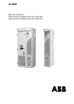
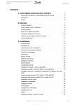
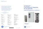
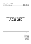
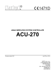
1
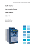
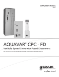
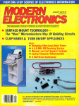
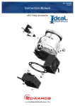
ACS 600 Hardware Manual Supplement ACS 601/604/607 AC Drives US Supplement ACS 601/604/607 US Supplement Hardware Manual Supplement ACS600-US-04S 3AUA489002B5071 R0101 REV C EFFECTIVE: 11/12/2001 SUPERSEDES: 12/15/98 2001 ABB Inc. All Rights Reserved. Table of Contents Safety Instructions . . . . . . . . . . . . . . . . . . . . . . . . . . . . . . . . . . . . . . . . . . . . . . . . . . . . . . . iii Warnings and Notes . . . . . . . . . . . . . . . . . . . . . . . . . . . . . . . . . . . . . . . . . . . . . . . . . . . iii Warnings . . . . . . . . . . . . . . . . . . . . . . . . . . . . . . . . . . . . . . . . . . . . . . . . . . . . . . . . . iii Notes. . . . . . . . . . . . . . . . . . . . . . . . . . . . . . . . . . . . . . . . . . . . . . . . . . . . . . . . . . . . iii Supply Connections. . . . . . . . . . . . . . . . . . . . . . . . . . . . . . . . . . . . . . . . . . . . . . . . . . . . v Ground Fault Protective Function . . . . . . . . . . . . . . . . . . . . . . . . . . . . . . . . . . . . . . . . . vi Emergency Stop Devices . . . . . . . . . . . . . . . . . . . . . . . . . . . . . . . . . . . . . . . . . . . . . . . vi Ground Connections . . . . . . . . . . . . . . . . . . . . . . . . . . . . . . . . . . . . . . . . . . . . . . . . . . . vi Motor Connections. . . . . . . . . . . . . . . . . . . . . . . . . . . . . . . . . . . . . . . . . . . . . . . . . . . . vii Conduit . . . . . . . . . . . . . . . . . . . . . . . . . . . . . . . . . . . . . . . . . . . . . . . . . . . . . . . . . . . . vii Armored Cable. . . . . . . . . . . . . . . . . . . . . . . . . . . . . . . . . . . . . . . . . . . . . . . . . . . . . . . vii Motor Insulation Requirements . . . . . . . . . . . . . . . . . . . . . . . . . . . . . . . . . . . . . . . vii Power Factor Correction Capacitors . . . . . . . . . . . . . . . . . . . . . . . . . . . . . . . . . . . . ix Output Contactors . . . . . . . . . . . . . . . . . . . . . . . . . . . . . . . . . . . . . . . . . . . . . . . . . . x EMC . . . . . . . . . . . . . . . . . . . . . . . . . . . . . . . . . . . . . . . . . . . . . . . . . . . . . . . . . . . . x Mechanical Installation . . . . . . . . . . . . . . . . . . . . . . . . . . . . . . . . . . . . . . . . . . . . . . x Chapter 1 – Introduction . . . . . . . . . . . . . . . . . . . . . . . . . . . . . . . . . . . . . . . . . . . . . . . . . 1-1 Overview . . . . . . . . . . . . . . . . . . . . . . . . . . . . . . . . . . . . . . . . . . . . . . . . . . . . . . . . . . Intended Audience. . . . . . . . . . . . . . . . . . . . . . . . . . . . . . . . . . . . . . . . . . . . . . . . . . . What this Manual Contains . . . . . . . . . . . . . . . . . . . . . . . . . . . . . . . . . . . . . . . . . . . . Related Publications . . . . . . . . . . . . . . . . . . . . . . . . . . . . . . . . . . . . . . . . . . . . . . . . . Product Family. . . . . . . . . . . . . . . . . . . . . . . . . . . . . . . . . . . . . . . . . . . . . . . . . . . . . . Delivery Check. . . . . . . . . . . . . . . . . . . . . . . . . . . . . . . . . . . . . . . . . . . . . . . . . . . . . . Nameplate . . . . . . . . . . . . . . . . . . . . . . . . . . . . . . . . . . . . . . . . . . . . . . . . . . . . . . Type Code. . . . . . . . . . . . . . . . . . . . . . . . . . . . . . . . . . . . . . . . . . . . . . . . . . . . . . Frame Size . . . . . . . . . . . . . . . . . . . . . . . . . . . . . . . . . . . . . . . . . . . . . . . . . . . . . ACx 600 Type Code . . . . . . . . . . . . . . . . . . . . . . . . . . . . . . . . . . . . . . . . . . . . . . . . . Inquiries . . . . . . . . . . . . . . . . . . . . . . . . . . . . . . . . . . . . . . . . . . . . . . . . . . . . . . . . . . . 1-1 1-1 1-1 1-2 1-2 1-2 1-2 1-2 1-2 1-3 1-4 Appendix A – ACS/ACC 600 Technical Data . . . . . . . . . . . . . . . . . . . . . . . . . . . . . . . . .A-1 Drive Output Ratings . . . . . . . . . . . . . . . . . . . . . . . . . . . . . . . . . . . . . . . . . . . . . . . . . A-1 Output Current Derating For High Ambient Temperature . . . . . . . . . . . . . . . . . . A-3 Diagram. . . . . . . . . . . . . . . . . . . . . . . . . . . . . . . . . . . . . . . . . . . . . . . . . . . . . . . . A-5 Output Current Derating For High Altitude . . . . . . . . . . . . . . . . . . . . . . . . . . . . . A-6 Temperature Derating For High Altitude . . . . . . . . . . . . . . . . . . . . . . . . . . . . . . . A-7 Fuses . . . . . . . . . . . . . . . . . . . . . . . . . . . . . . . . . . . . . . . . . . . . . . . . . . . . . . . . . . . . . A-8 Cable Entries . . . . . . . . . . . . . . . . . . . . . . . . . . . . . . . . . . . . . . . . . . . . . . . . . . . . . . . A-9 External Control Connections (NIOC) . . . . . . . . . . . . . . . . . . . . . . . . . . . . . . . . . . . A-11 Heat DIssipation Requirements. . . . . . . . . . . . . . . . . . . . . . . . . . . . . . . . . . . . . A-12 601/604/607 US Supplement i Cooling Air Flow Requirements . . . . . . . . . . . . . . . . . . . . . . . . . . . . . . . . . . . . . . . . Dimensions and Weights . . . . . . . . . . . . . . . . . . . . . . . . . . . . . . . . . . . . . . . . . . . . Input Power Connection . . . . . . . . . . . . . . . . . . . . . . . . . . . . . . . . . . . . . . . . . . . . . Motor Connection . . . . . . . . . . . . . . . . . . . . . . . . . . . . . . . . . . . . . . . . . . . . . . . . . . Efficiency and Cooling . . . . . . . . . . . . . . . . . . . . . . . . . . . . . . . . . . . . . . . . . . . . . . . External Control Connections . . . . . . . . . . . . . . . . . . . . . . . . . . . . . . . . . . . . . . . . . Encoder Signals . . . . . . . . . . . . . . . . . . . . . . . . . . . . . . . . . . . . . . . . . . . . . . . . Application Program . . . . . . . . . . . . . . . . . . . . . . . . . . . . . . . . . . . . . . . . . . . . . . . . Application Macros . . . . . . . . . . . . . . . . . . . . . . . . . . . . . . . . . . . . . . . . . . . . . . Protection Features . . . . . . . . . . . . . . . . . . . . . . . . . . . . . . . . . . . . . . . . . . . . . . Equipment Warranty and Liability . . . . . . . . . . . . . . . . . . . . . . . . . . . . . . . . . . . . . . Limitation of Liability . . . . . . . . . . . . . . . . . . . . . . . . . . . . . . . . . . . . . . . . . . . . . A-13 A-14 A-15 A-15 A-15 A-16 A-18 A-19 A-19 A-20 A-21 A-21 Appendix B – ACS/ACC 600 US Only Drawings . . . . . . . . . . . . . . . . . . . . . . . . . . . . . .B-1 601/604/607 US Supplement ii Safety Instructions Overview This chapter states the safety instructions which must be followed when installing, operating and servicing the ACx 600. If neglected, physical injury and death may follow, or damage may occur to the AC drive, the motor and driven equipment. The material in this chapter must be studied before attempting any work on, or with, the unit. Warnings and Notes This manual distinguishes two sorts of safety instructions. Warnings are used to inform of conditions which can, if proper steps are not taken, lead to a serious fault condition, physical injury or death. Notes are used when the reader is required to pay special attention or when there is additional information available on the subject. Notes are less crucial than Warnings, but should not be disregarded. Warnings Warnings are provided in the instruction manuals and on labels attached to the AC drive. Readers are informed of situations that can result in serious physical injury and/or serious damage to equipment with the following symbols: Dangerous Voltage Warning: warns of situations in which a high voltage can cause physical injury and/or damage equipment. The text next to this symbol describes ways to avoid the danger. General Warning: warns of situations which can cause physical injury and/or damage equipment by means other than electrical. The text next to this symbol describes ways to avoid the danger. Electrostatic Discharge Warning: warns of situations in which an electrostatic discharge can damage equipment. The text next to this symbol describes ways to avoid the danger. Notes Notes are provided in the instruction manuals to notify readers of the need for special attention or additional information available on the subject with the following symbols: CAUTION! Note: 601/604/607 US Supplement Caution aims to draw special attention to a particular issue. Note gives additional information or points out more information available on the subject. iii Safety Instructions Installation and Maintenance Safety These safety instructions are intended for all work on the ACx 600. In addition to the instructions given below, there are more safety instructions on the first pages of the appropriate hardware manual. WARNING! All electrical installation and maintenance work on the ACx 600 should be carried out by qualified electricians. The ACx 600 and adjoining equipment must be properly grounded. Do not attempt any work on a powered ACx 600. After switching off the power, always allow the intermediate circuit capacitors 5 minutes to discharge before working on the drive, the motor or the motor cable. It is good practice to check (with a voltage indicating instrument) that the drive is in fact discharged before beginning work. The ACx 600 motor cable terminals are at a dangerously high voltage when power is applied, regardless of motor operation. The brake control terminals (UDC+, UDC-, R+ and R- terminals) carry a dangerous DC voltage (over 500V). There can be dangerous voltages inside the ACx 600 from external control circuits when the ACx 600 input power is shut off. Exercise appropriate care when working with the unit. Neglecting these instructions can cause physical injury and death. WARNING! The ACx 600 introduces electric motors, drive train mechanisms and driven machines to an extended operating range. The ACx 600 can be adjusted to operate the motor at speeds above and below the speed provided by connecting the motor directly to the power line. Before adjusting the drive and putting it into service, make sure that the motor and all driven equipment is suitable for operation throughout the speed range provided by the AC drive. WARNING! If an external source for start command is selected and it is ON, the ACx 600 will start immediately after fault reset unless the drive is configured for 3-wire Start/Stop. WARNING! When the control location is not set to Local (L not shown in the status line of the display), the Stop key on the Control Panel will not stop the drive. To stop the drive using the Control Panel you must press the LOC/REM key and then the Stop key . WARNING! The printed circuit boards contain integrated circuits that are extremely sensitive to electrostatic discharge. Exercise appropriate care when working on the unit to avoid permanent damage to the circuits. Do not touch the boards unnecessarily. iv 601/604/607 US Supplement Safety Instructions WARNING! There are several automatic reset functions in the ACx 600. If selected, they reset the unit and resume operation after a fault. These functions should not be selected if other equipment is not compatible with this kind of operation, or dangerous situations can be caused by such action. Supply Connections The ACx 601 does not include a disconnecting means. An input power disconnecting means must be installed between the AC power source and the ACx 601. The disconnecting means must conform to the applicable safety regulations. The disconnecting means must be locked in the open position during installation and maintenance work. The motor must not be controlled with the supply disconnecting means; instead, the and keys of the Control Panel or commands via the I/O board of the ACx 600 should be used. The maximum number of charging cycles of the d.c. capacitors of ACx 600 (i.e. power-ups by applying power) is five in ten minutes. ACx 6x7 units include an on-load isolating fused disconnect with a through the door handle. This switch does not switch off power from the EMC Line filter of the ACx 607-0490-3/5/6, -0610-3/5/6 and -07605/6 units. For ACx6x7-0490-3/5/6, -0610-3/5/6, and -0760-5/6 units with EMC filters and for the ACx 604 module, a supply disconnecting device must be installed in the supply, by which the electrical parts of the unit can be separated from the power network during installation and maintenance work. The supply disconnecting device must be locked to the open position during installation and maintenance work. WARNING! Never connect the line power to the ACx 600 output terminals U2, V2, or W2. If frequent bypassing is required, mechanically interlocked switches or contactors should be employed. Line voltage applied to the output may result in permanent damage to the unit. Operation outside the nominal input line voltage range should not be attempted, as overvoltages can result in permanent damage to the ACx 600. If an ACx 601 with the integrated EMC filter (code 0 in the type code for EMC Filters) is connected to an ungrounded power system or high resistance grounded power system (over 30 Ohms), the power line will be connected to ground potential through the EMC filter capacitors of the ACx 601. This may cause danger or damage the unit. Disconnect the EMC filter capacitors before connecting the ACx 601 to an ungrounded power system. For detailed instructions on how to do this, please contact your local ABB distributor. It is not allowed to install an ACx6x4/6x7 with EMC filter options to 601/604/607 US Supplement v Safety Instructions ungrounded systems, or high resistance grounded power systems (over 30 ohms). The main power will be connected to earth potential through the EMC filter of the ACx 600 which may cause danger or damage to the unit. Disconnect the EMC filter capacitors before connecting the ACx 600 to ungrounded systems. For detailed instructions on how to do this, please contact your local ABB distributor. Ground Fault Protective Function The ACx 600 is equipped with an internal ground fault protective function to protect the unit against ground faults in the drive, the motor and the motor cable. This is not a personal safety or a fire protection feature. The ground fault protective function of the ACx 600 can be set to warning only by Parameter 30.17 for Standard Application Program and Parameter 30.11 for Crane Application Program. The internal ground (earth) fault protection is not in use in the 12-pulse supplied units. For ACX 62x units, refer to the ACx 607 hardware manual subsection labelled “Special ACx 6x7 units from 315 to 630 kW”. The EMC filter of the ACx 600 includes capacitors connected between the power circuit and the chassis. These capacitors increase the ground leakage current from the AC line through the ground (PE) connection and may cause some ground fault current circuit breakers to trip. Emergency Stop Devices The person responsible for the overall design and operation of the driven process must make sure that the installation includes emergency stop devices and any other safety equipment that may be needed. Pressing the STOP key on the Control Panel of ACx 600 does not generate an emergency stop of the motor or separate the drive from dangerous potential. A Line Contactor with provisions for a remote power cut-off switch is available as a factory installed option for the ACx 607. Cutting off power to the drive allows the motor to coast to a stop. Ground Connections The ACx 600 and adjoining equipment must be properly grounded. The ACx 600 and the motor must be grounded at the installation site to ensure personnel safety in all circumstances and in addition to reduce electromagnetic emission and pick-up. Make sure that grounding conductors are adequately sized as required by safety regulations. In CE compliant installations and in other installations where EMC emissions must be minimized, 360 degree high frequency grounding of cable entries is done in order to suppress electromagnetic disturbances. In addition, power cable shields must be connected to the ground (PE) in order to meet safety regulations. Power cable shields are suitable for use as equipment grounding conductors only when the shield conductors are adequately sized as required by safety regulations. vi 601/604/607 US Supplement Safety Instructions The ACx 600 ground terminals should not be connected in series in case of a multiple installation. Incorrect grounding can cause physical injury, death or equipment malfunction and increase electromagnetic interference. Motor Connections WARNING! Operation is not allowed if the motor nominal voltage is less than one half of the ACx 600 nominal input voltage, or the motor nominal current is less than 1/6 of the ACx 600 nominal output current. WARNING! Do not make any voltage tolerance or insulation resistance test (Hi-Pot or Megger) on any part of the ACx 600. Disconnect motor wires before making any tests of the motor or the cables between the drive and motor. Conduit Metallic conduit must be used for motor wiring unless armored cable or power shield cable is used. Where conduits must be coupled together, the joint must be bridged with a ground conductor bonded to the conduit on each side of the joint. The conduits must also be bonded to the drive enclosure. Use separate conduits for input power, motor, brake resistors, and control wiring. Do not run motor wiring from more than one drive in the same conduit. Armored Cable If metallic conduit is not used, type MC continuous corrugated aluminum armor cable with symmetrical grounds or power shield cable must be used for the motor cables. If these cables are used, the motor cables can be run in the same cable tray as other 460V or 600V power wiring. Control and signal cables must not be run in the same tray as power cables. Six conductor (3 phases and 3 ground) type MC continuous corrugated aluminum armor cable with symmetrical grounds is available from the following suppliers. Trade names are in parentheses. Anixter Wire & Cable (Philsheath) BICC General Corp (Philsheath) Rockbestos Co. (Gardex) Oaknite (CLX) Power shielded cables are available from Belded, Olflex, and Pirelli. Motor Insulation Requirements 601/604/607 US Supplement As with all AC drives employing the most modern IGBT invertor technology, the output waveform of the ACx 600 consists of a series of rectangular voltage pulses. Regardless of the output frequency, the voltage of the pulses is approximately 1.35 times the input line voltage with a very short rise time. vii Safety Instructions The voltage of the pulses can be almost double at the motor terminals, depending on the length of cable between the drive and the motor. This in turn can cause additional stress to the motor insulation. The motor manufacturer should be consulted regarding the characteristics of the motor insulation system. Failure of the motor to fulfill the following requirements may shorten its life. The following table lists the insulation requirements for motors used with ACx 600 AC drives. Motor Type Nominal AC Line Voltage Motor Insulation Requirement ABB Motors (manufactured from beginning of 1998) VN < 500 V Standard insulation system 525 V < VN ≤690 V Standard insulation and dv/dt filter or special insulation system Random-wound Motors VN ≤420 V Motor insulation system must withstand VPK = 1300 V. 420 V < VN ≤500 V If motor insulation system withstands VPK = 1600 V and 0.2 µs rise time, a dv/dt filter is not needed. With a dv/dt filter at the output of the ACx 600, motor insulation system must withstand VPK = 1300 V. Form-wound Motors 500 V < VN ≤600 V Motor insulation system must withstand VPK = 1600 V. A dv/dt filter must be used at the output of the ACx 600. 600 V < VN ≤690 V Motor insulation system must withstand VPK = 1800 V. A dv/dt filter must be used at the output of the ACx 600. VN ≤690 V If motor insulation system withstands VPK = 2000 V and rise time 0.3 µs, no dv/dt filter is needed. Symbol Definition VN nominal power line voltage VPK peak line to line voltage at motor terminals Rise time: Rise time is line to line voltage change rate at motor terminals (the interval during which the voltage changes from 10% to 90% of the whole voltage range) t viii = 0.8 · VPK/(dv/dt) VPK and t depend on cable length. Read the values of VPK and dv/dt from the diagrams below. 601/604/607 US Supplement Safety Instructions Without Filter Below is a diagram of VPK and dv/dt as a function of cable length when no dv/dt filter is used. 5 4 ,5 4 3 ,5 VPK / VN 3 2 ,5 2 1 ,5 dv/dt / (kV/µs) 1 0 ,5 0 0 50 1 00 0 1 50 2 00 2 50 500 3 00 (m) 1000 (feet) Cable length With dv/dt Filter Below is a diagram of VPK and dv/dt as a function of cable length with dv/dt filter at the output of the ACx 600. 5 4,5 4 3,5 3 2,5 VPK / VN 2 1,5 1 dv/dt / (kV/µs) 0,5 0 0 0 50 100 150 500 200 250 300 (m) 1000 (feet) Cable length Power Factor Correction Capacitors 601/604/607 US Supplement Power factor correction capacitors and surge absorbers must not be connected between the drive and the motor. These devices are not designed to be used with AC drives, and will degrade motor control accuracy. They can cause permanent damage to the ACx 600 or themselves due to the rapid changes in the ACx 600 output voltage. ix Safety Instructions Power factor correction capacitors in parallel with the ACx 600 three phase input can be problematic. Contact factory if questions arise. Output Contactors If a contactor is used between the output of the ACx 600 and the motor with DTC control mode selected, the output voltage of the ACx 600 must be controlled to zero before the contactor is opened: ACx 600 units via parameter 21.3, choose COAST. If RAMP is selected, the output of the ACx 600 must be reduced to zero using Parameter 16.1 by giving zero V DC to the selected digital input. Otherwise the contactor will be damaged. In scalar control the contactor can be opened with ACx/ACC 600 running. Varistors or RC networks (AC) or diodes (DC) should be used to protect against voltage transients generated by contactor coils. The protective components should be mounted as close as possible to the contactor coils. Protective components should not be installed at the NIOC board terminal block. EMC When used with inductive loads (relays, contactors, motors), the relay contacts of ACx 600 must be protected with varistors or RC networks (AC) or diodes (DC) against voltage transients. The protective components should not be installed at the NIOC board terminal block. Installing control devices (contactors or relays) or control cables other than those of the ACx 600 inside the drive enclosure is not acceptable. Note: If safety switches, contactors, connection boxes or similar equipment are installed between the drive and the motor, they should be installed in a metal enclosure in a way that the conduit or motor cable shielding runs consistently without breaks from the drive to the motor, so the emission level will be minimized. Mechanical Installation CAUTION! The ACx 601 weighs a considerable amount, and should not be handled by the front cover. The unit should only be placed on its back. Exercise appropriate care when maneuvering the unit to avoid damage and injury. Lifting the ACx 601 is much easier and safer with two people working together. CAUTION! The ACx 6x7 should only be transported on the original pallet, or with a proper lifting device using the lifting lugs on top of the cabinet. The drive is not intended to be lifted by running lines under the unit. The ACx 607 center of gravity is quite high, and there is a risk of over turning the unit. The ACx 607 can be laid on it’s back to fit though confined spaces. Exercise appropriate care when maneuvering the unit to avoid damage or injury. CAUTION! Make sure that dust from drilling does not enter the ACx 600 when installing. Electrically conductive dust inside the unit may cause damage or lead to malfunction. x 601/604/607 US Supplement Safety Instructions CAUTION! Do not fasten the ACx 600 by riveting or welding. WARNING! The cooling air flows and space requirements must be fulfilled. Special attention must be paid to cooling if units are installed in confined spaces and user defined cabinets. 601/604/607 US Supplement xi Safety Instructions xii 601/604/607 US Supplement Chapter 1 – Introduction Overview This chapter describes the purpose and contents of this manual. This manual is a supplement to the ACx 601/604/607 AC Drive Hardware Manuals. The information contained in this manual is: • specific to 200 to 240 VAC product as well as 380-500 V product distinguished by digit 11 in the ACS 600 type code being designated as a 4. The information in the manual takes precedent over any contradictory data found in any other user manual. • for installations within the United States that must be installed per the National Electric Code and local codes. Intended Audience The intended audience of this manual are people who are responsible for installing, starting and servicing the ACx 601 or ACx 604/607 AC drive. The audience is expected to: • Have a basic knowledge of physical and electrical fundamentals, electrical wiring practices, electrical components and electrical schematic symbols. • Have no prior experience of ABB products. • Have no prior experience of AC drives. • Have no prior experience of the ACx 600 product family. • Have no prior experience or training of installing, commissioning, operating and servicing the ACx 600. What this Manual Contains Safety Instructions are placed on the first pages of this manual. The safety instructions describe the formats for various warnings and notations in use in this manual. The chapter also states the general safety instructions that are intended for all work on the ACx 600. Chapter 1 - Introduction gives information on the related publications, product family, delivery check, and type code of the ACx 601 or ACx 604/607. Chapter 1 in this manual supersedes the entire Chapter 1 in the ACx 601 and ACx 604/607 AC Drive Hardware Manuals. Appendix A - ACx 604/607 Technical Data lists the ACx 600 technical specifications. Appendix A in this manual supersedes the entire Appendix A in the ACx 601 and ACx 604/607 AC Drive Hardware Manuals. Refer only to the Appendix A in this manual and disregard the Appendix A in the Hardware Manuals. 601/604/607 US Supplement 1-1 Chapter 1 – Introduction Related Publications In addition to this manual the ACx 601/604/607 AC drive user documentation includes the following publications: • ACx 601 or ACx 604/607 Hardware Manual • ACx 600 Firmware Manual • ACx 600 DriveWindow User’s Manual (optional) • Several Option Module Manuals • ACx 600 Technical Catalog • ACx 600 Converter Module Installation In User Defined Cabinet Product Family The ACx 600 product family of three phase AC drives includes • the ACx 600 (for most applications) • the ACC 600 (for crane drive applications) • the ACx 600 MultiDrive (for multi drive applications) The application programs are introduced in Appendix – A. Study this manual carefully before installing, commissioning, operating or servicing the drive. We expect that you have a basic knowledge of physical and electrical fundamentals, electrical wiring practices, electrical components and electrical schematic symbols. Delivery Check 1-2 Check that there are no signs of damage. Before attempting installation and operation, check the information on the drive nameplate to verify that the unit is the correct model. Nameplate Each ACx 600 has a nameplate for identification purposes. See Figure 1-1. The nameplate data includes a type code and a serial number which allow individual recognition of each unit. Type Code The ACx 600 Type Code contains information on the properties and configuration of the drive. The Type Code Chart explains the significance of each digit or character in the Type Code. Frame Size ACx 600 drives are manufactured in several different chassis sizes that are designated as Frame R2, R3, etc. Drives of several different ratings are manufactured in the same frame. The ACx 600 rating tables on page A-1 in Appendix A list the Frame Size used for each Type Code. The Frame Size is not marked on the nameplate. 601/604/607 US Supplement Chapter 1 – Introduction U1 3-380...500V U2 3-0...U1 I1n/I1nsq 168/198A I2n/I2nsq 164/193A f1 48...63Hz f2 0...300Hz ACS60101405... U1 3-380...480V U2 3-0...U1 I1hd/I1n 143/184A I2hd/I2n 141/180A f1 57...63Hz f2 0...300Hz ACS60101404... IEC Ratings CE Marking FIIND Type Code ABB Industry Oy Serno *1983509999* 000C150001 NEMA Ratings UL, cUL & CSA Markings USINY Type Code Serial Number Bar Code Type Code continued Figure 1-1. ACx 600 Nameplate ACx 600 Type Code The meaning of main selections of ACx 600 type code characters is given in the table below. Not all selections are available for all types. More information on selections is available in the ACx 600 price list. Character Meaning no. Example: ACx60701003000B1200901 1 Product Category A = AC Drive 2...3 Product Type CS = Standard, CC = Crane Drive 4 Product Family 6 = ACx 600 5 Input Bridge 0 = 6-pulse rectifier, 1 = Regenerative 4Q IGBT Bridge, 2 = 12-pulse rectifier, 7 = Regenerative 4Q thyristor bridge 6 Construction 1 = Wall mounted, 4 = Module, 7 = Drives-MNS Cabinet 7...10 Power Rating (kVA) 11 12...14 15 16 601/604/607 US Supplement Voltage Rating 2 = 240 VAC 3 = 380/400/415 VAC 4 = 380/400/415/440/460/480/500 VAC 5 = 380/400/415/440/460/480/500 VAC 6 = 525/550/575/600/660/690 VAC Option 1, Option 2, Option 3 Application Software x = Languages and Application Macro Options Refer to Appendix A: Ratings Appendix A: Application Programs Control Panel 0 = None, 1 = CDP 312 Control Panel included, 4 = Customer I/O Terminal Block X2, 5 = Options 1 + 4 1-3 Chapter 1 – Introduction Character Meaning no. 17 Degree of Protection 0 = IP 00 (chassis), A = IP 21, 2 = IP 22, 5 = IP 54, 6 = IP 00 with Coated Boards, 7 = IP 22 with Coated Boards, 8 = IP 42 with Coated Boards 9 = IP 54 with Coated Boards B = IP 21 with Coated Boards 18 Line Input and Protection Options 19 Starter for Auxiliary Motor Fan 20 Filters 0 = CE with EMC Filters (not for 690V or 12-pulse rectifier) 230V Not CE 3 = CE with output dv/dt Filters + EMC Filters (not for 690V) 5 = Output dv/dt Filters + no EMC Filters 8 = US Standard, US conduit: No CE, no EMC filters, 9 = CE Low Voltage and Machinery Directives; No EMC (ACx 607 only, secondary of all transformers 220 VAC) (Not valid for XTs with “4” top/top “6” top/ top w/brake chopper.) A = 8 + dv/dt Filter 21 Braking Chopper and Cabling Direction 0 = No Brake Chopper - Bottom Entry / Bottom Exit 1 = Brake Chopper (Bottom Entry / Bottom Exit) 3 = Input Power Top Entry / Output Power Bottom Exit No brake chopper 4 = Input / Output Power Top Entry / Exit - No brake chopper (Not valid for XTs with dv/dt filters, EMC filters, or 12 pulse rectifier.) 5 = Option 1 and 3 6 = Option 1 and 4 (Not valid for XTs with dv/dt filters, EMC filters, or 12 pulse rectifier.) R = NDCU-XX 22 Other Options 0 = None, 1 = Version 5.x Software, 2 = Version 5.x Harmonized (ACx 6x7 only), 3 = Version 6.x Software Inquiries 1-4 Refer to Appendix A: Enclosures Appendix A: CE marking Any inquiries about the product should be addressed to the local distributor or ABB representative, quoting the type code and the serial number of the unit. If the local ABB representative cannot be contacted, inquiries should be directed to the address and phone numbers on the back cover of this manual. 601/604/607 US Supplement Appendix A – ACS/ACC 600 Technical Data Below are the Nema ratings for ACS/ACC 600 drives with nominal 240 and 460 volt 50 Hz and 60 Hz supplies. ACx = ACS/ACC. Symbols are described in the following the table. Drive Output Ratings Normal Use ACx 600 Type Code Duty Cycle 1/10 min I2N I2Nmax Duty Cycle 1/10 min SN PN PN 9/10min 1/10min [A] [A] Heavy-duty Use Duty Cycle 1) 2/15 s I2hd I2hdmax I2hd I2hdmax Shd 9/10min 1/10min 13/15s [kVA] [kW] [HP] [A] [A] [A] Phd Phd [kW] [HP] Frame Size 2/15s [A] [kVA] Three-phase supply ACx 601-0003-2 ACx 601-0005-2 ACx 601-0006-2 ACx 601-0009-2 ACx 601-0011-2 ACx 601-0016-2 ACx 601-0020-2 ACx 601-0025-2 ACx 601-0030-2 ACx 601-0040-2 ACx 601-0050-2 ACx 601-0060-2 ACx 601-0070-2 ACx 601-0080-2 ACx 601-0100-2 ACx 604/7-0120-2 ACx 604/7-0140-2 ACx 604/7-0170-2 voltage 200 - 240 V 7.8 8.6 3 11 12.1 5 15 16.5 6 18 19.8 9 25 28 11 32 35 16 48 53 20 60 66 25 75 83 30 88 97 40 114 125 50 143 157 60 178 187 70 211 232 80 248 300 100 316 348 120 395 435 150 480 528 200 1.1 1.5 2.2 3.7 5.5 7.5 11 15 18.5 22 30 37 45 55 75 90 110 150 1.5 2 3 5 7.5 10 15 20 25 30 40 50 60 75 100 125 150 200 5 7.8 11 15 18 25 32 48 60 75 88 114 143 178 192 273 316 395 7.5 11.7 17 23 27 38 48 72 90 113 132 171 215 255 317 390 474 593 5 7.8 11 15 18 25 32 48 60 75 88 114 143 178 211 273 316 395 10 2 15.6 3 22 5 30 6 36 9 50 11 64 16 96 20 120 25 150 30 176 40 228 50 286 60 340 70 422 80 520 100 632 120 790 150 0.8 1 1.1 1.5 1.5 2 2.2 3 3.7 5 5.5 7.5 7.5 10 11 15 15 20 18.5 25 22 30 30 40 37 50 45 60 55 75 75 100 90 125 110 150 Three-phase supply ACx 601-0006-4 ACx 601-0009-4 ACx 601-0011-4 ACx 601-0016-4 ACx 601-0020-4 ACx 601-0025-4 ACx 601-0030-4 ACx 601-0040-4 ACx 601-0050-4 ACx 601-0060-4 ACx 601-0070-4 ACx 601-0100-4 ACx 601-0120-4 ACx 601-0140-4 ACx 604/7-0120-4 ACx 604/7-0140-4 ACx 604/7-0170-4 ACx 604/7-0210-4 ACx 604/7-0260-4 voltage 380 - 500 V 7.6 8.4 6 11 12 7.5 15 17 10 21 23 16 27 30 20 34 37 25 41 45 30 52 57 40 65 72 50 77 85 60 96 106 70 124 136 100 156 172 120 180 198 140 156 172 120 180 198 140 216 238 170 260 286 210 316 348 260 414 455 320 4 5.5 7.5 11 15 18.5 22 30 37 45 55 75 90 110 90 110 132 160 200 250 5 7.5 10 15 20 25 30 40 50 60 75 100 125 150 125 150 150 200 250 300/ 350 400 500 600 700 6.2 7.6 11 15 19 24 31 41 47 58 68 86 113 141 113 141 172 200 240 300 9.3 11 17 23 27 36 47 62 71 87 98 126 168 203 168 203 246 300 360 450 6.2 7.6 11 15 19 24 31 41 47 58 68 86 113 141 113 141 172 200 240 300 12.4 15.2 22 30 36 48 62 82 94 116 130 168 224 270 224 270 328 400 480 600 5 6 9 11 16 20 25 30 40 50 60 70 100 120 100 120 140 170 210 260 3 4 5.5 7.5 11 15 18.5 22 30 37 45 55 75 90 75 90 110 132 160 200 3 5 7.5 10 10 15 20 30 30 40 50 60 75 100 75 100 125 150 200 250 R2 R2 R2 R3 R3 R4 R4 R5 R5 R5 R6 R6 R7 R7 R7 R7 R8 R8 R8 R9 365 456 570 694 548 684 855 1041 365 456 570 694 730 912 1140 1388 320 400 490 610 250 315 400 500 300 400 500 600 R9 2xR8 2xR9 2xR9 ACx 604/7-0320-4 ACx 604/7-0400-4 ACx 604/7-0490-5 ACx 604/7-0610-5 ACx 604/7-0760-5 480 570 694 874 601/604/607 US Supplement 528 627 764 961 400 490 610 760 315 400 500 630 R2 R3 R4 R5 R6 R7 R8 R9 A-1 Appendix A – ACS/ACC 600 Technical Data Current ratings are for operation up to 1000m (3300 ft) altitude and 40°C(104°F) ambient temperature (35° C/95°F for models ACx 601-0025-2, ACx 601-0050-2 and ACx 6010070-2 in IP54 enclosures). For high temperature and altitude derating, see pages A-3 to A-7. Note 1: The maximum allowed motor shaft power is limited to 1.5 · P hd. If the limit is exceeded, the motor torque and the I hdmax 2 s current is automatically restricted. The function protects the input bridge of the ACx 600 against overload. The current ratings are the same regardless of the supply voltage within one voltage range. The rated current of the ACx 60x must be higher than or equal to the rated motor current to achieve the rated motor power given in the table. Note 2: The load capacity (current and power) decreases if the installation site altitude exceeds 1000 meters (3300 ft.), or if the ambient temperature exceeds 40 °C. A-2 Usually dv/dt filters are not needed at the output of 240 V units. 601/604/607 US Supplement Appendix A – ACS/ACC 600 Technical Data Symbols Used in Rating Table Normal use (10% overload capacity): I2N rated RMS output current I2Nmax short term rms overload current (allowed for one minute every 10 minutes). SN PN rated apparent output power typical motor power. The power ratings in kW apply to most IEC 34 motors. The power ratings in HP apply to most four pole NEMA rated motors. Heavy-duty use (50% or 100% overload capacity): I2hd rated RMS output current I2hdmax rms overload current (allowed for one minute every 10 minutes or 2 seconds every 15 seconds) Maximum current depends on parameter setting, refer to Firmware Manual. Shd rated apparent output power Phd typical motor power. The power ratings in kW apply to most IEC 34 motors. The power ratings in HP apply to most four pole NEMA rated motors. Output Current Derating For High Ambient Temperature When the ambient temperature of the air around the drive exceeds the rated temperature, the rated output current is decreased by some percentage of the normal current rating for every degree above the rated temperature. The output current is calculated by multiplying the I2N current given in the rating table by a derating factor determined from the derating curves. The derating factor is determined by the ambient temperature, the type of enclosure and the duty classification. ACx 601 Drives Note:Curve numbers refer to the Derate Curves and the Derate Table which immediately follow the derating instructions. Maximum temperature in all cases should not exceed 50 ° C. For IP 21/22 enclosures with Normal Use: Below +40 ° C: Apply curve 1 (no derate) to I2N for all drives except model ACx 601-0100-2 which requires application of curve 2. Above +40 ° C: Decrease I2N by 3.5% for every 1 ° C above 40 ° C. Reduction should begin from the value applicable at 40 ° C (i.e., 92% of I2N for ACx 601-0100-2, 100% for all other drives). For IP 21/22 enclosures with Heavy Duty Use: Below +40 ° C: Use the I2HD current rating given in the Drive Output Ratings table. No derating is required. Above +40 ° C: Calculate a tentative derated current per the IP 21/ 22 Normal Use, Above +40 ° C instructions above. Compare this calculated value with the I2HD current given in the Drive Output Ratings table. The current rating equals the smaller of I2HD from the Drive Output Ratings table or the calculated derated current. 601/604/607 US Supplement A-3 Appendix A – ACS/ACC 600 Technical Data For IP 54 enclosures with Normal Use: Below +40 ° C: Locate the pertinent drive type code in the Derate Table to determine the curve number to apply. Find the ambient temperature at the bottom of the Derate Curves. Follow this temperature up vertically to where it meets the applicable curve number. From the point of intersection read across horizontally to determine the appropriate percent derate. The current rating equals the I2N current from the Drive Output Ratings table times the percent derate. Above +40 ° C: Calculate the I2N current derate (if any) at 40 ° C per the IP 54 Normal Use, Below +40 ° C instructions immediately above. Starting from this current level decrease the current rating an additional 3.5% of I2N for each 1 ° C above 40 ° C. For IP 54 enclosures with Heavy Duty Use: Below +40 ° C: Use the I2HD current rating given in the Drive Output Ratings table. No derating is required. Above +40 ° C: Calculate a tentative derated current per the IP 54 Normal Use, Above +40 ° C instructions above. Compare this calculated value with the I2HD current given in the Drive Output Ratings table. The current rating equals the smaller of I2HD from the Drive Output Ratings table or the calculated derated current. ACx 607 Drives Maximum temperature in all cases should not exceed 50 ° C. For IP 21/22 enclosures with Normal Use: Below +40 ° C: Use the I2N current rating given in the Drive Output Ratings table. No derating is required. Above +40 ° C: Decrease I2N by 1.5% for every 1 ° C above 40 ° C. For IP 21/22 enclosures with Heavy Duty Use: Below +40 ° C: Use the I2HD current rating given in the Drive Output Ratings table. No derating is required. Above +40 ° C: Use the I2HD current rating given in the Drive Output Ratings table. No derating is required. For IP 54 enclosures with Normal Use: Below +40 ° C: Use the I2N current rating given in the Drive Output Ratings table. No derating is required. Above +40 ° C: Decrease I2N by 1.5% for every 1 ° C above 40 ° C. For IP 54 enclosures with Heavy Duty Use: Below +40 ° C: Use the I2HD current rating given in the Drive Output Ratings table. No derating is required. Above +40 ° C: Use the I2HD current rating given in the Drive A-4 601/604/607 US Supplement Appendix A – ACS/ACC 600 Technical Data Output Ratings table. No derating is required. Diagram Output current for ACS/ACC 601 with degree of protection IP 54 and with ambient temperature from 25 ° C (77 ° F) to 40 ° C (104 ° F) is presented in the diagram below. I2N total rms output current for normal use. Derate Curves 100 1 95 4 5 90 2 3 85 80 75 70 65 60 24 26 28 30 32 34 36 38 40 t( ° C) 75 79 82 86 90 93 97 100 104 t( ° F) Derate Table Curve 1 (100 % no derating) Curve 2 Curve 3 Curve 4 Curve 5 ACx 601-0020-4 ACx 601-0006-4 ACx 601-0009-4 ACx 601-0016-4 ACx 601-0011-4 ACx 601-0025-4 ACx 601-0100-2 ACx 601-0050-4 ACx 601-0100-4 ACx 601-0030-4 ACx 601-0025-2 ACx 601-0060-4 ACx 601-0040-4 ACx 601-0050-2 ACx 601-0070-4 ACx 601-0070-2 ACx 601-0003-2 ACx 601-0005-2 ACx 601-0006-2 ACx 601-0009-2 ACx 601-0011-2 ACx 601-0016-2 ACx 601-0020-2 ACx 601-0030-2 ACx 601-0040-2 ACx 601-0060-2 ACx 601-0080-2 601/604/607 US Supplement A-5 Appendix A – ACS/ACC 600 Technical Data Output Current Derating For High Altitude When the altitude of the installation site exceeds 1000 m (3300 ft.) above sea level, the rated output current for Normal Use is decreased by 1% for every additional 100 m (300 ft.). If the installation site is higher than 2000 m (6600 ft.) above sea level, please contact your local ABB distributor or office for further information. For Heavy Duty Use, apply the I2HD current given in the rating table up to 2000 m (6600 ft.). No derating is required. The output current is calculated by multiplying the I2N current given in the rating table by the derating factor determined from the derating curve. Output Current Derating Factors for High Altitude (Percent of I2N ) 100% 98% 96% 94% 92% 90% 88% 3300 1000 4900 1500 6600 Feet 2000 Meters Altitude A-6 601/604/607 US Supplement Appendix A – ACS/ACC 600 Technical Data Temperature Derating For High Altitude When the altitude of the installation site exceeds 1000 m (3300 ft.) above sea level, the rated ambient temperature can be decreased as an alternative to decreasing the rated output current. Use curve 2 for models ACx 601-0025-2, ACx 601-0050-2 and ACx 601-0070-2 when they are in IP54 enclosures. Ambient Temperature Derating for High Altitude 40 °C 39 °C 104 °F 1 102 °F 38 °C 100 °F 37 °C 98 °F 36 °C 96 °F 35 °C 34 °C 94 °F 2 92 °F 33 °C 90 °F 32 °C 88 °F 31 °C 30 °C 3300 1000 601/604/607 US Supplement 4900 1500 86 °F 6600 Ft 2000 M A-7 Appendix A – ACS/ACC 600 Technical Data Recommended input fuse ratings of the ACS/ACC 601 are below. A minimum rated current in amperes, A2s maximum clearing I2t value, V rated voltage in volts. Only ultra rapid fuses guarantee proper protection for the rectifier semiconductors. Fuses ACx 600 Type Code ACx 601-0003-2 ACx 601-0005-2 ACx 601-0006-4 ACx 601-0009-4 ACx 601-0006-2 ACx 601-0011-4 ACx 601-0009-2 ACx 601-0016-4 ACx 601-0011-2 ACx 601-0020-4 ACx 601-0016-2 ACx 601-0025-4 ACx 601-0030-4 ACx 601-0020-2 ACx 601-0040-4 ACx 601-0025-2 ACx-601-0030-2 ACx 601-0050-4 ACx 601-0060-4 ACx 601-0040-2 ACx 601-0050-2 ACx 601-0070-4 ACx 601-0100-4 ACx 601-0060-2 ACx 601-0070-2 ACx 601-0080-2 ACx 601-0100-2 ACx 601-0120-4 ACx 601-0140-4 ACx 604-0120-2 ACx 604-0140-2 ACx 604-0170-2 ACS607-0120-4 ACS607-0140-4 ACS607-0170-4 ACS607-0210-4 ACS607-0260-4 ACS607-0320-4 ACS607-0400-4 ACS607-0490-5 ACS607-0610-5 ACS607-0760-5 Fuses A Clearing A2s V Manufacturer Type DIN 43653 Size 16 48 660 Bussmann 170M1359 000/80 16 16 25 25 32 32 40 40 50 50 63 80 80 125 48 48 130 130 270 270 460 460 770 770 1450 1250 2550 3700 660 660 660 660 660 660 660 660 660 660 660 660 660 660 Bussmann Bussmann Bussmann Bussmann Bussmann Bussmann Bussmann Bussmann Bussmann Bussmann Bussmann Bussmann Bussmann Bussmann 170M1359 170M1359 170M1361 170M1361 170M1362 170M1362 170M1363 170M1363 170M1364 170M1364 170M1365 170M3011 170M1366 170M3013 000/80 000/80 000/80 000/80 000/80 000/80 000/80 000/80 000/80 000/80 000/80 1/80 000/80 1/80 660 660 660 660 660 660 660 Bussmann Bussmann Bussmann Bussmann Bussmann Bussmann Bussmann 170M1366 170M1368 170M3014 170M1370 170M1369 170M1370 170M3019 000/80 000/80 1/80 000/80 000/80 000/80 1/80 660 660 660 660 660 660 660 660 660 660 660 660 660 Bussmann Bussmann Bussmann Bussmann Bussmann Bussmann Bussmann Bussmann Bussmann Bussmann Bussmann Bussmann Bussmann 170M5163 170M5013 170M6012 170M3169 170M3169 170M3169 170M5161 170M5163 170M5013 170M6012 170M5813* 170M5813* 170M6812* 2 2 3 80 2550 125TH 8500 160 7500 200 28000 160 16000 200 28000 400 105000 700 700 800 400 400 400 550 700 700 800 700 700 800 405000 405000 465000 105000 105000 105000 190000 405000 405000 465000 405000 405000 465000 Comments 601 + Extended Encl. 601 + Extended Encl. 601 + Extended Encl. 601 + Extended Encl. 601 + Extended Encl. 601 + Extended Encl. 601 + Extended Encl. 601 + Extended Encl. 601 + Extended Encl. 601 + Extended Encl. 601 + Extended Encl. 601 + Extended Encl. *Type DIN 43620 *Type DIN 43620 *Type DIN 43620 Note: Only ultra rapid fuses guarantee the proper protection for the rectifier semiconductors. Any UL recognized (JFHR2) fuse can be used if it meets the ratings in the table. A-8 601/604/607 US Supplement Appendix A – ACS/ACC 600 Technical Data Cable Entries Power and motor cable terminal sizes and tightening torques for the ACS/ACC 601 with cable diameters accepted by the rubber glands are given below. All power wiring must be rated for 60 °C minimum. U1,V1,W1 / U2,V2,W2 ACx 601 Type Code Maximum WIre Size ACx 601-0003-2 ACx 601-0009-2 ACx 601-0006-4 ACx 601-0009-4 ACx 601-0011-4 6 mm #10 AWG 10 mm2 #8 AWG 1.5...1.8 Nm 13-18 lb.-in. Cu. 35 mm2 #2 AWG 20...26 ACx 601-0030-2 54 mm2 #0 AWG 20...26 20...26 8 Nm 5.9 lb.-ft. 35mm2 #2 AWG 10...14 10...14 10...14 10...14 26...35 8 Nm 5.9 lb.-ft. ACx 601-0060-2 95 mm2 #000 AWG 26...35 12 Nm 8.9 lb.-ft. 1) 10...14 10...14 8 Nm 5.9 lb.-ft. 70 #00 AWG ACx 601-0100-2 10...14 10...14 ACx 601-0070-4 ACx 601-0100-4 26...35 10...14 16mm2 #6 AWG 20...26 mm2 mm 10...14 10mm2 #8 AWG 14...20 ACx 601-0040-4 ACx 601-0050-4 ACx 601-0060-4 ACx 601-0080-2 2) 6mm #10 AWG 14...20 14...20 Cable Ø 10...14 2 14...20 ACx 601-0025-2 ACx 601-0025-4 ACx 601-0030-4 ACx 601-0070-2 Maximum WIre Size 10...14 14...20 16mm2 #6 AWG ACx 601-0050-2 1) 2) 14...20 ACx 601-0020-2 ACx 601-0040-2 Tightening Torque 14...20 2 ACx 601-0011-2 ACx 601-0016-2 ACx 601-0016-4 ACx 601-0020-4 mm 14...20 ACx 601-0005-2 ACx 601-0006-2 Cable Ø Ground (PE) 30 Nm 22 lb.-ft. 35mm2 #2 AWG 10...14 10...14 70mm2 #00 AWG The terminals are 10mm (13/32”) bolts for attaching ring lugs (lugs not furnished). IEC version. Range of cable diameters accepted by gland plate holes. For USA version conduit plate drawings, see pages B-9 and B-10. 601/604/607 US Supplement A-9 Appendix A – ACS/ACC 600 Technical Data AC Line Terminals ACx 604/607 Type Codes U1,V1,W1 Grounding Terminals Motor Terminals T Cu Al Lbs/ Nm ACx 604-0120-4 ACx 604-0140-4 1x(10-120) 3) #0000 1) U2,V2,W2 T T Cu Al Lbs/ Nm 22/30 1x(10-120) #0000 1) 22/30 ACx 604-0120-2 ACx 604-0170-4 ACx 604-0210-4 ACx 604-0260-4 1x(10-240) 3) 1x(10-240) 3) 22/30 3x(12-240) 3x(12-240) 3x400MCM 3x400MCM ACx 604-0140-2 ACx 604-0170-2 ACx 604-0320-4 ACx 604-0400-4 1x(10-240) 3) 1x(10-240)1) 22/30 3x(12-240) 3x(12-240) 3x400MCM 3x400MCM 22/30 1x(12-120) #0000 400MCM 400MCM Cabinet (Frame) Grounding PE 41 mm2 2) Lbs/ Nm 22/30 (R7) 33/44 M10 (2 pcs)3) 22/30 (R8) 33/44 M10 (2 pcs)2) 22/30 (R9) 1x(12/120) #0000 22/30 M12 22/30 MNS (R7) 400MCM 400MCM ACx 607-0120-4 1x120 #0000 1x120 #0000 ACx 607-0140-4 1x185 350MCM 2x(12/240) 22/30 2x400MCM 1x(12-185) 350MCM 1x(12-185) 350MCM 22/30 M12 22/30 MNS (R7) ACS 607-0170-4 ACx 607-0210-4 ACx 607-0260-4 2x(12-185) 2x350MCM 2x(12/240) 33/44 2x400MCM 2x(12/185) 2x350MCM 2x(12/240) 2x400MCM 33/44 M12 22/30 MNS (R8) ACx 607-0320-4 ACx 607-0400-4 2x(12-185) 2x350MCM 2x(12/240) 33/44 2x400MCM 2x(12-185) 2x350MCM 2x(12-240) 2x400MCM 33/44 M12 22/30 MNS (R9) ACx 607-0490-5 4x(12-185) 4x350MCM 4x(12-240) 41/55 4x400MCM 4x(12-185) 4x350MCM 4x(12-240) 4x400MCM 41/55 M10 (2x2 pcs) 26/35 MNS (2xR8) ACx 607-0610-5 ACx 607-0760-5 4x(12-185) 4x350MCM 4x(12-240) 41/55 4x400MCM 4x(12-185) 4x350MCM 4x(12-240) 4x400MCM 41/55 M10 (2x2 pcs) 26/35 MNS (2xR9) 1) The maximum acceptable size of the cable is 3x120+70 (3x(AWG 000) + AWG 00); cross sectional areas of copper conductors in mm2, 3 x phase conductor + PE conductor). Aluminum cable cannot be connected due to cable lug size. 2) This is the grounding terminal for the PE bus and the frame of the ACx 604 module. The terminal is to be connected to the PE bus of the cabinet the module is installed in. M10 metric bolt (3/8 in. dia.). 3) Isolated Stud terminal A-10 601/604/607 US Supplement Appendix A – ACS/ACC 600 Technical Data External control connections of ACx 600 with US standard application software (Factory Macro) are below. External control connections are different with other application macros and softwares (see Firmware Manual). ACS 601/604/607 NIOC Board (A2) External Control Connections (NIOC) Programmable I/O Factory Settings X21 Terminal Block Size X21, X22, X23, X25, X26, X27: cables 0.5 to 1.5 mm2 (#20 to #16 AWG) X2: cables 0.5 to 2.5 mm2 (#20 to #14 AWG) Control Cable Lead-through Size: Ø: 2 x 3x2...11 mm (IEC units) Factory settings of application software selection B (type code): DI1: Start, DI2: Stop, DI3: Reverse, DI4: Acc/Dec 2, DI5,6: Constant speed 1 to 3 select. 1) rpm A 2) Operation: 0 = Open, 1 = Closed DI 6 0 0 Set speed through AI1 1 0 Constant Speed 1 0 1 Constant Speed 2 1 1 Output TRANS 2 GND 3 B- 4 A+ 5 GND 6 +24 V Constant Speed 3 TRANS 2 FAULT 3 B- 4 A+ 5 GND 6 +24 V 1 kΩ < RL < 10 kΩ 3 AI1+ Speed reference 0(2) ... 10 V 4 AI1- Rin > 200 kΩ 5 AI2+ By default, not in use. 6 AI2- 0(4)... 20 mA, Rin = 100 Ω 7 AI3+ By default, not in use. 8 AI3- 0(4)... 20 mA, Rin = 100 Ω 9 AO1+ 10 AO1- Motor speed 0(4)...20 mA = 0...motor nom. speed, RL < 700 Ω 11 AO2+ Output current 0(4)...20 mA = 12 AO2- 0...motor nom. current, RL < 700 Ω 1 DI1 Start 2 DI2 Stop 3 DI3 Forward / Reverse1) 4 DI4 ACCEL/DECEL 1/2 5 DI5 Constant speed select 2) 6 - Constant speed select 2) 7 +24V +24 V d.c. max. 100 mA 8 +24V 9 DGND Digital Ground 1 +24 V 2 GND Auxiliary voltage output, nonisolated, 24 V d.c. 250 mA X25 Link Connections Power to link 1 RO11 2 RO12 3 RO13 Relay output 1 Ready X26 Connector X29 for RS 485 connection 1 Reference voltage 10 V d.c. GND X23 Connector X28 for RS 485 connection 1 VREF 2 X22 Parameter 10.3 must be set to REQUEST. DI 5 1 Fault 601/604/607 US Supplement RO21 2 RO22 3 RO23 Relay output 2 Running X27 Link Connections Power to link 1 1 R031 2 R032 3 R033 Relay output 3 Fault (-1) A-11 Appendix A – ACS/ACC 600 Technical Data Heat DIssipation Requirements ACx 601/4/7 drives are self-cooled. The table below gives the heat dissipated into the hot air exhausted from the drives. If the drives are installed in a confined space, the heat must be removed from the area by ventilation or air conditioning equipment. Heat Dissipation ACx 600 Type Code Watts A-12 BTU/Hr ACx 601-0003-2 112 380 ACx 601-0005-2 156 530 ACx 601-0006-2 182 620 ACx 601-0009-2 217 740 ACx 601-0011-2 370 1265 ACx 601-0016-2 540 1840 ACx 601-0020-2 620 2120 ACx 601-0025-2 1000 3400 ACx 601-0030-2 1120 3800 ACx 601-0040-2 1480 5100 ACx 601-0050-2 1880 6400 ACx 601-0060-2 2185 7500 ACx 601-0070-2 2950 10100 ACx 601-0080-2 3200 10900 ACx 601-0100-2 4300 14700 ACx 604/7-0120-2 6300 21500 ACx 604/7-0140-2 7800 26600 ACx 604/7-0170-2 9600 32800 ACx 601-0006-4 100 341 ACx 601-0009-4 130 444 ACx 601-0011-4 170 581 ACx 601-0016-4 240 820 ACx 601-0020-4 320 1093 ACx 601-0025-4 460 1571 ACx 601-0030-4 620 2117 ACx 601-0040-4 760 2596 ACx 601-0050-4 920 3142 ACx 601-0060-4 1130 3859 ACx 601-0070-4 1530 5225 ACx 601-0100-4 1840 6284 ACx 601-0120-4 2250 7684 ACx 601-0140-4 2700 9221 ACx 604/7-0120-4 2300 7848 ACx 604/7-0140-4 2800 9551 ACx 604/7-0170-4 3300 11260 ACx 604/7-0210-4 4000 13650 ACx 604/7-0260-4 5000 17061 ACx 604/7-0320-4 6300 21500 ACx 604/7-0400-4 7900 26956 ACx 604/7-0490-5 10000 34121 ACx 604/7-0610-5 12500 42652 ACx 604/7-0760-5 12500 53912 601/604/607 US Supplement Appendix A – ACS/ACC 600 Technical Data Cooling Air Flow Requirements Cooling air flow requirements are given below. Flow m 3/h Flow ft3/min ACx 601-0003-2 ACx 601-0005-2 ACx 601-0006-4 ACx 601-0009-4 ACx 601-0011-4 40 24 ACx 601-0006-2 50 30 ACx 601-0009-2 ACx 601-0016-4 ACx 601-0020-4 60 35 ACx 601-0025-4 70 41 ACx 601-0030-4 100 60 ACx 601-0011-2 ACx 601-0016-2 150 90 260 155 280 165 ACx 601-0030-2 ACx 601-0040-2 300 175 ACx 601-0050-2 350 210 ACx 601-0060-2 500 295 ACx 601-0070-2 550 325 ACx 601-0080-2 ACx 60x-0120-4 ACx 60x-0140-4 660 390 ACx 601-0100-2 700 410 1640 965 1840 1085 ACx 604/7-0490-5 3580 2107 ACS604/7-0610-5 ACx604/7-0760-5 3980 2343 ACx 600 Type Code ACx 601-0020-2 ACx 601-0040-4 ACx 601-0050-4 ACx 601-0060-4 ACx 601-0025-2 ACx 601-0070-4 ACx 601-0100-4 ACx 604/7-0120-2 ACx 604/7-0170-4 ACx 604/7-0210-4 ACx 604/7-0260-4 ACx 604/7-0140-2 ACx 604/7-0170-2 ACx 604/7-0320-4 ACx 604/7-0400-4 601/604/607 US Supplement A-13 Appendix A – ACS/ACC 600 Technical Data Dimensions and Weights ACx 600 Type Code ACx 601 ACS 600 AC T PA R FU NC D R I VE E N TE R L OC R ES E T R EF REM ACx 604 Height mm/in Width mm/in Depth mm/in Weight kg/lb 420/16.5 220/8.7 292/11.5 14/31 420/16.5 260/10.2 298/11/7 17.5/39 526/20.7 306/12.0 310/12.2 25/55 715/27.8 306/12.0 360/14.2 35/77 ACx ACx ACx ACx ACx ACx ACx 601-0003-2 601-0005-2 601-0006-2 601-0009-2 601-0006-4 601-0009-4 601-0011-4 ACx ACx ACx ACx 601-0011-2 601-0016-2 601-0016-4 601-0020-4 ACx ACx ACx ACx 601-0020-2 601-0025-2 601-0025-4 601-0030-4 ACx ACx ACx ACx ACx ACx 601-0030-2 601-0040-2 601-0050-2 601-0040-4 601-0050-4 601-0060-4 ACx ACx ACx ACx 601-0060-2 601-0070-2 601-0070-4 601-0100-4 715/27.8 306/12.0 432/17.0 50/110 ACx 601-0080-2 ACx 601-0100-2 ACx 60x-0120-4 ACx 60x-0140-4 860/33.9 480/18.9 428/16.9 88/194 ACx 604-0120-2 ACx604-0170-4 ACx 604-0210-4 1250 (49.2) 462*/524 (18.19/20.63) 407 (16) 135 (297) 1600 (63) 462*/524 (18.19/20.63) 407 (16) 166 (365) ACx ACx ACx ACx 604-0140-2 604-0170-2 604-0320-4 604-0400-4 ACx 604-0490-5 = 2 x Dimensions of ACx 604-0260-4 ACx 604-0610-5 = 2 x Dimensions of ACx 604-0320-4 ACx 604-0760-5 = 2 x Dimensions of ACx 604-0400-4 A-14 601/604/607 US Supplement Appendix A – ACS/ACC 600 Technical Data Input Power Connection Voltage (U1): 208/230/240 VAC 3-phase ± 10% 380/400/514/440/460/480/500 VAC 3-phase + 10% Short Circuit Capability: The rated short time withstand current of ACx 600 is 50 kA 1s. Frequency: 48 to 63 Hz, maximum rate of change 17%/s Imbalance: Max. ± 3% of nominal phase to phase input voltage Fundamental Power Factor (cos ϕ1): 0.97 (at nominal load) Motor Connection Voltage (U2): 0 to U1, 3-phase symmetrical Frequency: DTC mode: 0 to 3.2 · fFWP. Maximum frequency 300 Hz. fFWP = UNmains UNmotor · fNmotor fFWP: Frequency at field weakening point; UNmains: Mains voltage; UNmotor: Rated motor voltage; fNmotor : Rated motor frequency Scalar Control mode: 0 to 300 Hz With dv/dt Filter (DTC and Scalar Control modes): 0 to 120 Hz Frequency Resolution: 0.01 Hz Continuous Current: 1.0 · I2N (normal use) 1.0 · I2hd (heavy-duty use) Short Term Overload Capacity (1 min/10 min): I2Nmax = 1.1 · I2N I2hdmax = 1.5 · I2hd Peak Overload Capacity (2 s/15 s): 1.5 · I2N 2.0 · I2hd Power Limit: 1.5 · Phd Overcurrent Trip: 3.5 · I2hd Field Weakening Point: 8 to 300 Hz Switching Frequency: 3 kHz (average). Maximum Recommended Motor Cable Length: 300 m (980 ft.). This is the cumulative length in case of parallel connected motors. For ACx 601-0003-2 to ACx 601-0016-2, if the motor cable length exceeds 70 meters (230 ft.), an ABB representative should be consulted. Bearings of motors larger than 90 kW (125 Hp): Insulated bearing at non-driven end is recommended. Efficiency and Cooling Efficiency: Approximately 98% at nominal power level Cooling Method: Internal fan, flow direction from the bottom to the top 601/604/607 US Supplement A-15 Appendix A – ACS/ACC 600 Technical Data External Control Connections Data of the external control connection boards of the ACx 600 product family are given below. ACS/ACC 600 NIOC-01 Board Analog Inputs The advantage of the differential analog input is that the ground potential of the device or transmitter sending an analog signal can differ up to ± 15 V from the ground potential of the ACx 600 chassis without disturbing the signal. Differential input also efficiently attenuates common mode disturbances coupled to control cables. Constant Voltage Output ACS 600: Two Programmable Differential Current Inputs: 0 (4) to 20 mA, Rin = 100 Ω ACC 600: Two Differential Current Inputs: 0 to 20 mA, Rin = 100 Ω ACS 600: One Programmable Differential Voltage Input: ACS 600: 0 (2) to 10 V, Rin > 200 kΩ ACC 600: One Differential Voltage Input: 0 to 10 V, Rin > 200 kΩ Common Mode Voltage: ± 15 VDC, max. Common Mode Rejection Ratio: > 60 dB at 50 Hz Resolution: 0.1 % (10 bit) Inaccuracy: ± 0.5% (Full Scale Range) at 25 °C (77 °F). Temperature Coefficient: ± 100 ppm/°C (56 ppm/ °F), max. Input Updating Time: 12 ms (ACS 600), 44 ms (ACC 600) Voltage: 10 VDC ± 0.5% (Full Scale Range) at 25 °C (77 °F). Temperature Coefficient: ± 100 ppm/°C (56 ppm/ °F), max. Maximum Load: 10 mA Applicable Potentiometer: 1 kΩ to 10 kΩ Auxiliary Power Output Voltage: 24 VDC ± 10%, Short circuit proof Analog Outputs ACS/ACC 600: Two Programmable Current Outputs: 0 (4) to 20 mA, RL < 700 Ω Maximum Current: 250 mA (130 mA with NLMD-01 option) Resolution: 0.1 % (10 bit) Inaccuracy: ± 1% (Full Scale Range) at 25 °C. Temperature Coefficient: ± 200 ppm/°C (110 ppm/ °F), max. Output Updating Time: 24 or 100 ms (ACS 600), 44 ms (ACC 600) A-16 601/604/607 US Supplement Appendix A – ACS/ACC 600 Technical Data ACS/ACC 600 NIOC-01 Board Digital Inputs ACS 600: Six Programmable Digital Inputs (Common Ground): 24 VDC, -15% to +20% ACC 600: Six Digital Inputs (Common Ground): 24 VDC, -15% to +20% Logical Thresholds: < 8 VDC > 12 VDC “1” “0”, Input Current: DI1 to DI 5: 10 mA, DI6: 5 mA Filtering Time Constant: 1 ms Thermistor Input: 5 mA, < 1.5 kΩ “1” (normal temperature), > 4 kΩ “0” (high temperature), Open Circuit “0” (high temperature) Internal Supply For Digital Inputs (+24 VDC): Short circuit proof, group isolated Isolation Test Voltage: 500 VAC, 1 minute Input Updating Time: 12 ms (ACS 600), 44 ms (ACC 600) An external 24 VDC supply can be used instead of the internal supply. Digital Outputs Relay Outputs Three Programmable Relay Outputs Switching Capacity: 8 A at 24 VDC or 250 VAC, 0.4 A at 120 VDC Maximum Continuous Current: 2 A rms Contact Material: Silver Cadmium Oxide (AgCdO) Isolation Test Voltage: 4 kVAC, 1 minute Output Updating Time: 100 ms (ACS 600), 44 ms (ACC 600) DDCS Fiber Optic Link Protocol: DDCS (ABB Distributed Drives Communication System) Encoder Input 601/604/607 US Supplement A-17 Appendix A – ACS/ACC 600 Technical Data Encoder Signals Characteristic of incremental encoder signals in applications using the incremental encoder (for clockwise rotation, viewed from the drive end) is presented below. tv tv a a a a 5V A+ 5V B+ td 5V Z+ td a a a a tv tv 5V A5V Btd 5V Ztd A-18 601/604/607 US Supplement Appendix A – ACS/ACC 600 Technical Data Application Program Various application programs are available for the ACx 600 AC drives. In the tables of this section, the ACx 600 product family program selections are referred to with the following abbreviations. Not all selections are available for all types. One application program at a time can be loaded in the memory of the drive. ACx 600 Application Program Standard ACS CraneDrive ACC System Application Macros Abbreviation MultiDrive The macros of the ACS/ACC application programs are below. ACS ACC FACTORY for basic industrial applications CRANE for normal crane drive HAND/AUTO for local and remote operation M/F CTRL for two crane drive applications with Master/Follower operation PID CONTROL for closed loop processes USER MACRO 1 & 2 for user’s own customized parameter settings TORQUE CONTROL for processes that require torque control SEQUENTIAL CONTROL for operation at preset constant speeds USER MACRO 1 & 2 for user’s own customized parameter settings 601/604/607 US Supplement A-19 Appendix A – ACS/ACC 600 Technical Data Protection Features Preprogrammed Faults ACx 600 temperature Application program dependent features of the ACx 600 are listed below. available as standard, optional ACS ACC Multi Drive Programmable Fault Functions Analog input below minimum value ACS ACC Multi Drive Program. Supervision Functions Speed Overcurrent Loss of Control Panel Motor current Short circuit External fault Motor torque DC overvoltage Motor over temperature Motor speed Supply phase Thermistor/Pt 100 Reference 1 DC under voltage Motor stalled Reference 2 Over frequency Motor underload Actual value 1 Overspeed Loss of motor phase Speed threshold Internal fault Ground fault Torque threshold Internal fault on the I/O control board Speed measurement Position error Ambient temperature Motor overspeed Position threshold User Macro Torque Joystick Braking chopper (in fieldbus mode) Torque proving Brake long falling time Inverter overload Brake No motor data Communication test ID Run fail Following error ACS ACC Multi Drive 2 2 2 2 Position limits Maximum speed alteration Speed difference Communication error Encoder interface module Preprogrammed Warnings: ACS 600 temperature, Motor Identification Run, Drive Identification Number change, User Macro, Programmable Automatic Reset Functions (ACS 600 only): after overcurrent, overvoltage, undervoltage and analog input below minimum value Information Functions: ACx 600 control software version, ACx 600 application software version, ACx 600 test date. A-20 601/604/607 US Supplement Appendix A – ACS/ACC 600 Technical Data Equipment Warranty and Liability General: ABB warrants the Equipment supplied by ABB against defects in material and workmanship for a period of twelve (12) months after installation or twenty four (24) months from date of shipment from factory, whichever first occurs. Should any failure to conform with the applicable warranties appear during the specified periods under normal and proper use and provided the Equipment has been properly stored, installed, operated and maintained, and if given prompt notice by Purchaser, ABB shall correct such nonconformity, at its option; by (1) repair or replacement of the nonconforming equipment or parts thereof. Repairs or replacements pursuant to warranty shall not renew or extend the applicable original equipment warranty period, provided however, that any such repairs or replacement of equipment or parts thereof shall be warranted for the time remaining of the original warranty period or 30 days, whichever is longer. ABB shall not be responsible for providing working access to the defect, including disassembly and reassembly of equipment or for providing transportation to and from repair or factory facility, all of which shall be at Purchaser’s risk and expense. These warranties shall not apply to any Equipment or parts thereof which (1) have been improperly repaired or altered; (2) have been subjected to misuse, negligence or accident; (3) have been used in a manner contrary to ABB’s instructions; (4) are comprised of materials provided or designed stipulated by Purchaser; or (5) are used equipment. The foregoing warranties are exclusive and in lieu of all other warranties of quality and performance, written, oral or implied, and all other warranties including any implied warranties of merchantability or fitness for a particular purpose are hereby disclaimed by ABB and all equipment manufacturers. Correction of nonconformities in the manner and for the period of time provided above shall be the Purchaser’s exclusive remedy and shall constitute fulfilment of all liabilities of ABB and any Equipment manufacturer (including any liability for direct, indirect, special, incidental or consequential damages) whether in warranty, contract, negligence, tort, strict liability, or otherwise with respect to any nonconformance of or defect or deficiency in the equipment supplied or services furnished hereunder. Limitation of Liability IN NO EVENT SHALL ABB, ITS SUPPLIERS OR SUBCONTRACTORS BE LIABLE FOR SPECIAL, INDIRECT, INCIDENTAL OR CONSEQUENTIAL DAMAGES, WHETHER IN CONTRACT, WARRANTY, TORT, NEGLIGENCE, STRICT LIABILITY OR OTHERWISE, including, but not limited to loss of profits or revenue, loss of use of the Equipment or any associated equipment, cost of capital, cost of substitute equipment, facilities or services, downtime costs, delays, or claims of customers of the Purchaser or other third parties for such or other damages. ABB’s liability on any claim whether in contract, warranty, negligence, tort, strict liability, or otherwise for any loss or damage arising out of, connected with, or resulting from the contract or the performance or breach thereof, or from the design, manufacture, sale, delivery, resale, repair, replacement, installation, technical direction of installation, inspection, operation or use of any equipment covered by or in connection therewith, shall in no case exceed the purchase price of the Equipment or part thereof or services which give rise to the Claim. All clauses of action against ABB arising out of or relating to the contract or the performance or breach hereof shall expire unless brought within one year of the time of accrual thereof. In no event, regardless of cause, shall ABB assume responsibility for or be liable for penalties or penalty clauses of any description or for indemnification of customer or others for costs, damages, or expenses each arising out of or related to the goods or services of the order. Your local distributor or ABB office may hold different guarantee details, which are specified in the sales terms, conditions, or guarantee terms. These terms are available on request. 601/604/607 US Supplement A-21 Appendix A – ACS/ACC 600 Technical Data If you have any questions concerning your ABB drive, please contact the local distributor or ABB office. The technical data, information and specifications are valid at the time of printing. The manufacturer reserves the right to modifications without prior notice. A-22 601/604/607 US Supplement Appendix B – ACS/ACC 600 US Only Drawings Figure B-1 Conduit Plate Dimensional Drawing — ACS 600 Frame R7 601/604/607 US Supplement B-1 Appendix B – ACS/ACC 600 US Only Drawings Figure B-2 Conduit Plate Dimensional Drawing — ACS 600 Frame R2 B-2 601/604/607 US Supplement Appendix B – ACS/ACC 600 US Only Drawings Figure B-3 Conduit Plate Dimensional Drawing — ACS 600 Frame R3 601/604/607 US Supplement B-3 Appendix B – ACS/ACC 600 US Only Drawings Figure B-4 Conduit Plate Dimensional Drawing — ACS 600 Frame R4 B-4 601/604/607 US Supplement Appendix B – ACS/ACC 600 US Only Drawings Figure B-5 Conduit Plate Dimensional Drawing — ACS 600 Frame R5/R6 601/604/607 US Supplement B-5 Appendix B – ACS/ACC 600 US Only Drawings This page is intentionally left blank. B-6 601/604/607 US Supplement Appendix B – ACS/ACC 600 US Only Drawings This page is intentionally left blank. 601/604/607 US Supplement B-7 Appendix B – ACS/ACC 600 US Only Drawings This page is intentionally left blank. B-8 601/604/607 US Supplement ACS600-US-04S 3AUA489002B5071 R0101 REV C EFFECTIVE: 11/12/2001 ABB Inc. Drives & Power Electronics 16250 West Glendale Drive New Berlin, WI 53151 USA Telephone: (262) 785-3416 (800) 243-4384 Fax: (262) 785-8525