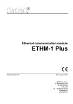
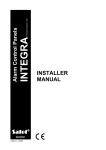
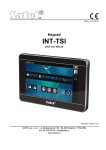
1
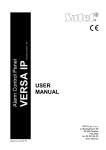
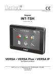
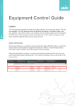
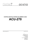
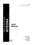
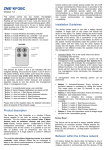
ABAX WIRELESS SYSTEM CONTROLLER ACU-270 Firmware version 5.00 acu-270_en 12/14 SATEL sp. z o.o. ul. Budowlanych 66 80-298 Gdańsk POLAND tel. + 48 58 320 94 00 [email protected] www.satel.eu WARNINGS The device should be installed by qualified personnel. Prior to installation, please read carefully this manual in order to avoid mistakes that can lead to malfunction or even damage to the equipment. Disconnect power before making any electrical connections. Changes, modifications or repairs not authorized by the manufacturer shall void your rights under the warranty. The SATEL's goal is to continually upgrade the quality of its products, which may result in alterations of their technical specifications and firmware. The current information on the introduced modifications is available on our website. Please visit us: http://www.satel.eu Hereby, SATEL sp. z o.o., declares that this device is in compliance with the essential requirements and other relevant provisions of Directive 1999/5/EC. The declaration of conformity may be consulted at www.satel.eu/ce The following symbols may be used in this manual: - note; - caution. CONTENTS 1. 2. 3. Introduction....................................................................................................................... 2 Features ........................................................................................................................... 2 Electronics board .............................................................................................................. 2 3.1 Terminals................................................................................................................... 3 3.2 DIP-switches.............................................................................................................. 3 3.2.1 Controller connected to the INTEGRA / INTEGRA Plus control panel ............... 3 3.2.2 Controller connected to the VERSA / VERSA Plus control panel....................... 3 3.3 LED ........................................................................................................................... 3 4. Installation of the controller............................................................................................... 3 5. Programming the controller .............................................................................................. 5 5.1 Parameters, options and functions ............................................................................ 5 6. Wireless devices............................................................................................................... 6 6.1 Wireless devices supported by the controller ............................................................ 7 6.2 Installation of wireless devices .................................................................................. 7 6.2.1 Work with the INTEGRA / INTEGRA Plus control panels................................... 8 6.2.2 Work with the VERSA / VERSA Plus control panels ........................................ 12 6.3 Programming the wireless devices .......................................................................... 12 6.3.1 Parameters and options ................................................................................... 12 6.3.2 Programming in the INTEGRA / INTEGRA Plus system .................................. 13 6.3.3 Programming in the VERSA / VERSA Plus system.......................................... 15 6.4 Specific character of the operation of wireless devices ........................................... 15 6.4.1 Wireless detectors............................................................................................ 16 6.4.2 Wireless sirens ................................................................................................. 16 6.4.3 Wireless expanders of hardwired zones and outputs ....................................... 17 6.4.4 230 V AC wireless controllers........................................................................... 18 7. Wireless keypads............................................................................................................ 18 7.1 Wireless keypads supported by the controller ......................................................... 18 8. APT-100 keyfobs ............................................................................................................ 18 8.1 Keyfobs in the INTEGRA / INTEGRA Plus system.................................................. 18 8.1.1 Adding the APT-100 keyfob by means of the DLOADX program ....................... 20 8.1.2 Removing the APT-100 keyfob by means of the DLOADX program .................. 20 8.2 Keyfobs in the VERSA / VERSA Plus system ......................................................... 21 9. Specifications ................................................................................................................. 22 2 ACU-270 SATEL 1. Introduction The ACU-270 controller works with the INTEGRA, INTEGRA Plus, VERSA and VERSA Plus control panels. It enables expansion of the security alarm system by adding the ABAX wireless devices and keypads. The ABAX system is based on two-way communication. All transmissions are acknowledged, which ensures that the information has been received and makes it possible to check the presence of devices in the system in real time. Configuration of parameters and testing of the ABAX system wireless devices is performed by radio, so dismounting of their enclosures is unnecessary. Additionally, the controller allows you to operate the security alarm system, using the ABAX system two-way keyfobs. The name plate of the controller is located on the enclosure base. After installation of the device, the name plate is not visible to the user. 2. Features Support for up to 48 ABAX system wireless devices (the number of supported devices depends on the control panel). Support for up to 8 ABAX system wireless keypads (the number of supported keypads depends on the control panel). Support for up to 248 APT-100 keyfobs (the number of supported keyfobs depends on the control panel). Two-way encrypted radio communication in the 868 MHz frequency band. Controller firmware update capability. Tamper protection in 2 ways – cover removal and tearing enclosure from the wall. 3. Electronics board SATEL ACU-270 3 Explanations to Fig. 1: terminals. RS-232 port (TTL standard) to enable updating the controller firmware. The controller can be connected to the computer using the USB-RS converter offered by SATEL. tamper contact. DIP-switches. 3.1 Terminals +12V COM CKM DTM CKE DTE A RS485 B - 3.2 3.2.1 power input. common ground. keypad bus clock. keypad bus data. expander bus clock. expander bus data. terminals provided for future applications (RS-485). DIP-switches Controller connected to the INTEGRA / INTEGRA Plus control panel The DIP-switches 1-5 are used for address setting. A numerical value is assigned to each switch. In OFF position, the value is 0. Numerical values assigned to individual switches in ON position are shown in Table 1. The sum of numerical values assigned to switches 1-5 means the address set on the device. The address must be different from that on the other devices connected to the expander bus of the control panel. DIP-switch number Numerical value 1 1 Table 1. 2 2 3 4 4 8 5 16 When connecting the controller to the control panel to which the ABAX system controller is already connected, it is recommended that a higher address be set in the new controller than that in the controller already connected to the control panel. 3.2.2 Controller connected to the VERSA / VERSA Plus control panel Set the switch 8 in ON position. The status of the other switches is irrelevant. 3.3 LED The LED indicates the status of communication with the control panel: ON – no communication with the control panel, blinking – communication with the control panel OK. 4. Installation of the controller Disconnect power before making any electrical connections. 4 ACU-270 SATEL The alarm system installation to which the controller is to be connected should be provided with: 2-pole disconnector, short-circuit protection with a 16 A time delay fuse. The controller should be installed indoors, in spaces with normal air humidity. Prior to installation you should plan the arrangement of all ABAX system wireless devices which are to be operated by the controller. Select the installation place so that these devices are located within the controller operating range. Remember that thick walls, metal partitions, etc. will reduce the range of the radio signal. It is recommended that the controller be mounted high above the floor. This will allow you to get a better range of radio communication and avoid the risk of the controller being accidentally covered by people moving around the premises. Mounting the controller near electrical installations is not advisable, as this may cause malfunction of the device. Several ABAX wireless system controllers can work within each other's range. Automatic synchronization with the wireless systems already in use is always performed when the controller is switched on, and after each operation of addition/removal of supported devices. The number of wireless devices working within each other's range depends on the RESPONSE PERIOD (see “Parameters, options and functions” p. 5) and can vary from 150 to 450. The higher the response frequency, the lower the number of devices that can work within each other's range. 1. Open the enclosure of the controller (Fig. 2). 2. Set the DIP-switches as required (see: “DIP-switches”). 3. Place the enclosure base against the wall and mark location of the mounting holes. Set the enclosure so that the cable entry opening is situated at the bottom of the enclosure or at the base. 4. Drill the holes in the wall for wall plugs (screw anchors). 5. Make the cable entry opening at the base. The opening diameter should not exceed 5 mm. The finished opening must not have sharp edges. 6. Run the cables through the opening made. 7. Using wall plugs (screw anchors) and screws, secure the enclosure base to the wall (Fig. 3). The plugs and screws are delivered with the device. If you wish to use another type of plugs and screws, you must bear in mind that the device, when installed, must withstand a pull-off force of at least 50 N. 8. Depending on the control panel to which the controller is to be connected: INTEGRA / INTEGRA Plus: connect the CKM, DTM, CKE, DTE and COM terminals to the corresponding terminals of the control panel communication buses (refer to the control panel installer manual). If the controller is not to support the wireless keypads, the CKM and DTM terminals do not need to be connected. VERSA / VERSA Plus: connect the CKE, DTE and COM terminals to the corresponding terminals of the control panel communication bus (refer to the control panel installer manual). It is recommended that an unshielded non-twisted cable be used to make the connection. If you use the twisted-pair type of cable, remember that the DTM and CKM / CKE and DTE (clock and data) signals must not be sent through one pair of twisted conductors. The conductors must be run in one cable. Prevent the cables from coming into contact with sharp edges to avoid damage to the cables. 9. Connect the power cables to the 12V and COM terminals. Use conductors with a crosssection of 1 – 2.5 mm2. The controller may be powered directly from the control panel, from an expander with power supply, or from a power supply unit with current limitation up to 3 A. SATEL ACU-270 5 10. Close the controller enclosure. 11. Power on the alarm system. 12. Start the identification function in the control panel (see the control panel installer manual). The module will be identified as “ACU-100”. 5. Programming the controller Programming of the controller is carried out by means of the control panel, using: the LCD keypad in service mode: – INTEGRA / INTEGRA Plus – the controller programming functions are available in the SETTINGS submenu (STRUCTURE HARDWARE EXPANDERS SETTINGS). Upon entering the submenu, a list of devices will be displayed. Using the and keys, find the controller name and press the key to get access to the list of functions. To program the controller name, use the NAMES submenu (STRUCTURE HARDWARE EXPANDERS NAMES). – VERSA / VERSA Plus – most of the controller parameters can be programmed in the 2. SETTINGS submenu (2. HARDWARE 1. KPDS & EXPS. 2. SETTINGS). Upon entering the submenu, a list of devices will be displayed. Using the and keys, find the controller name and press the key to start the "step by step" programming. The functions to start synchronization and to enter / exit the test mode are available in the 3. WIRELESS MOD. submenu (2. HARDWARE 1. KPDS & EXPS. 3. WIRELESS MOD.). the DLOADX program: – INTEGRA / INTEGRA Plus – in the "Structure" window, "Hardware" tab, after clicking on the controller name in the list of devices (Fig. 4); – VERSA / VERSA Plus – in the "Versa – Structure" window, "Hardware" tab, after clicking on the controller name. 5.1 Parameters, options and functions Name – individual name of device (up to 16 characters). Tamper signaled in partition – the partition in which tamper alarm will be triggered in the event of module tamper. No auto-reset after three module tamper alarms – if this option is enabled, the feature reducing the number of tamper alarms from the module to three is disabled (the feature prevents multiple logging of the same events and applies to successive uncleared alarms). Response period – communication with wireless devices takes place in specified intervals. The controller is then gathering information on the status of wireless devices and, if necessary, sending commands to the devices, e.g. switching the detectors to their active/passive state, switching on/off the test mode and/or changing configuration of the devices. The response period can be 12, 24 or 36 seconds. The less often communication between the controller and the wireless devices takes place, the more wireless devices can work within each other's operating range (12 seconds – up to 150, 24 seconds – up to 300, 36 seconds – up to 450). Beyond the response period, information about tampers of devices and violations of detectors operating in active mode are sent to the controller. The response period has an effect on the level of energy consumption by the wireless devices. The less often communication between the controller and the wireless devices takes place, the lower energy consumption and the longer battery life are. In the case of the AMD-103 detector, no communication takes place during polling. 6 ACU-270 SATEL Higher sensitivity for jamming detection – if this option is enabled, the sensitivity of detection of radio communication jamming is boosted. Synchronize – this function starts the procedure of synchronization, i.e. checking for presence of other ABAX wireless system controllers working within the controller operating range. The controller will synchronize the response period so that the radio transmissions of some controllers should not be mutually jammed. Synchronization is performed automatically upon starting the controller and after each operation of adding/removing devices supported by it. Test mode – in the ABAX system the test mode can be started, in which: – LED indicators are enabled in the wireless devices (the LEDs are disabled during normal operation) – information provided by means of the LEDs depends on the device; – signaling is blocked in the sirens. The test mode is started/ended during polling, which results in a delay, its duration depending on the programmed response period. The test mode will be turned off automatically after 30 minutes of: – starting the test mode from the DLOADX program (the 30-minute period is running from the moment of exiting the controller settings), – exiting the service mode in the control panel. According to requirements of the EN50131 standard, the level of radio signals sent by wireless devices is reduced during the test mode operation. For the AMD-103 detector, entering the test mode remotely is not possible. 6. Wireless devices The wireless keypads constitute a special category of devices and therefore they are discussed in a separate section. SATEL 6.1 ACU-270 7 Wireless devices supported by the controller Detectors AFD-100 – wireless water flood detector. AGD-100 – wireless glass-break detector. AMD-100 – wireless magnetic contact. AMD-101 – dual channel wireless magnetic contact. AMD-102 – wireless magnetic contact with input for roller shutter detector. AMD-103 – wireless magnetic contact. APD-100 – wireless passive infrared detector. APMD-150 – wireless dual motion detector. ARD-100 – wireless reorientation detector. ASD-110 – wireless smoke and heat detector. ATD-100 – wireless temperature detector [supported, if the controller works with the INTEGRA or INTEGRA Plus control panel]. AVD-100 – wireless vibration detector and magnetic contact. Sirens ASP-105 – wirelessly triggered outdoor siren. ASP-205 – wireless indoor siren. Other ACX-200 – hardwired zone / output expander. ACX-201 – hardwired zone / output expander with power supply. ARF-100 – radio signal level tester. ARU-100 – radio signal repeater [supported, if the controller works with the INTEGRA or INTEGRA Plus control panel]. ASW-100 E / ASW-100 F – 230 V AC wireless controller. 6.2 Installation of wireless devices After the control panel has identified the controller, you can begin installation of the ABAX system wireless devices. Before installing a wireless device, check the level of radio signal received by the device from controller and by the controller from device at the planned installation place. The ARF-100 tester is a useful tool to check the signal level. The level of signal received by device/controller may not be lower than 40%. If the radio signal level at the planned installation place is too low, select another installation location. Sometimes it is sufficient to move the device ten or twenty centimeters to obtain a significant improvement of signal quality. You can install the device permanently only after reaching the optimum level of radio signal. The wireless devices must be registered to the alarm system. This can be done using the LCD keypad or DLOADX program. The controller can support up to 48 wireless devices, but some devices take up more than one position on the list. For example, after adding to the system the ACX-200 expander module, which takes up 4 positions on the list of devices, the controller will still be able to handle 44 more wireless devices. The number of positions on the list is at the same time the number of zones and, in case of some devices, also outputs which will be taken by the device in the system. 8 ACU-270 SATEL The data relating to wireless devices are stored in the controller. If the controller with registered wireless devices is connected to the control panel, the wireless devices will be automatically assigned to the system zones/outputs during identification procedure. 6.2.1 Work with the INTEGRA / INTEGRA Plus control panels The number of supported wireless devices depends on the control panel. When adding and removing the wireless devices, remember that the identification function registers zones and outputs by groups of 8. Already after adding one wireless device which takes up 1 zone, the control panel will reserve 8 zones in the system for wireless devices. The LCD keypad makes it possible to select the zone to which that device will be assigned. Observe continuity, i.e. avoid leaving any gaps in the list, which will later reduce the number of available zones in the system. Remember to preserve continuity also when removing wireless devices. For example, if the devices registered in the controller occupy 9 positions on the list, then 16 zones (2x8) are reserved in the system. After removal of the device which occupied position 7 on the list, there will still be 16 zones (2x8) reserved in the system for wireless devices, although 8 positions are actually taken up on the list of wireless devices (see: Table 2). In such a case, it is recommended that the last devices be removed from the list and then added to the system again, so as to fill up the gap in the list and reduce the number of zones reserved for wireless devices. INTEGRA / INTEGRA Plus ACU-270 It.. 1 2 3 4 5 6 7 8 9 10 11 12 13 14 15 16 list of devices APD-100 detector APD-100 detector AMD-100 detector AMD-100 detector AMD-101 detector ^ ASP-105 siren ^ No 17 18 19 20 8 21 22 23 24 zones device APD-100 detector APD-100 detector AMD-100 detector AMD-100 detector AMD-101 detector AMD-101 detector unused/unavailable ASP-105 siren No 17 18 19 20 21 22 23 24 outputs device unused/unavailable unused/unavailable unused/unavailable unused/unavailable unused/unavailable unused/unavailable unused/unavailable ASP-105 siren 25 26 27 28 8 29 30 31 32 ASP-105 siren unused/unavailable unused/unavailable unused/unavailable unused/unavailable unused/unavailable unused/unavailable unused/unavailable 25 26 27 28 29 30 31 32 ASP-105 siren unused/unavailable unused/unavailable unused/unavailable unused/unavailable unused/unavailable unused/unavailable unused/unavailable Table 2. An example of how the wireless devices should not be registered. For devices taking up 8 positions, the system must reserve 16 zones and 16 outputs, as well as 2 addresses. SATEL ACU-270 INTEGRA / INTEGRA Plus ACU-270 It. 1 2 3 4 5 6 7 8 list of devices ASP-105 siren ^ APD-100 detector APD-100 detector AMD-100 detector AMD-100 detector AMD-101 detector ^ 9 No 17 18 19 20 8 21 22 23 24 zones device ASP-105 siren ASP-105 siren APD-100 detector APD-100 detector AMD-100 detector AMD-100 detector AMD-101 detector AMD-101 detector No 17 18 19 20 21 22 23 24 outputs device ASP-105 siren ASP-105 siren unused/unavailable unused/unavailable unused/unavailable unused/unavailable unused/unavailable unused/unavailable Table 3. An example of how to correctly register the wireless devices (compare also Fig. 5). For 8 devices, the system has reserved 8 zones and 8 outputs, as well as 1 address. In case of devices which, in addition to zones, also take up outputs, it is recommended that you add them to the system first. This will allow you to maintain the continuity of use of not the zones alone, but the outputs as well. Table 2 shows a situation in which the siren first output occupies position 8, and the second output – position 9. As a result, 16 outputs have been reserved for wireless devices in the system, though actually 2 outputs are used (the eighth output in the first group of 8 outputs and the first output in the second group of 8 outputs). In some cases, the gaps in the list of zones/outputs cannot be avoided. It applies to situation when the number of zones/outputs, which is used by the devices, is not a multiple of 8. For each group of 8 zones /outputs, one address on the expander bus is reserved. The controller can occupy from 1 to 6 addresses. This must be taken into account at the system design stage and sufficient number of free addresses must be left for the controller. If, when new wireless devices have been added to the controller, it turns out that next addresses are needed, and these are taken up by other devices, successful completion of the expander 10 ACU-270 SATEL identification procedure will be impossible. It will be necessary to change addresses of the devices connected to the bus. Adding new wireless devices For some wireless devices, you can select whether the device will take up one or two positions (channels) on the list of devices. Depending on the device, if one position is selected: AMD-102 – only additional inputs (roller shutter and NC) will be supported; ATD-100 – you will be able to program only one temperature threshold; AVD-100 – only the vibration detector will be supported. DLOADX program You can add wireless devices in the "Structure" window, "Hardware" tab, after clicking on the controller name in the list of devices. 1. Click on the “Read” button. The data related to wireless devices will be read from the controller (these data are not read after clicking on the button in the main menu). 2. Click on the “New device” button. The “New wireless dev.” window will open. 3. Enter the 7-digit serial number of the added device. The serial number can be found on the electronics board or on the enclosure. Each ARF-100 radio signal level tester has serial number 0000500. 4. Depending on the device type: ACX-200 / ACX-201: power-up the expander, ARF-100: turn on the device, ASW-100 E / ASW-100 F: insert the controller into 230 V AC socket, other devices: open the tamper contact. If an invalid serial number is entered, it will be indicated by a suitable message. In such a case, enter the correct serial number and repeat the above mentioned step. 5. The message will confirm that a new device has been added. It will be assigned to the first free zone from the pool reserved for the controller. A suggested name for that zone will appear (the name is editable). The name will be also assigned to the output, if the device is to be assigned to the output. For some devices, you can also select whether the device will take up one or two positions on the list of devices. 6. Click on the "OK" button. You can cancel adding the new device by pressing the "Cancel" button. You can also press the "Next" button to immediately begin adding another wireless device. 7. Click on the “Write” button. The data related to the new wireless device will be written to the controller (these data will not be written after clicking on the or button in the main menu). Having added new wireless devices, start the expansion module identification function. LCD Keypad You can add wireless devices in service mode, using the NEW DEVICE function (STRUCTURE HARDWARE EXPANDERS SETTINGS [controller name] NEW DEVICE). 1. Start the NEW DEVICE function. SATEL ACU-270 11 2. Enter the device 7-digit serial number and press the key. The serial number can be found on the electronics board or on the enclosure. Each ARF-100 radio signal level tester has serial number 0000500. 3. When the “Open device tamper” command is displayed, depending on the device type: ACX-200 / ACX-201: power-up the expander, ARF-100: turn on the device, ASW-100 E / ASW-100 F: insert the controller into 230 V AC socket, other devices: open the tamper contact. If you have entered a wrong serial number or the device has already been registered, a suitable message with relevant information will be displayed (press to return to the submenu). 4. Information about the device to be added will be displayed (type and serial number). Press the key 1 to confirm your intention to add a device. 5. If there is an option whether the device will occupy one or two positions (channels) on the device list, a suitable message with relevant information will be displayed. Press the key 1, if the device is to take up 1 position. Press the key 2, if the device is to occupy 2 positions. 6. Using the and keys, select the zone to which you want the device to be assigned, and then press . If the device occupies more than one position on the list of devices, additional zones, following the selected one, will be assigned to it automatically. 7. A message will be displayed to inform you that the expander identification function has been started. 8. After the devices have been identified, a new name of the zone will be displayed. You can change it. The same name will also be given to an output, if the device is to be assigned to the output. Press to save the name. If the device occupies two or more zones, the procedure of giving them a name will be repeated for each of them. Removing wireless devices DLOADX program You can remove wireless devices in the "Structure" window, "Hardware" tab, after clicking on the controller name in the list of devices. 1. Click on the “Read” button. The data related to wireless devices will be read from the controller (these data are not read after clicking on the button in the main menu). 2. Click on the device you want to remove (if the device occupies two or more positions on the list, you can click on any of them). 3. Click on the “Delete” button. The “Confirm” window will open. 4. Click on the “Yes” button. The “Confirm” window will close. 5. Click on the “Write” button. The device will be removed from the controller. Having removed a wireless device, start the expansion module identification function. LCD keypad You can remove a wireless device in the service mode, using the REMOVE DEVICE function (STRUCTURE HARDWARE EXPANDERS SETTINGS [controller name] REMOVE DEVICE). 1. Start the REMOVE DEVICE function. 2. Using the and keys, select the zone to which the device you want to remove is assigned, and then press . 12 ACU-270 SATEL 3. A prompt will appear on the display asking you whether the device is to be removed (the device type and serial number will be shown). Press the key 1. The device will be deleted. 4. A message on the display will inform you that the expander identification function has been started. After identification of the devices, return to the REMOVE DEVICE function will follow. 6.2.2 Work with the VERSA / VERSA Plus control panels The VERSA / VERSA Plus control panels can support up to 30 wireless devices. For information about operation of the ABAX system controller with the VERSA / VERSA Plus control panels, as well as adding and removing wireless devices, please refer to the installer manual of VERSA / VERSA Plus control panels. 6.3 6.3.1 Programming the wireless devices Parameters and options Filter – the number of consecutive response periods, during which communication with the device failed to be established, for the loss of communication with the device to be reported. Values from the 0 to 50 range can be entered. Entering the digit 0 will disable control of the device presence in the system. In the case of the AMD-103 magnetic contact, the presence check is performed in a different way than for the other ABAX system devices. If the value programmed for the FILTER parameter differs from 0, the lack of presence will be reported if no transmission from the AMD-103 magnetic contact is received within one hour. ARU – parameter available for a wireless device, if the ARU-100 repeater is registered in the controller (the controller is connected to the INTEGRA or INTEGRA Plus control panel). It allows you to define whether the device is to communicate to the controller directly, or via the selected ARU-100 repeater (several ARU-100 repeaters can be registered in the controller). The programming procedure is described in section “Programming in the INTEGRA / INTEGRA Plus system” (p. 13). Always active – the option is available for the most of wireless detectors. If enabled, the detector is permanently switched over to the active mode (see “Wireless detectors” p. 16). The AMD-103 detector and the wireless detectors assigned to 24-h zones are always in the active mode, therefore the ALWAYS ACTIVE option does not have to be enabled for them. Configuration – some of the wireless devices provide additional parameters and options, which can be configured by radio (shown in square brackets is information on the zone for which additional parameters can be programmed, if the device takes up more than 1 zone): AGD-100 – wireless glass-break detector. Sensitivity is to be programmed. AMD-100 / AMD-101 – wireless magnetic contact. The active reed switch is to be selected. AMD-102 – wireless magnetic contact with input for roller shutter detector. The following is to be programmed: active reed switch [first zone]; number of pulses after which alarm will be triggered by the roller shutter input [second zone]; time during which the specified number of pulses must occur for the roller shutter input to trigger alarm [second zone]. SATEL ACU-270 13 APMD-150 – wireless dual motion detector. The following is to be programmed: sensitivity of PIR sensor; sensitivity of microwave sensor; the way of operation in test mode. APD-100 – wireless passive infrared detector. The following is to be programmed: sensitivity, option of immunity to pets up to 15 kg. ARD-100 – wireless reorientation detector. Sensitivity is to be programmed. ATD-100 – wireless temperature detector. For both positions occupied by detector, the temperature threshold parameters can be programmed (thus two different temperature threshold can be programmed): threshold type: high (when the temperature rises above the defined temperature value, alarm will be triggered) or low (when the temperature drops below the defined temperature value, alarm will be triggered); temperature; tolerance. AVD-100 – wireless vibration detector and magnetic contact. The following is to be programmed: active reed switch [first zone]; sensitivity of vibration detector (registering a single vibration meeting the sensitivity criterion will cause alarm) [second zone]; the number of pulses which, if registered by vibration detector will cause alarm (the pulses need not meet the sensitivity criterion) [second zone]. Working parameters of the vibration detector are independently analyzed. The detector can trigger alarm after registering a single, strong vibration caused by a powerful impact, and also on registering several slight vibrations caused by a series of weak strikes. ASP-105 – wirelessly triggered outdoor siren. The following is to be programmed: type of acoustic signaling; maximum duration of acoustic signaling. ASP-205 – wireless indoor siren. Signaling parameters can be programmed for both positions occupied by the siren (thus allows to program two different signaling types): maximum duration of signaling; type of acoustic signaling; optical signaling option. ASW-100 E / ASW-100 F – 230 V AC wireless controller. Operating mode can be programmed. 6.3.2 Programming in the INTEGRA / INTEGRA Plus system DLOADX program You can program the wireless devices in the "Structure" window, "Hardware" tab, after clicking on the controller name in the list of devices (Fig. 4). Before making any changes, click on the "Read" button, and after making the changes – on the "Write" button (the data 14 ACU-270 relating to wireless devices are not read and saved after clicking on the SATEL button in the DLOADX program main menu). ARU In the "ARU" column: – leave the field blank, if the device is to communicate directly to the controller; – enter the ARU-100 repeater number in the list of wireless devices, if the device is to communicate to the controller via the repeater (the ARU-100 repeater takes up two positions on the list of devices – enter the number of the first of them). Configuration Described below is how the additional parameters and options should be programmed in the "Configuration" column. AGD-100 – enter a digit from the 1 to 3 range to set the sensitivity (1 – low , 2 – medium, 3 - high). AMD-100 / AMD-101 – enter the digit 0 (bottom reed switch) or 1 (side reed switch) to determine which of the two reed switches is to be active. AMD-102 – for the magnetic contact, enter the digit 0 (bottom reed switch) or 1 (side reed switch) to determine which of the two reed switches is to be active. For the roller shutter input, enter 2 digits: 1st digit – number of pulses: from 1 to 8. 2nd digit – pulse validity: 0 (30 seconds), 1 (120 seconds), 2 (240 seconds) or 3 (unlimited duration). APMD-150 – enter 3 digits: 1st digit – sensitivity of infrared path: from 1 to 4 (1 – minimum; 4 – maximum). 2nd digit – sensitivity of microwave path: from 1 to 8 (1 – minimum; 8 – maximum). 3rd digit – the way of operation in the test mode: 0 (alarm triggered after motion is sensed by both detectors), 1 (alarm triggered after motion is sensed by infrared detector) or 2 (alarm triggered after motion is sensed by microwave detector). APD-100 – enter 2 digits: 1st digit – sensitivity: 1 (low), 2 (medium) or 3 (high), 2nd digit – pet immunity option: 0 (disabled) or 1 (enabled). ARD-100 – enter a number from the 1 to 16 range to determine sensitivity (1 – minimum; 16 – maximum). ATD-100 – for each position taken by the detector, enter in turn: letter H (high temperature threshold) or L (low temperature threshold); numerical value corresponding to a temperature from the -30° C to +70° C range (with up to 0.5° accuracy), numerical value corresponding to a tolerance from the 0.5° C to 10° C range (with up to 0.5° accuracy). AVD-100 – for the magnetic contact, enter the digit 0 (bottom reed switch) or 1 (side reed switch) to determine which of the two reed switches is to be active. For the vibration detector, enter 2 digits: 1st digit – sensitivity: from 1 to 8 (1 – minimum ; 8 – maximum). 2nd digit – number of pulses: from 0 to 7. For the value 0, pulses are not counted. ASP-105 – enter 2 digits: 1st digit – type of acoustic signaling: from 1 to 4. SATEL ACU-270 15 2nd digit – maximum duration of acoustic signaling: 1 (1 minute), 2 (3 minutes), 3 (6 minutes) or 4 (9 minutes). ASP-205 – for both positions taken on the list by the siren, enter 3 digits: 1st digit – maximum duration of signaling: 1 (1 minute), 2 (3 minutes), 3 (6 minutes) or 4 (9 minutes). nd 2 digit – type of acoustic signaling: 0 (disabled), 1 (sound type 1), 2 (sound type 2) or 3 (sound type 3). rd 3 digit – optical signaling: 0 (disabled) or 1 (enabled). ASW-100 E / ASW-100 F – enter 0 (only remote control of the electric circuit); 1 (remote or manual control of the electric circuit) or 2 (remote or manual control of the electric circuit, but with option to manually block the remote control). LCD keypad You can configure the wireless devices in service mode, using the following functions: USE ARU-100, ACTIVE MODE, CONFIGURATION and FILTER (STRUCTURE HARDWARE EXPANDERS SETTINGS [controller name]). Having started the function, use the and keys to select the zone to which the wireless device is assigned and press the key. Use ARU-100 Using the and keys select whether the wireless device is to communicate to the controller directly, or via a selected repeater (the name of the zone to which the repeater is assigned is displayed on the list). Configuration Use the arrow keys for programming additional parameters and options. The values which can be programmed for individual parameters of wireless devices are presented in the section describing configuration of the devices by means of the DLOADX program. 6.3.3 Programming in the VERSA / VERSA Plus system DLOADX program You can configure wireless devices in the "Versa – Structure" window, "Hardware" tab, after clicking on the controller name in the list of devices. Proceed in the same way as when programming in the INTEGRA / INTEGRA Plus system. Before making any changes, click on the "Read" button, and after making the changes – on the "Write" button (the data relating to the wireless devices are not read after clicking on the the button or saved after clicking on button in the DLOADX program main menu). LCD keypad For information on configuring wireless devices from the LCD keypad, please refer to the VERSA / VERSA Plus control panel programming manual. 6.4 Specific character of the operation of wireless devices This chapter describes the peculiar character of the operation of individual groups of wireless devices, which affects the method of programming the zones and outputs to which the wireless devices are assigned. 16 6.4.1 ACU-270 SATEL Wireless detectors The wireless detectors send information on violations, tampers and low-battery status. The information on violations and tampers is sent to the zones to which the detectors are assigned. You can program these zones as: NC, NO or EOL – the zone will inform about detector violation; 2EOL/NC or 2EOL/NO – the zone will inform about detector violation and tamper. The mode of operation of wireless detectors depends on the status of partition to which the zone with wireless detector belongs: partition disarmed – the detector operates in passive mode. It is a battery saving mode, in which communication with the controller takes place mainly during time intervals determined by the RESPONSE PERIOD parameter. At that time, information on violations and battery status is sent. Only detector tampers are sent immediately. partition armed – the detector operates in active mode. The detector sends immediately all information to the controller. Because switching the detectors over from the passive into active mode and conversely takes place during the response time, it is performed with some delay in relation to arming/disarming. The maximum delay – depending on the selected response frequency – can be 12, 24 or 36 seconds. The AMD-103 detector and wireless detectors assigned to the 24-hour zones, which are permanently armed, are in the active mode at all times. Also other wireless detectors can always work in the active mode, if the ALWAYS ACTIVE option is enabled for them (see “Parameters and options” p. 12). According to the EN50131-3 standard all ABAX system Hold-Up devices must be always in active mode. Batteries ensure approx. 3 years operation of the detectors, assuming that the detectors are in passive state for part of that period and the RESPONSE PERIOD is 12 seconds. A longer response period (24 or 36 seconds) means extension of the battery life time. The battery life time in the detectors switched permanently into the active mode is shorter than in those which are periodically switched to the passive mode. However, if the specific character of a detector or its installation place is such that the number of violations is low, switching the detector permanently into the active mode will not adversely affect the battery life time. 6.4.2 Wireless sirens The wireless sirens take up 2 outputs and 2 zones in the system. How the signaling is controlled by the outputs depends on the siren: ASP-105 – the first of the outputs to which the siren is assigned controls the acoustic signaling. Parameters of the acoustic signaling are programmed for the siren (type and maximum duration of the sound signal). The second output controls the optical signaling. The optical signaling is enabled when the output is active. The command to start and stop signaling is sent to the siren immediately. ASP-205 – both outputs to which the siren is assigned control both the acoustic and optical signaling. Parameters of the signaling triggered by each of the outputs are programmed separately for the siren. Thus two different, independently triggered ways of signaling can be configured. As a result, the outputs can separately control the optical and acoustic signaling or signal different alarm types (e.g. burglary and fire). The command to start the signaling is sent to the siren only during the response time. Therefore, the cut-off time for the control panel outputs which control the siren must be longer than the response period. SATEL ACU-270 17 It is recommended that cut-off time correspond to maximum duration of signaling programmed for the siren. The zones in the system to which the wireless sirens are assigned can be programmed as: NC, NO or EOL – the zone will inform about power failures; 2EOL/NC or 2EOL/NO – the zone will inform about power failures and tamper. The type of zones to which the wireless siren is assigned should be matched to the information sent: ASP-105 – first zone: low battery and tamper; second zone: external 12 V DC power loss and tamper. ASP-205 – both zones: low battery and tamper. The tamper information is sent immediately, while the trouble information – during the response time. Tamper alarm on opening the tamper switch in the siren: ASP-105 – lasts for the maximum time of acoustic signaling programmed for the siren (sound type selected during programming and optical signaling); ASP-205 – lasts 3 minutes (sound type 1 and optical signaling). After starting the SERVICE MODE or TEST MODE and for 40 seconds after power-up, the signaling in the siren is blocked. It enables installation work to be carried out. Opening the tamper switch will not trigger loud signaling, but information on tamper will be sent (when in service mode, the control panel will not signal the tamper alarms). The command to block/unblock the signaling connected with starting / ending the test mode or the service mode is sent during the response time. 6.4.3 Wireless expanders of hardwired zones and outputs The wireless expander of hardwired zones and outputs (ACX-200 or ACX-201) takes up 4 zones and 4 outputs in the system. The alarm system zone / output to which the zone / output in ACX-200 or ACX-201 expander is assigned is programmed in the same way as the other hardwired zones / outputs of the control panel. You should remember however that sensitivity of the expander zones may be different from that programmed in the control panel: – from 20 ms to 140 ms – the same as the value programmed in the control panel; – above 140 ms – only some values are available: 300 ms, 500 ms, 700 ms, etc. every 200 ms (the programmed value is rounded up to that supported by the expander). The EN50131-3 standard requires that zones must react to signals lasting more than 400 ms. It means in case of the wireless expanders of hardwired zones and outputs that no values exceeding 300 ms should be entered when programming the sensitivity (the higher the value, the lower the sensitivity). The expansion module informs you about the zone status as it changes. Also the expander outputs are controlled in real time. Only the programming of zones takes place during the response time (in one period, data relating to configuration of one zone are sent to the expander module, i.e. sending the information on settings of four zones require four response periods). If communication with the controller is lost, all previously activated outputs will be deactivated after 20 response periods. Additionally, the ACX-201 expander module sends information about: status of AUX1 and AUX2 power supply outputs – information on overload is sent when the AUX1 or AUX2 output load exceeds 0.5 A. 18 ACU-270 SATEL battery status – information on low battery is sent when the battery voltage drops below 11 V for more than 12 minutes (3 battery tests). The expander will kept sending this information to the controller until the battery voltage rises and remains above 11 V for longer than 12 minutes (3 battery tests). AC power status – information on the loss of power supply is sent when the AC power loss lasts for more than 30 seconds. The AC power restore is reported with the same delay. 6.4.4 230 V AC wireless controllers Activation of the output to which the controller is assigned will result in energizing the 230 V AC electrical circuit (if reverse polarity of the output has been programmed, the circuit will be deenergized). Depending on the operating mode, information on the button status (mode 0) or on the electric circuit status (mode 1 and mode 2) is sent to the zone to which the controller is assigned. Information on the button status is sent in real time. Information on the electric circuit status is sent during the response time. Pressing the button / closing the electric circuit means violation of the zone to which the controller is assigned. 7. Wireless keypads The wireless keypads constitute a special category of wireless devices for which a separate group of positions is reserved in the controller. 7.1 Wireless keypads supported by the controller VERSA-LCDM-WRL – wireless keypad designed for operating the VERSA / VERSA Plus control panel. INT-KWRL – wireless keypad designed for operating the INTEGRA / INTEGRA Plus control panel. For information about installation and configuration of the wireless keypads, refer to the manuals delivered with the respective keypads. The data related to wireless keypads are stored in the controller. If the controller with registered wireless keypads is connected to the control panel, the keypads will be added to the system during identification procedure. However, if their addresses coincide with those of other devices installed in the system, the identification procedure will fail. 8. APT-100 keyfobs The maximum number of supported keyfobs depends on the maximum number of the control panel users. The data related to keyfobs are stored in the controller. After the controller containing keyfob data is connected to the control panel, keyfobs will be automatically assigned to the existing users. 8.1 Keyfobs in the INTEGRA / INTEGRA Plus system The user can have one APT-100 keyfob. If more than one ABAX wireless system controllers are connected to the INTEGRA / INTEGRA Plus control panels, the keyfob will be supported by all of them. The keyfob data are automatically saved to all controllers. SATEL ACU-270 19 When connecting the controller to the INTEGRA 128-WRL control panel or to the control panel to which the ABAX system controller is already connected, you should make uniform the data relating to APT-100 keyfobs. In the keypad service mode, the COPY ABAX KFOBS function is available (STRUCTURE HARDWARE EXPANDERS COPY ABAX KFOBS), which enables copying of the keyfob data. In the case of the DLOADX program, to write to a new controller the data on APT-100 keyfobs already assigned to the users, open the "Keyfobs ABAX" window and: INTEGRA 128-WRL – click on the "Write to all" button (the button is available, when the ABAX system controller is connected to the control panel). other INTEGRA / INTEGRA Plus control panels – click on the "Read" button and immediately after reading the data, click on the "Write" button (after the data are read, you must not make any changes). The functions are executed by means of controlling the status of system zones. Using the keyfob, you can control up to 6 zones in the alarm system. These zones should not exist physically and the wiring type programmed in them must be different from NO DETECTOR and FOLLOW OUTPUT. You can program any function for these zones. Pressing the keyfob button (or two buttons simultaneously) will violate the zone and cause suitable reaction from the control panel. On pressing any keyfob button (not necessarily the one used to control a system zone), information on the status of three selected system outputs will be presented on the keyfob LEDs. Thus you can get confirmation that the function has been executed or information on the current system status. The outputs whose status is presented by means of the keyfob LEDs do not have to exist physically. The installer can indicate up to 8 outputs in the system which will be used to inform the keyfob users (ABAX CONFIRMAT. function in the keypad [SERVICE MODE STRUCTURE HARDWARE EXPANDERS ABAX CONFIRMAT.] or "Keyfobs ABAX" window in the DLOADX program). Pressing a button / combination of buttons in the keyfob can generate a keyfob use event. For information on adding / removing keyfobs by means of the keypad please refer to the control panel user manual. 20 ACU-270 SATEL In the DLOADX program, you can add and remove keyfobs in the "Keyfobs ABAX" window (Fig. 6). The window opening command is available in the "Users" menu. Before making any changes, click on the "Read" button, and after making the changes – on the "Write" button (the data related to keyfobs are not read and saved after clicking on the button in the DLOADX program main menu). Removal of a keyfob will not erase its settings (dependences between the buttons and zones, confirmation rules, etc.). When added to the user, the new keyfob will have the same settings as the deleted one. You can remove all keyfobs, including their settings, by means of the REM.ABAX KEYFOB function available in the service mode in the keypad (STRUCTURE HARDWARE EXPANDERS REM.ABAX KEYFOB). 8.1.1 Adding the APT-100 keyfob by means of the DLOADX program Entering the serial number manually 1. Click on the field in the "S/N" column next to the name of the user to whom you want to assign a keyfob. 2. Enter the keyfob serial number and confirm by pressing ENTER. Reading the serial number during transmission 1. Click on the field in the "S/N" column next to the name of the user to whom you want to assign a keyfob. 2. Click on the "New" button. The "New" window will open. 3. According to the command which will appear in the window, press the keyfob button. 4. When the keyfob serial number is displayed in the window, click on the "OK" button. The "New" window will close. The serial number of the new keyfob will be shown in the "S/N" column. Assigning new function to the keyfob button (combination of buttons) 1. Click on the field corresponding to the button (combination of buttons) to which you want to assign a zone. 2. Enter the zone number and press ENTER to confirm. 3. Using the SPACE key enable/disable the event generating function. If the symbol is displayed next to the zone number, the event will not be saved after pressing the button / combination of buttons (if no symbol is displayed, the event will be saved). Assigning outputs to the LEDs 1. Click on the field in the "LED" column. 2. Using the keyboard, enter up to 3 digits. Each of the digits must correspond to the number of field with output selected for confirmation (on the window right side) i.e. it can be from the 1 to 8 range. The names of outputs in fields designated with these digits will be shown in bold-type face. 8.1.2 Removing the APT-100 keyfob by means of the DLOADX program 1. Click on the field in "S/N" column next to the name of user whose keyfob is to be removed. 2. Click on the "Delete" button. 3. In the window which will be displayed, click on the “Yes” button to confirm that you want to remove the keyfob. The keyfob serial number shown in the "S/N" column will be erased. SATEL 8.2 ACU-270 21 Keyfobs in the VERSA / VERSA Plus system The functions which can be started using the keyfobs and the information that can be presented on the LEDs are described in manuals for the VERSA / VERSA Plus control panels. After a keyfob has been added, its settings will be configured automatically, based on the user schedule. These settings can be modified (different functions can be assigned to the buttons / combination of buttons and different information to the LEDs). The user manual for VERSA / VERSA Plus control panels describes the procedures for adding and editing the user by means of the keypad, during which you can add or remove the keyfob and program its settings. In the DLOADX program, you can add and delete keyfobs in the "Versa – Structure" window, "Hardware" tab, after clicking on the controller name in the list of devices, and then on the "Keyfobs" tab (Fig. 7). Before making any changes, click on the "Read" button, and after making the changes – on the "Write" button (the data relating to keyfobs are not read after clicking on the button or saved after clicking on the button in the DLOADX program main menu). Removal of a keyfob by means of the keypad will not erase its settings (the functions assigned to the buttons). When added to the user, the new keyfob will have the same settings as the deleted one. You can remove all keyfobs, including their settings, by means of the REM.ABAX KFBS function available in the service mode in the keypad (2. HARDWARE 1. KPDS. & EXPS. 8. REM.ABAX KFBS). Adding and removing a keyfob with the DLOADX program is carried out in the same way as for the INTEGRA and INTEGRA Plus control panels. You can assign functions to the buttons (combination of buttons) in the following way: 1. Click on the field corresponding to the selected button (combination of buttons). 2. Right click on your mouse. A drop-down menu will appear in which you are to select the new function. 22 ACU-270 SATEL In order to determine the information which will be presented on the LEDs: 1. Click on the field corresponding to the selected LED. 2. Right click on your mouse. A drop-down menu will appear in which you are to select the new information. 9. Specifications Supply voltage ................................................................................................... 12 V DC ±15% Standby current consumption ..........................................................................................47 mA Maximum current consumption ........................................................................................75 mA Operating frequency band................................................................... 868.0 MHz ÷ 868.6 MHz Radio communication range (in open area) ............................................................ up to 500 m Security grade according to EN50131-3 ....................................................................... Grade 2 Complied with standards. EN 50130-4, EN 50130-5, EN 50131-1, EN 50131-3, EN 50131-5-3 Environmental class according to EN50130-5 .........................................................................II Operating temperature range.............................................................................-10 °C...+55 °C Maximum humidity ..........................................................................................................93±3% Enclosure dimensions ................................................................................... 26 x 112 x 29 mm Weight................................................................................................................................. 48 g