Transcript
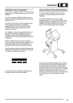
HARDWARE
Vehicle Communication Serial Interface (VCSI)
The vehicle communication serial interface (VCSI)
allows TestBook to communicate with specified
electronic control units (ECUs) and other devices
that follow the ISO9141 standard. This international
standard specifies the requirements for setting up
the interchange of digital information between
on-board ECUs of road vehicles and diagnostic
testers.
The ISO 9141 support consists of three main
functional blocks: the asynchronous serial
receiver/transmitter, counter/timers and the ISO
9141 physical interface. The asynchronous serial
receiver/transmitter and counter/timer logic are
implemented using a field programmable gate array
(FPGA). The physical interface is electrically isolated
from TestBook. TestBook VCSI can achieve a baud
rate synchronization from 10 to 10K baud.
TestBook is capable of operating, while not
connected to a vehicle, for no more than 15 minutes
based on a fully charged new battery. The system
clock and configuration RAM on the system board in
TestBook is battery backed up with a NiCAD
(nickel-cadmium) battery.
Mechanical Design
TestBook is composed of two separate enclosures,
a display unit and a base unit. The display unit
houses the display, speaker and touch screen. The
base unit houses all other electronics. The display
unit is attached to the base unit through a pivot
mechanism which allows it to be angled for normal
use, folded down for transporting or removed for
remote usage. The display unit is tethered to the
base unit with one thin cable, allowing it to be easily
moved around the vehicle.
Base Unit Enclosure
Power Sources
TestBook can be connected directly across the
vehicle battery terminals. In this mode of operation
the VCSI and VOM isolations will keep the vehicle
battery ground isolated from the signal ground. The
isolated DC to DC converter will provide the ground
isolation for the peripheral connectors such as the
parallel and serial ports. The peripheral signals are
not isolated. TestBook can also be powered from an
external AC to DC power supply. This mode is
especially useful to recharge TestBook internal
battery while not in use.
When connected to the vehicle TestBook uses DC
power from the vehicle, with a voltage range of 9.7 V
DC to 16V DC. If the vehicle power is lost or
TestBook is disconnected from the vehicle,
TestBook operates from its internal battery pack.
The base unit enclosure consists of sheet metal
parts that form a protective environment for the main
electronics. The enclosure has rubber bumpers at
strategic points to absorb shock from accidental
drops. There is a handle at the top of the unit for
transporting it. The display module has a storage
location on the base unit. The display can be stored
with the LCD facing the base unit. This configuration
will protect the LCD during transportation. The
display module can also be placed so the LCD faces
away from the base unit to allow the user to interface
with the tester without hand holding the display.
Cables and Adapters
The TestBook package contains the road test power
supply. This cable has been designed to operate in
the harsh automotive garage environment. The road
test power supply connects TestBook to the vehicle
battery. This cable is 4.2 metres long. It has red and
black battery clamps at one end and a sub-miniature
D power connector at the other. A black PVC
molded fuse box is located near the clamp end.
7