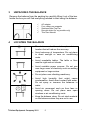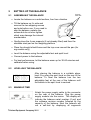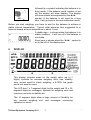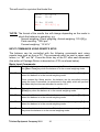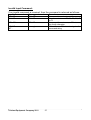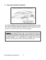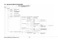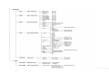
1
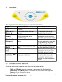
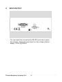
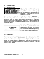
Adam Equipment PGW..M SERIES (P.N. 8723, Revision B1, July 2011) Software rev.: 3.38 or above © Adam Equipment Company 2011 © Adam Equipment Company 2011 TABLE OF CONTENTS 1 2 3 4 5 KNOW YOUR BALANCE .............................................................................................3 SPECIFICATIONS........................................................................................................4 UNPACKING THE BALANCE ......................................................................................5 LOCATING THE BALANCE .........................................................................................5 SETTING UP THE BALANCE ......................................................................................6 5.1 ASSEMBLING THE BALANCE .............................................................................6 5.2 LEVELLING THE BALANCE .................................................................................6 5.3 WARM-UP TIME ...................................................................................................6 6 DISPLAY ......................................................................................................................7 7 KEYPAD .......................................................................................................................9 7.1 NUMERIC ENTRY METHOD ................................................................................9 8 INPUT/OUTPUT .........................................................................................................10 9 OPERATIONS ............................................................................................................11 9.1 INITIALISATION ..................................................................................................11 9.2 PASSCODES ......................................................................................................11 9.3 WEIGHING ..........................................................................................................12 9.3.1 Weighing Units .............................................................................................12 9.4 FUNCTIONS........................................................................................................13 9.4.1 Parts Counting..............................................................................................13 9.4.2 Percent Weighing .........................................................................................14 9.4.3 Check Weighing ...........................................................................................15 9.4.4 Animal / Dynamic Weighing..........................................................................17 9.4.5 Net / total ......................................................................................................20 9.4.6 Density Determination ..................................................................................21 10 CALIBRATION ........................................................................................................23 10.1 MANUAL CALIBRATION.....................................................................................23 10.2 AUTOMATIC CALIBRATION...............................................................................23 11 RS-232 INTERFACE...............................................................................................24 12 ERROR CHECKING ...............................................................................................28 13 SUPERVISOR MENUS...........................................................................................29 13.1 ENABLE WEIGHING UNITS ...............................................................................29 13.2 ENABLE WEIGHING MODES.............................................................................29 13.3 ENABLE SERIAL INTERFACE PARAMETERS..................................................30 13.4 SETUP PARAMETERS.......................................................................................32 13.5 PASSCODES ......................................................................................................33 13.5.1 Forgotten Passcodes......................................................................................34 14 PERIPHERALS .......................................................................................................34 15 SAFETY AND MAINTENANCE...............................................................................35 16 TROUBLE-SHOOTING...........................................................................................35 17 BALANCE SECURITY SEALING............................................................................41 18 BALANCE MENU DIAGRAMS................................................................................44 19 REPLACEMENT PARTS AND ACCESSORIES .....................................................46 20 SERVICE INFORMATION ......................................................................................46 © Adam Equipment Company 2011 1 © Adam Equipment Company 2011 2 1 KNOW YOUR BALANCE Thank you for selecting the PGW..M series of balance. This Instruction Manual will familiarise you with the installation, accessories, trouble-shooting, after sales service information, general maintenance of the balance, etc. and will guide you through the various applications. Please read this Manual thoroughly before starting the operation. If you need any clarifications, feel free to contact your supplier or Adam Equipment. PRODUCT OVERVIEW The PGW..M balances are ideal for laboratory and general purpose weighing. The balances can also be used for some advanced weighing functions. The balances are configured at the factory for compliance with EN 45501, OIML R-76. FEATURES: PGW..M series • Large easy to read LCD display with backlight • Standard applications include weighing, check weighing, percentage weighing, parts counting, animal / dynamic weighing, net / total and density determination • Automatic and semi-automatic span adjustment is done with internal calibration mass only. It is operational after 5 minutes of switching the balance on, when the temperature changes by 2ºC and on every 4 hrs after switching on. This function can not be disabled by user. • The weight values on the display and the RS-232 output are marked with brackets on the least significant digit. • Can be configured to print a GLP Compliant report after each calibration to include the time, date, balance number and a verification of the calibration • Automatic temperature compensation • Display in 4 languages- English, French, German and Spanish • Capacity tracker • Date and time • Easy to use, sealed keypad • Below balance weighing facility • Password protection • Security locking point © Adam Equipment Company 2011 3 2 SPECIFICATIONS Model* Maximum capacity e= Readability d= Tare range Class Units of measure Interface Operating temperature Power supply Calibration Display Draught shield Housing Pan size Overall dimensions (w x d x h) Net weight Applications PGW 153M 150g PGW 253M 250g PGW 453M 450g PGW 753M 750g PGW 1502M 1500g PGW 2502M 2500g 0.01g 0.001g PGW 3502M 3500g PGW 4502M 4500g 0.1g 0.01g Full II grams, milligrams (for 0.001g units only), kilograms, carats RS-232 bi-directional 15°C - 35°C 15 VDC, 50/60 Hz, 800 mA Internal Calibration- Manual or Automatic Backlit LCD with dual digits (24 mm high) and capacity tracker Supplied as standard Not applicable Die cast aluminium housing (glass weighing chamber for models with 1mg readability) 140×140mm 192×192mm 251 × 358 × 104 mm 5.5 kg Weighing, Check weighing, Percentage weighing, Parts counting, Animal / dynamic weighing, Net / total and Density determination © Adam Equipment Company 2011 4 3 UNPACKING THE BALANCE Remove the balance from the packing by carefully lifting it out of the box. Inside the box you will find everything needed to start using the balanceAC adapter Four rubber pan supports Stainless Steel Top Pan Draught shield (for mg models only) This User Manual 4 LOCATING THE BALANCE • The balance should not be placed in a location that will reduce the accuracy. • Avoid extremes of temperature. Do not place in direct sunlight or near air conditioning vents. • Avoid unsuitable tables. The table or floor must be rigid and not vibrate. • Avoid unstable power sources. Do not use near large users of electricity such as welding equipment or large motors. • Do not place near vibrating machinery. • Avoid high humidity that might cause condensation. Avoid direct contact with water. Do not spray or immerse the balances in water. • Avoid air movement such as from fans or opening doors. Do not place near open windows or air-conditioning vents. • Keep the balance clean. Do not stack material on the balances when they are not in use. © Adam Equipment Company 2011 5 5 SETTING UP THE BALANCE 5.1 ASSEMBLING THE BALANCE Screws with nuts • Locate the balance on a solid surface, free from vibration • Tilt the balance on it’s side and remove the two shipping screws and nuts before use. If you need to ship the balance, replace the screws but do not over-tighten which may damage the internal mechanisms Label • Gently place the 4 pan supports (if not already fitted) and then the stainless steel pan on the weighing platform • Place the draught shield frame and the top cover around the pan (for mg models only) • Level the balance using the adjustable feet and spirit level • Connect power to the balance • For best performance, let the balance warm up for 30-60 minutes and calibrate before using 5.2 LEVELLING THE BALANCE After placing the balance in a suitable place, level it by using the spirit level on the rear of the balance. To level the balance turn the two adjustable feet at the rear of the balance until the bubble in the spirit level is centred. 5.3 WARM-UP TIME Attach the power supply cable to the connector on the rear of the balance. Plug the power supply module into the mains. The display will indicate the balance serial number (if set) and the software revision number followed by the capacity of the balance. Next the balance will run a self-test by displaying all segments © Adam Equipment Company 2011 6 followed by a symbol indicating the balance is in busy mode. If the balance serial number is not set the display will show dashes. The display will show zeroes accompanied by the 0 symbol. If the balance is not used for a long time, it will go back to the auto-calibration mode. Before you start weighing, you have to wait for the balance to achieve a stable internal temperature. Typical initial warm-up time suggested for a balance already at room temperature is about 1 hour. A stable sign ~ is shown when the balance is in stable condition. It will turn off if the balance is not stable. Exact zero is shown when the “ 0 “ symbol is on to the left of the display area. 6 DISPLAY This display includes areas for the weight value (up to 7 digits), symbols for common weighing units, tare, stability, zero, arrows used for check weighing, a 0-100% bar graph and a text area for menu. The LCD has 7 x 7-segment digits for the weight and 10 x 14segment digits for messages, symbols for weighing units and common use such as stability etc. The 14 segment digits allow a large amount of flexibility for any unusual weighing unit, and messages concerning operation or errors. © Adam Equipment Company 2011 7 The Percentage indicator known as capacity tracker has 10 large segments for showing the percentage of the total range used. This is also used during check-weighing. The 10 digit text area is used to display the current weighing mode or to guide the user through processes such as density determination. SYMBOLS AND TEXT The LCD has unique symbols to indicate the following: 0 Zero Busy Stable A bar graph with set point markers g, mg, kg, ct g/cc, Pcs, %, M, and S Symbols shown for the units and modes INDICATORS When calibration is occurring or about to occur “CAL” When a temperature is shown or a temperature driven “ºC” “ti” “Net” “PARTS” “PERCENT” “NT” “0%”, “100%” calibration is to occur For a time driven calibration When a net weight is shown When the balance is in the Parts counting mode When the balance is in the Percent weighing mode When the balance is in the Net/ Total mode When the capacity tracker is showing percent of maximum range used © Adam Equipment Company 2011 8 7 KEYPAD The keypad has the following keys to operate the balance. Keys Primary function Secondary function To turn the balance to ON or Standby [ 0/T] or A combined zero and tare To escape from setup [Esc] function functions and modes [Unit] / or Selects weighing units by To decrement or change a [Down] cycling through a set of displayed value or scroll through options backwards enabled units [Mode] / or Enters the Mode Selection To advance a flashing digit [Advance] Menu by one position to the right. To go back by one step during setup functions [Print] / or Instructs the balance to print To advance a flashing digit [Back] data by one position to the left [Cal] / or Starts the calibration function To increase or change a [Up] displayed value or scroll through options forward [Setup]/ Enters the Setup parameters Enters a function or saves or [Enter] (Supervisor Menus) a value while manually manually entering unit weight or check weighing limits 7.1 NUMERIC ENTRY METHOD To set a value when required, use the keys as given below- [Up] and [Down] keys to increase or decrease the flashing digit, - [Advance] and [Back] keys to advance or move back the digit and - [Enter] key to accept the value © Adam Equipment Company 2011 9 8 INPUT/OUTPUT The rear panel has connectors for RS-232 serial and a power input socket. Required power input is a low-voltage external supply, 15VDC @ 800mA. © Adam Equipment Company 2011 10 9 OPERATIONS 9.1 INITIALISATION When the balance is first switched on, it will display the balance serial number (if set), software revision, model capacity and then all segments on the display will be shown. Overall the time taken is usually 5 -10 seconds. If an operator passcode has been set, the display will show “PASSCODE” and the main display will show a zero. In this case you must enter the passcode to continue using the numeric entry method (see section 7.1). A different passcode may be set for a Supervisor to weigh or to have access to the selected User menus. If the passcode has not been set the balance will continue as below. The display will show zero reading along with the zero symbol “ 0” and the weighing unit last used. If automatic time calibration is enabled the balance will calibrate 15 minutes after power up or again after the pre-set time interval. 9.2 PASSCODES If a passcode has been set to limit access to the weighing functions of the balance the display will show “PASSCODES” with the main digit set to zero. Use the numeric entry method (see section 7.1) to enter the code. The display will change to show 7 digits set to zero with the rightmost digit flashing. Make sure to enter the correct passcode to continue. See the Section 13.5 for details. © Adam Equipment Company 2011 11 9.3 WEIGHING • Press [ • “ 0/T] to zero the balance, if required 0 “ will be displayed • Place a mass on the pan and the weight will be displayed • If a container is used press [ 0/T] to tare the balance when the balance symbol “~” is on. “Net” will be displayed to indicate that the balance is tared • When the display shows zero, place the item to be weighed. Only the net weight will be displayed. The capacity tracker at the bottom of the LCD will indicate the weight graphically with respect to the maximum weighing capacity • At any time the [Unit] key may be pressed to select another unit. Use the [Up] or [Down] key to scroll through the units and select the desired unit by pressing [Enter], the display will change to show the weight in the selected weighing unit. The available weighing units can be enabled or disabled by the user (see section 13.1). Only weighing units that have been enabled will be cycled through when [Unit] is pressed 9.3.1 Weighing Units You can select alternative weighing units to display the weight by pressing the [Unit] key. The available weighing units are: Unit Symbol Models g All Conversion Factor 1g = 1 Conversion Factor 1 unit = grams 1.0 1 GRAMS 2 MILLIGRAMS mg not 0.01g units 1000 0.001 3 KILOGRAMS kg All 0.001 1000 4 CARATS ct All 5 0.2000 It is possible to set the balance to display only grams. Grams will always be one of the units enabled, by default. The balance displays the alternate weighing units with as much precision as possible. For example, the 450g x 0.001g balance could weigh up to: Unit g. Mg Kg ct. Maximum 450g 450000 0.450000 2250 © Adam Equipment Company 2011 12 d= 0.001 1 0.000001 0.01 9.4 FUNCTIONS When weighing, the user can access the applications that have been enabled (see section 13.2). The following applications are available: • Weighing • Parts counting • Percent weighing • Check weighing • Animal / dynamic weighing • Net / total • Density determination The selectable functions can be enabled using a similar method to the Units above by turning the functions on or off. 9.4.1 Parts Counting This allows the user to weigh a sample of parts to compute an average unit weight and then determine the number of items being weighed by dividing the net weight by the unit weight value. The result is always a whole number of parts. The balance will have a preset number of parts to be used as a sample. These values are 10, 25, 50 or 100 items. Steps: • Press [Mode] to show parts counting, “PARTS” will be displayed • Enter parts counting by pressing [Enter] • Press the [Up] or [Down] key to select the sample size, “REF QTY”, 10, 25, 50, 100, etc., then press [Enter] to confirm • When “LOAD XX Pcs” is shown place XX number of items on the pan and press [Enter] to compute the average piece weight. Display will indicate the total weight in the last selected unit and then show “XX Pcs” sounding a beep. A message “PARTS” will be prompted on the top of the display to indicate that the balance is in the parts counting mode • Remove the sample and display will show “0 Pcs”. © Adam Equipment Company 2011 13 • Place an unknown quantity on the pan. The balance will then compute the number of parts based on the average piece weight. The display will show the result in Pcs • To count another item press [Mode] and continue as before • Checks will be made to determine that the weight of the reference parts is large enough for reasonably accurate counting (weight of each piece must be > 1d) • To return to normal weighing, press [Esc] 9.4.2 Percent Weighing Percent weighing will be done by defining a certain weight to be 100%. The weight to be used can either be entered by the user or taken from a sample • Press [Mode] and then the [Up] or [Down] key to select Percent weighing, “PERCENT” will be displayed • Press [Enter] to enter the function • Display will show, “PERCENT SAMPLE” • Press [Enter] to select the sample method or scroll to manually enter the sample weight as given below • When “LOAD 100 %“ is shown, add the sample • Press [Enter] to set this weight to be 100%. The display will show “REF WT” and the sample weight in the last selected unit. After a while “100%” will be displayed. A message “PERCENT” will be prompted on the top of the display to indicate that the balance is in the percent weighing mode • Remove the sample and “PERCENT 0.00%” will be displayed • Place an unknown sample to display the percentage weight • To set another weight as 100%, press [Mode] and continue as before • To manually enter a value to be set as 100%, press [Up] or [Down] key when “PERCENT SAMPLE” is shown to select “PERCENT Ent Wt” • Press [Enter]. Display will show the value in the unit last used in the weighing mode © Adam Equipment Company 2011 14 • Enter the weight using the numeric entry method (see section 7.1). • Place unknown sample to display the percentage weight • To perform percent weighing with another sample press [Mode] and continue as before • To return to normal weighing, press [Esc] NOTE: Percentage will be initially displayed to the maximum number of decimal places based on the resolution of the balance. To increase or decrease by one decimal place, press the [Up] or [Down] key respectively. 9.4.3 Check Weighing During weighing of a sample the balance can be set to show if the weight is above or below an upper and a lower limit. The display will use the arrows under the bar graph to show that check weighing is operating. The bars between the arrows will indicate when the weight is below the lower limit, between the limits or above the upper limit. The buzzer can be set to be active when the weight is outside the limits (below the lower or above the upper) or within the limits (above the lower and below the upper limit), or turned off. If desired, only one limit needs to be set. If only one limit is set the other limit is considered to be zero (lower) or the maximum (upper). The Check weighing is not active when the weight is less than 20d. This is the minimum weight at which the indicator bars are displayed and the buzzer sounds, if it is not set to OFF (see the next page). Steps: • Press [Mode] and then the [Up] or [Down] key to select Check Weighing. When “CHECK” is displayed press the [Enter] key to enter Check Weighing mode • Press [Up] or [Down] to set the “LOW LIMIT” to “On” or “OFF” • Press [Enter] to proceed. If the “LOW LIMIT” was set to “On” the display will show the current low limit in the unit last used in the weighing mode. You may change the limit using the numeric entry method (see section 7.1). © Adam Equipment Company 2011 15 • Press [Enter] to proceed • If the “LOW LIMIT” was set to “OFF” or the setting of the low limit is complete, then the display will change to “HIGH LIMIT”. Use [Up] and [Down] to set the “HIGH LIMIT” to “On” or “OFF” • Press [Enter] to proceed © Adam Equipment Company 2011 16 • If the “HIGH LIMIT” was set to “On”, the display will show the current high limit in the last selected unit which can be changed in the same way as in case of “LOW LIMIT” • Press [Enter] to proceed • Next the beeper setting is displayed. Press [Up] or [Down] to scroll through the options – “BUZZER OFF” (Beeper set to off at all times) “BUZZER In” (Beeper will sound when the weight on the pan is stable and within the limit) “BUZZER Out” (Beeper will sound when the weight on the pan is stable and outside the set limits) • Confirm the beeper setting by pressing [Enter] • When a weight is placed on the pan now, the display will indicate whether the weight is below the LOW LIMIT between the LOW and HIGH LIMITS or higher than the HIGH LIMIT using the capacity tracker, • To perform check weighing with another sample press [Mode] and continue as before • To return to normal weighing, press [Enter] 9.4.4 Animal / Dynamic Weighing The balance can be set to weigh animals or moving items, also known as dynamic weighing. The balance will collect the weight over a period of time to arrive at an average value and display the value until the operator resets the balance. The actual weighing process can begin either automatically when the weight is placed on the pan or when initiated by the operator. The weighing unit can be selected as normal using the [Unit] and [Enter] keys, before entering the Animal / Dynamic Weighing process. © Adam Equipment Company 2011 17 Steps: • Press [Mode] and then the [Up] or [Down] key to select Animal / Dynamic Weighing. When “ANIMAL” is displayed press [Enter] to enter Animal Weighing mode • Press [Up] or [Down] to select “rUN” for starting the animal / dynamic weighing using the method previously set or “SEtUP” to set up the balance for animal weighing (see the section 9.4.4.1 Animal Weighing Setup Parameters) MANUAL MODE When the balance is in the MANUAL mode – If [Enter] is pressed when “rUN” is selected, balance will display “START ?” Place the item on the pan and press [Enter] again After the configured Delay and test time are computed by the balance, the result will be displayed by showing “FINISHED xx.xx x” after a pre-set time Delay and Sampling period (see the section 9.4.4.1 Animal Weighing Setup Parameters) AUTO MODE When the balance is in the AUTO mode – If [Enter] is pressed when “rUN” is selected, balance will display “LOAD PAN” Place the item on the pan. The animal weighing test will begin automatically After the configured Delay and test time are computed by the balance, the result will be shown displaying “FINISHED xx.xx x” (see the section 9.4.4.1 on Animal Weighing Set-Up Parameters) • During animal weighing if the [Print] key is pressed, the balance will display “PAUSED” and show the current average weight • To resume, press [Print] again or • Pressing [Mode] will display “STOPPED” and terminate the weighing © Adam Equipment Company 2011 18 • Remove the item from the pan • Press [Mode] to go back to “ANIMAL [Esc] to return to normal weighing rUN” to weigh another item or 9.4.1.1 Animal Weighing Setup Parameters • Press [Mode] and then [Up] or [Down] to select Animal Weighing. When “ANIMAL” is displayed press [Enter] to enter the function • Press the [Up] or [Down] key to select “SEtUP” • Press [Enter] to select “SEtUP” to set up the balance for animal weighing • Use the [Up] or [Down] key to scroll through the options for setting up the mode. The display will show “MODE AUTO” or “MODE MANUAL”. • Select “MANUAL” or “AUTO” If “AUTO” is selectedThreshold (For AUTO mode only) • The display will next show “THRESHOLD XX” where XX is the minimum weight of the item required by the balance to start the process for animal weighing. The value will be shown in the last selected unit. • The XX can be changed to between 1 to 99 grams using the numeric entry method (see section 7.1) • To confirm the desired value, press [Enter] Test time • After [Enter] is pressed to select “MODE MANUAL” or “MODE AUTO”, it will display “TEST TIME XX”, where XX is the number of seconds over which the balance will average to compute the final weight as set during last operation © Adam Equipment Company 2011 19 • The XX can be changed to between 10-99 seconds using the numeric entry method (see section 7.1) • To confirm the desired value, press [Enter] Delay • Next, the display will show “DELAY XX” where XX is the time in seconds taken by the balance before the sampling starts • The XX can be changed to between 0-99 seconds using the numeric entry method (see section 7.1) • To confirm the desired value, press [Enter] 9.4.5 Net / total This function allows the user to see the total of all net weights the value of which is displayed on smaller digits above the main display. The current net weight is shown on the main display. The [Tare] key functions as in the normal weighing. Steps: • Press [Mode] and then [Up] or [Down] to select Net/Total. When “NET/TOT” is displayed press [Enter] to enter the function. The display will show zeros in both the display areas accompanied by the symbol “NT” indicating that the balance is in the Net/Total mode • Place the first item. The net weight will be displayed in the main display and the smaller digits will still display zeros • Press [Enter]. The main display will show zeros and the smaller digits will show the first net weight as total net weight • Place a second item on the pan without removing the first one. The main display will show the weight of the second item and pressing [Enter] will make it show zeros and the smaller digits to show the total of both the items • Continue until all the items are added to the pan © Adam Equipment Company 2011 20 • When finished press [Mode] to transfer the total of the net weights to the main display • Pressing [Print] will print a report containing individual net weights followed by the final net weight total. 9.4.6 Density Determination It is possible to determine the density of solids or liquids using this mode. The user selects the type of density to be determined and then enters values to be used by the balance. The density mode allows the user to use a special Density Kit or use the below pan weighing facility to perform the necessary weighing. DENSITY OF SOLIDS To perform the density of solids test, the user must have a method to immerse the sample in the chosen liquid. The density of the liquid must be known or determined from a look-up table. For water and ethanol the density will be calculated based on the temperatures entered using the numeric entry method (see section 7.1) Steps: • Press [Mode] and then [Up] and [Down] keys to select density • Press [Enter] to enter Density mode. • Press the [Up] and [Down] keys to select the solids or Liquid method when “DENSITY SOLId”” or “DENSITY LIqUId” is displayed • Press [Enter] to select the solids method • Press [Up] or [Down] to select the liquid - Water, Ethanol or Other • Press [Enter] to select the choice. For water and Ethanol the temperature will be asked for. Enter the temperature using the numeric entry method (see section 7.1) • For the “Other” choice the density will be asked for. Enter the density (g/cc) using the numeric entry method (see section 7.1) © Adam Equipment Company 2011 21 • Press [Enter] to continue • The balance will request the weight of the sample in air by displaying “AIR WEIGHT”. Place the item on the pan or receptacle, if the density kit is used and press [Enter]. The weight will be shown in the last selected unit • After completion of the air weighing, the balance will request the weight in liquid by displaying “LIQUID WT”. Submerge the item in the liquid and press [Enter] to start the liquid weighing. The weight will be shown in the last selected unit. After completion of the liquid weighing, the balance will compute the density of the sample and display it as “DENSITY XXXX g/cc” • Remove the item from the pan • Press [Mode] to continue with a new sample or press [Esc] to return to normal weighing DENSITY OF LIQUID When finding the density of a liquid, it is necessary to weigh a sample of known volume in air and then in the liquid. The volume of the sample must be entered by the user. The last known volume is stored for use at any time. If using the density determination kit, the volume of the plumb is marked on its support, i.e. 10.123 Steps: • Press [Mode] and then [Up] and [Down] to select Density • Press [Enter] to select the Density mode • Use [Up] and [Down] to scroll through the solid or liquid method • When “DENSITY LIqUId” is shown, press [Enter] for the liquid method • The volume will be asked for. Enter the volume using the numeric entry method (see section 7.1) or continue using the last volume entered • Press [Enter] to continue © Adam Equipment Company 2011 22 • The balance will request the weight in air by displaying “AIR WEIGHT”. Place the glass plumb supplied with the density determination kit in air on the weighing pan and press [Enter] to start the air weighing. The value will be shown in the last selected unit. • After completion of the air weighing, the balance will request the weight in liquid by displaying “LIQUID WT”. Submerge the item in the liquid and press [Enter] to start the liquid weighing. The weight will be shown in the last selected unit. After completion of the liquid weighing, the balance will compute the density of the sample and display it as “DENSITY XXXX g/cc” • Remove the item from the pan • Press [Mode] to continue with a new sample or press [Esc] to return to normal weighing • Pressing [Print] will print the density value in g/cc. 10 CALIBRATION The PGW..M series can not be calibrated with an external mass. 10.1 MANUAL CALIBRATION Pressing the [Cal] key will start calibration automatically using an internal mass. When calibration is complete the balance will return to weighing. Calibration is also initiated by a change in internal temperature by 2°C or at an interval of 4 hours. See section 10.2. 10.2 AUTOMATIC CALIBRATION The Auto Calibration feature can not be disabled or changed by the user. The balance performs automatic calibration when any of the following conditions have been met: 1. 5 minutes after power is applied to the balance 2. Internal temperature changes by ±2ºC 3. Time since last calibration exceeds 4 hours © Adam Equipment Company 2011 23 After the self-test on the first power on, the balance will display “WARM UP” and countdown from 300 seconds before performing the automatic calibration. Subsequently, it will calibrate automatically whenever there is a change in internal temperature by 2°C or after ever y 4 hours. The balance should be at a stable zero. The user knows a calibration is asked for by the flashing of the “CAL” symbol on the display. Pressing [Esc] during this time will postpone the calibration by 1 minute to allow the weighing in progress to be completed. 11 RS-232 INTERFACE The balances have the ability to send or receive data over the serial interface. The weighing data can be sent over the interface either automatically or when the user presses the [Print] key. The weight values on the display and the RS-232 output are marked with brackets on the least significant digit. For exampleNET 123.4[5] g The user has control over what data is to be printed. The following gives a description of the RS-232 interface. HARDWARE The RS-232 interface is a simple 3 wire connection. The input and output connections are: Connector: 9 pin D-sub miniature socket Pin 2 input to balance RXD Pin 3 output from balance TXD Pin 5 Signal ground GND Handshaking is not applied. Baud rate: 4800, 9600, 19200, 38400 Parity: NONE (=8N1), EVEN (=7E1) or ODD (=7 O 1) All lines are terminated with carriage return and line feed (<CR><LF>). In continuous output mode, or if single-line output on demand is selected, the serial output format will be a single line in the form “1234.567 g<CR><LF>”. The format of the single-line output will change depending on the mode in which the balance is operating, as described below. © Adam Equipment Company 2011 24 If output on demand is selected, the user may optionally configure the serial output as a choice of 3 styles of form, either in a default format or in one of two custom formats. Each of the custom formats can be configured to output up to 15 lines of data. The data types that can be printed are: NAME ID number Serial number Date Time Net weight Gross weight Tare weight Unit weight Count Reference weight Percent Checkweigh lower limit Checkweigh upper limit A blank line printed TEXT PRINTED ID no.: xxxxxxxxxxxx Serial no. xxxxxxxxxxxx DATE dd/mm/yyyy TIME hh:mm:ss Net: xxx.xxx g Gross: xxx.xxx g Tare: xxx.xxx g Unit wt: xxx.xxx g Count: xxxx pcs Ref. wt: xxx.xxx g Percent: xx.xxx % Low: xxx.xxx g High: xxx.xxx g <CR><LF> only. Any of these can be printed on any of the 15 lines available. Not all items need to be used and any one can be used more than once (see section 13.3). The data for each form will be preceded by a start-of-header <SOH> character (01) and terminated with an end-of-transmission <EOT> character (04). These characters will be ignored by a serial printer but will allow a computer program which reads the data to distinguish between this block report format and the single-line output format described above. STANDARD FORMAT The balance will print the following data as the standard form. The standard form cannot be changed. The format of the custom forms #1 and #2 will be the same as the standard form until modified by the user. Line 1 Line 2 Line 3 Line 4 Line 5 Line 6 Line 7 Line 8 © Adam Equipment Company 2011 Date Time Blank line ID number Blank line Result Blank line Blank line 25 This will result in a printout that looks like: Date: Time: 23/09/04 15:45 ID No: 123456 Net: 123.4[5] g *NOTE: The format of the results line will change depending on the mode in which the balance is operating, e.g. Normal weighing, Check weighing, Animal weighing: 123.4[5] g Parts counting: “1234 pcs” Percent weighing: “12.34 %” INPUT COMMANDS USING REMOTE KEYS The balance can be controlled with the following commands sent using remote keys such as from a PC. The commands must be sent in upper case letters, i.e. “KT” not “kt”. Press the Enter key of the PC after each command (the action of Carriage Return is denoted as <CR> as shown below). Basic Input Commands: !KT<CR> Tares the balance to display the net weight. This is the same as pressing the [Zero / Tare] key when the balance is in the normal weighing mode. !KS<CR> Enters the Setup section. This is the same as pressing the [Setup] key when the balance is in the normal weighing mode. Once entered the Setup section, the balance can be controlled remotely using the Input Commands (as mentioned in this table) which will perform the same key functions as described in section 13.0. !KP<CR> Transmits data over RS-232 interface. This is the same as pressing the [Print] key when the balance is in the normal weighing mode. !KM<CR> Enters the Modes section. This is the same as pressing the [Mode] key when the balance is in the normal weighing mode. !KC<CR> Enters the Calibration section. This is the same as pressing the [Cal] key when the balance is in the normal weighing mode. !KU<CR> Enters the Unit selection section. This is the same as pressing the [Unit] key when the balance is in the normal weighing mode. © Adam Equipment Company 2011 26 Invalid Input Command: If an invalid command is received, then the command is returned as followsInvalid Command !NT<CR> !KK<CR> Message returned !EU<CR> !EK<CR> !KT-<CR> !EF<CR> KT<CR> or !KT - No reply © Adam Equipment Company 2011 Remarks Command character is not ‘K’ Key character is not ‘T’, ‘S’, ‘P’, ‘M’, ‘C’ or ‘U’ Command format error, <CR> is not the fourth character Either ‘!’ or <CR> is missing in the command string 27 12 ERROR CHECKING During weighing the balance is constantly checking to see if it is operating within the limited parameters. The errors likely to occur are: A/D counts below lowest allowed value A/D counts above highest allowed value A/D not operating Maximum capacity exceeded Other errors may be detected during special functions or operations. These will be described in the section that applies. Error messages and the reasons are: Concerning A/D counts ERROR ADc UL A/D counts below a limit ERROR ADc OL A/D counts above a preset limit Concerning calibration ERROR StAb ERROR LO or ERROR HI Calibration could not be completed because the results were not stable Calibration constant not within 20% of old calibration constant Concerning weighing ERROR LO Weight display is below zero by >4%max ERROR LOAd Weight is above maximum plus 90d © Adam Equipment Company 2011 28 13 SUPERVISOR MENUS Pressing the [Setup] key while in normal weighing gives access to the menus. • When [Setup] is pressed and the Supervisor Passcode is not enabled the display will show the Supervisor menus. If passcode is enabled, the balance will ask for it by displaying “PASSCODE 0” • If a wrong code is entered an “ERROR CODE” message will flash and the balance will return to weighing mode • If the passcode has been enabled and entered, the balance will allow the operator to access the Supervisor’s menus by which the user can enable/disable weighing units or modes, set balance parameters for the conditions, set time and date, set parameters for the RS-232 interface, and security parameters • The display will show the first menu item “UNITS”. The [Up] and [Down] keys will cycle through the main menu items, pressing the [Enter] key will enter the sub-menu or options can be set. Press [Mode] to come out of a sub-menu or [Esc] to return to normal weighing 13.1 ENABLE WEIGHING UNITS • When “UNITS” is displayed, press [Enter]. The display will show the symbol for the first unit, e.g. carats, ct, together with its enable state “OFF” or “On”. The user can then enable or disable the carats unit by using [Up] or [Down]. Pressing [Enter] will confirm the setting and will advance to the next weighing unit. Repeat for each weighing unit in turn. Gram is always enabled • Press [Mode] to advance to setting of the next menu or press [Esc] to return to normal weighing 13.2 ENABLE WEIGHING MODES Same steps are followed to enable or disable the weighing modes. © Adam Equipment Company 2011 29 • Press [Enter] when “MODES” is displayed. The display will show the first mode i.e., Parts Counting (“PARTS”) together with its enabled state “OFF” or “On”. The user can enable or disable the parts counting mode by using [Up] or [Down]. Pressing [Enter] will confirm the setting and will advance to the next weighing mode. Repeat for each mode in turn • Press [Mode] to advance to setting of the next menu or press [Esc] to return to normal weighing 13.3 ENABLE SERIAL INTERFACE PARAMETERS The parameters affecting the serial setup are set in a similar manner to the other parameters. Press [Enter] when “SERIAL” is displayed to enter the sub-menu. The parameters that can be set are: © Adam Equipment Company 2011 30 ENABLE BAUD RATE The serial port can be set to On or OFF Set the Baud Rate to 4800, 9600, 19200 or 38400, the default rate being 4800 PARITY Set the Parity to NONE, EVEN or ODD CONTINUOUS Set the RS-232 to send data continuously to On or OFF PERIODIC Set the RS-232 to send data periodically (set in seconds) to On or OFF. If On is selected, the value can be changed between 1 and 999 seconds, using [Up] and [Down] FORMAT To send data as a single line of data, using the standard format or using a customer designed format (FORM 1 or FORM 2). Format of custom forms #1 and #2 If FORM1 or FORM2 is selected, it can be changed by the user using a selection of available data. By default the 2 forms are the same as the standard form unless changed by the user as below. When FORM 1 or FORM 2 is selected the user can set the information to be printed on each line of the form. Pressing the [Up] or [Down] keys will cycle through the options available. The options are: INST ID SER No TIME DATE NET GROSS TARE UNIT COUNT REF PERCENT LO LIMIT HI LIM Cr Lf END Instrument ID number Serial Number Time Date Net Weight (Gross weight – Tare Weight) Gross Weight Tare Weight Unit weight in parts counting mode Number of items in parts counting mode 100% weight in percent weighing mode Percentage of reference weight in percent weighing Low Limit when check weighing High Limit when check weighing Inserts a blank line Signifies the end of the report When END is entered the display returns to the RS-232 Sub-menu © Adam Equipment Company 2011 31 Enter the data to be printed on the first line by pressing the [Up] or [Down] key to cycle through the options. If the current information is OK then press the [Setup]/Enter key to move to the next line. e.g. “LINE No1” “DATE” - prints date Select a code for one of the preset data formats as detailed above. The next line shows: “LINE NO 2” “TIME” - prints time Only one item can be entered per line. Continue until the formatting of the form is complete. There are 15 lines of possible data. After the 15th line has been set or “END” has been selected, the balance will return to the RS-232 Sub-menu. Press [Mode] to advance to setting of the next menu or press [Esc] to return to normal weighing. 13.4 SETUP PARAMETERS The user parameters that control the balance are shown under the SETUP. When “SETUP” is displayed, press the [Setup]/Enter key. The options for each parameter can be scrolled through by using the [Up] or [Down] key. LANGUAGE TIME DATE DATE FORM EUROPE (dd/mm/yy) USA (mm/dd/yy) English French German Spanish Set Time using the numeric entry method (see section 7.1) Set Date using the numeric entry method (see section 7.1) INST ID Enter a user number to identify this balance BUZZER On= Enable OFF= Disable On OFF AUTO (default) Set the time after which the unit will go into Stand-by power settings, On=Enable, OFF=Disable, If set to Onthe options are 1 to 9 minutes BACKLIGHT POWER DOWN © Adam Equipment Company 2011 32 FILTER Set a value for the amount of filtering to be done ranging from 1 to 10. A larger number means more filtering and a slower response. Set a value to be used to determine balance stability, set a value of 1, 2, 5 or 10d. A larger number corresponds to a larger stable zone. Default is 5 Can be set to On or OFF to enable the auto-zero function. If set to On- select from 1, 2 or 5d STABILITY AUTO ZERO The sub-menu is entered by pressing [Enter] – • Use the [Up] and [Down] keys to increase or decrease the value for setting. Press [Enter] to accept the setting and advance to the next item in the menu • Press [Mode] to advance to setting of the next parameter which is “PASSCODES” or [Esc] to return to normal weighing 13.5 PASSCODES To enable the security features in this balance it is necessary to set passcodes. There are 2 passcodes called Operator Passcode and Supervisor Passcode. The Operator Passcode allows an authorised user to operate the basic weighing functions of the balance but will not allow access to the Supervisor Menus if the Supervisor Passcode has been set. To change or disable a Passcode it will be necessary to enter the current passcode. Press [Enter] when “PASSCODES” is displayed to enter this section. OPERATOR SUPERVISOR Enter the current passcode (OLD) first then enter a new passcode if desired. A passcode set to zero will disable the security feature and allow unlimited access. First enter the current passcode (OLD) and then enter a new passcode if desired. A passcode set to zero will disable the security feature and allow unlimited access. © Adam Equipment Company 2011 33 13.5.1 Forgotten Passcodes Keep a record of the passcode to ensure you can access this section again. If however you have forgotten your passcode you can still gain access by entering a universal code. If you have forgotten the current passcode a code of “15” will always allow you to enter the Supervisor area. Using the Supervisor menus go to the PASSCODE section and reset the operator or Supervisor passcode using the “15” code as the old number when asked. 14 PERIPHERALS The peripherals that can be used with the balance are the following: DENSITY DETERMINATION KIT (for 0.001g units only) The Density Determination Kit includes everything needed to carry out precise and repeatable measurement. The kit allows a sample to be weighed in air and then a liquid to determine the density of the sample. It also allows a glass sinker of known volume to be weighed in air or in a liquid, to determine the density of the liquid. ANTI-VIBRATION TABLE The Anti-vibration Table is a support for laboratory balances that isolate the balance from vibration through the floor. The table has a granite surface for the balance with a separate table top surrounding the balance. ADAM PRINTERS The Adam Printer is a compact thermal printer which is ideal for use with laboratory balances. There are 3 versions, one to print data as it is received from the balance, second one prints data and time along with weighing data if enabled by the balance and the other one has the ability to perform statistical analysis of the weighing results if enabled by the balance. © Adam Equipment Company 2011 34 15 SAFETY AND MAINTENANCE CAUTION Use the AC adapter designed by the manufacturer for the balance. Other adapters may cause damage to the balance. Avoid overloading or dropping material onto the platform which could damage the balance. Do not spill liquids on the balance as it is not water-resistant. Liquids may damage the case and if it gets inside the balance it may cause damage to the electronics. Material that has a static electric charge could influence the weighing. Discharge the static electricity of the samples, if possible. Another solution to the problem is to wipe both sides of the pan and the top of the case with an anti-static agent. 16 TROUBLE-SHOOTING Service of a PGW..M balance will generally be necessary when the balance does not perform as expected. The balances are not user-serviceable. For Service Information, see section 20.0 and contact Adam equipment or your supplier. Problems usually fall into one of the following categories: User Problems: The user is asking the balance for something it cannot do or is confused by the modes and functions of a balance. It is also possible the user has set a parameter that has affected the balance operation. Resetting the parameter to a normal value will restore operation. © Adam Equipment Company 2011 35 Mechanical Problems: The balances consist of complicated and fragile mechanical devices. They can be damaged by placing a weight on it which is too high for the balance or by dropping the balance or occasionally shipping it without taking care. The most fragile parts are the flexures. Dust, dirt, spills and other foreign objects in the balance can also cause problems. Electronic Problems: These are the rarest of the problems affecting balances. If an electronic problem is suspected make sure the mechanical problems that can cause similar symptoms have been eliminated before attempting electronic repairs. With the exception of cables most electronic repairs are solved by board replacement. The table that follows is a guide of common problems and their solutions. Note that many problems may have multiple solutions and there may be problems found that are not listed in the table. For Service Information, contact Adam Equipment or your supplier. © Adam Equipment Company 2011 36 BALANCE DOES NOT FUNCTION Problems Possible causes Suggestions The balance is dead when power is applied Power supply failure Check adapter is working Check adapter is correct for the balance Normal adapter is 15VDC, 800mA. *Power supply circuit board failure *Short circuit on any circuit board The display does not turn on but the calibration motor moves when power is applied Power is getting to balance, display is not working *Display cables may be faulty The display stays on the initial test screen when power is applied. Calibration weight motor is on. Unstable balance *Check if balance is stable by using service menu and view A/D values Balance not working correct Power supply *Display module failure Put draught shield over pan Check power supplies BALANCE WORKS BUT IS NOT STABLE Balance is unstable by a few divisions Noise or vibration from environment Friction in mechanics Check the balance is positioned correctly to avoid vibration, wind or air movement, it is on a solid table, It is not near sources of heat or cool air, Check balance with weights if problem occurs when sample is used. Static electricity on the samples can cause drifting and instability. Check the area around the weighing pan for hair, dust, obstructions under the pan, *A complete inspection of the mechanics to look for sources of friction may be needed. © Adam Equipment Company 2011 37 Balance is very unstable and does not weigh correctly Mechanical problems *A complete inspection of the mechanics to look for sources of friction. Balance programming *Verify the A/D is also unstable. If the A/D is OK then suspect the programming of the balance. Reset parameters, check linearity and redo the calibration. Electronic problems Some electronic problems can also cause this. But all mechanical problems must be resolved first. BALANCE IS NOT ACCURATE You must have accurate and trusted weights to test a balance. If you suspect that the balance is not accurate then you must know your weights are accurate. A balance calibrated using a bag of flour is not accurate even if it works OK otherwise. Balance is not accurate Repeatability Poor Repeatability Verify the balance shows the same value when the same mass is placed on the centre of the pan for a few tests. Eccentric loading Verify the balance shows the same reading (within a tolerance depending upon the model) when a mass is placed at positions around the pan. Linearity Verify the balance is acceptable throughout the weighing range. The balance must give acceptable readings from low weights up to the capacity. Usually a mechanical problem. Inspect the area around the pan for hair, dust or other obstructions, *Inspection of the mechanics may be needed for any possible problems. © Adam Equipment Company 2011 38 Poor Eccentric loading A mechanical problem Inspect the area around the pan for hair, dust or other obstructions, *Inspection of the mechanics may be needed for any possible problems. *Readjusting of the Eccentric loading is recommended. Poor Linearity Usually a mechanical problem Re-check repeatability *Inspection of the flexures for damage or loose hardware may be required *Use the Linearity Function in the service menu to reset linearity Electronic Problems © Adam Equipment Company 2011 39 *A problem in the analogue circuit board or power supplies can cause poor linearity. Make sure all mechanical problems have been eliminated first OTHER PROBLEMS: Does not calibrate automatically *Check all flexures for damage Zero shifted more than allowed *Reset factory calibration *Verify linearity and repeatability Calibration timeout *The balance may be unstable. Verify stability as above. *Check the cables to the motor, try plugging the balance into the power again Calibration weight motor does not stop *Look for friction in the calibration weight movement *Check the opto-coupler that controls the motor position. RS-232 not working Doesn’t print Check parameters match the device connected Verify cable is correct *RS-232 circuits damaged Display dark, keys beep Display contrast poor *Check the cables to the display Cable unplugged or damaged *Replace the display which could be damaged *To be carried out by authorised technicians only. © Adam Equipment Company 2011 40 17 BALANCE SECURITY SEALING The PGW..M Balances are sealed to prevent unauthorised access to the circuit boards inside by placing the tamper-proof seals on one or both the rear screws. Metrology labels and additional security measures may be added to the scale as required by the national legislation. WARNING: ANY MODIFICATIONS DONE TO THE MECHANISMS INSIDE BY BREAKING THE SECURITY SEALS MAY MAKE IT ILLEGAL TO USE THE PGW..M APPROVED BALANCE FOR SPECIFIC LABORATORY APPLICATIONS. IF THE SEALS ARE BROKEN OR TAMPERED WITH, THE BALANCE NEEDS TO BE RE-VERIFIED BY AN AUTHORISED CERTIFICATION BODY AND RESEALED, BEFORE IT IS USED LEGALLY. CONTACT YOUR LOCAL METROLOGY STANDARDS OFFICE FOR FURTHER ASSISTANCE. © Adam Equipment Company 2011 41 Page 42 of 52 Adam Equipment ADAM EQUIPMENT, BOND AVENUE, DENBIGH EAST INDUSTRIAL ESTATE, MILTON KEYNES, MK1 1SW, U.K. Declaration of Conformity Konformitätserklärung Déclaration de Conformité The non-automatic weighing instrument Die nicht- automatischen Wägeapparate L’instrument de pesage à fonctionnement non automatique Manufacturer : Type: No of the EC type-approval certificate: Adam Equipment Co. Ltd. PGW..M TCM 128/10-4762 Corresponds to the production model described in the EC type-approval certificate and to the requirements of the Council Directive 2009/23/EC as amended and to the requirements of the following EC Directives: 2006/95/EC Electrical equipment for use within certain voltage limits (Low Voltage Directive) 2004/108/EC Electromagnetic compatibility This declaration is only valid when accompanied by a Certificate of Conformity issued by a Notified Body. Fabrikant : Type: Nummer van de Verklarling van EGtypegoedkeuring Hersteller : Adam Equipment Co. Ltd. Typ: PGW..M Nr. der EGBauartzulassung: TCM 128/10-4762 N˚ du certificate d’approbation CE de type: PGW..M TCM 128/10-4762 2006/95/EC 2006/95/EC Elektrische Betriebsmittel zur Verwendung innerhalb bestimmter Spannungsgrenzen (Niederspannungsrichtlinie) 2004/108/EC Elektromagnetische Verträglichkeit Diese Erklärung gilt nur in Verbindung mit einer Konformitätsbescheinigung einer benannten Stelle PGW..M Modello: PGW..M EMC richtlijn Type: Adam Equipment Co. Ltd. Correspond au modèle décrit dans le certificat d’approbation CE de type, aux exigences de la directive 2009/23/EC modifiée et aux exigences des directives CE suivantes: Adam Equipment Co. Ltd. TCM 128/10-4762 Fabricant : Entspricht dem in der Bescheinigung über die Bauartzulassung beschriebenen Baumuster, sowie den Anforderungen der EG-Richtlinie 2009/23/EC in der jeweils geltenden Fassung und den Anforderungen folgender EG-Richtlinien: Produttore Deze verklaring is alleen geldig samen met een certificaat van overeenstemming afgegeven door een bevoegde instantie. Signature Unterschrift Signature Handtekening Firma Firma Het niet –automatische weegwerktuig Strumento per pesatura non automatico Imstrumento para pesaje non automatico Adam Equipment Co. Ltd. Conform met het model beschreven in de verklaring van EG-typegoedkeuring en met de voorschriften van EG richtlijn 2009/23/EC zoals gewijzigd en met de volgende EG richtlijnen: 2006/95/EC Laagspanning richtlijn 2004/108/EC Verklaring van overeenstemming Dichiarazione di Conformità Declaración de Conformidad N. di certificato di approvazione di tipo CE TCM 128/10-4762 Conforme al modello di produzione descritto nel certificato di approvazione de tipo CE e secondo le richieste CE direttivo 2009/23/EC come modificato e secondo le rechieste della seguente directive CE 2006/95/EC Strumenti elettrici per uso entro certi limiti di voltaggio ( Directivo di voltaggio basso) 2004/108/EC Compatibilita electromagnetico Questa dichiarazione e valida solamente se accompagniato da un certificato di conformita relaciato da un ente riconosciuto. Date Datum Date Datum Date Fache J.S. Cumbach Technical Manager © Adam Equipment Company 2011 42 Matériel électrique pour utilisation dans des limites de tension définies (Directive Basse Tension) 2004/108/EC Compatibilité électromagnétique Cette déclaration est seulement valide quand elle est accompagnée par une Attestation de Conformité délivrée par un Organisme Notifié. Fabricante Tipo: Adam Equipment Co. Ltd. PGW..M Numaro del certificado de TCM 128/10-4762 aprobacion de tipo CE: Conforme al modello di producion descrito nel certificado di aprobacion del tipo CE e segun los requisitos del CE diretiva 2009/23/EC como modificato e segun los requisitos della siguiente diretive CE 2006/95/EC Instrumentos electricos para uso dentro cierti limites del voltaje ( Diretivo di voltaje bajo ) 2004/108/EC Compatibilidad electromagnetico Esta declaracion es valida solamente si accompagniato a un certificado da conformidad emitida par un organismo notificado. 22 July 2011 Page 43 of 52 © Adam Equipment Company 2011 43 18 BALANCE MENU DIAGRAMS © Adam Equipment Company 2011 44 © Adam Equipment Company 2011 45 19 REPLACEMENT PARTS AND ACCESSORIES If you need to order any spare parts and accessories, contact your supplier or Adam Equipment. A partial list of such items is as follows• • • • 20 • • • • Power Supply Module Stainless Steel top Pan Below Balance Hanger Density Determination Kit Anti-Vibration Table Security Lock and Cable Dust Cover Printers, etc. SERVICE INFORMATION This manual covers the details of operation. If you have a problem with the balance that is not directly addressed by this manual then contact your supplier for assistance. In order to provide further assistance, the supplier will need the following information which should be kept ready: A. Details of your company -Name of your company: -Contact person’s name: -Contact telephone, e-mail, fax or any other methods: B. Details of the unit purchased (This part of information should always be available for any future correspondence. We suggest you to fill in this form as soon as the unit is received and keep a printout in your record for ready reference.) Model name of the balance: PGW________ Serial number of the unit: Software revision number (Displayed when power is first turned on): Date of Purchase: Name of the supplier and place: C. Brief description of the problem Include any recent history of the unit. For example: -Has it been working since it’s delivered -Has it been in contact with water -Damaged from a fire -Electrical Storms in the area -Dropped on the floor, etc. © Adam Equipment Company 2011 46 WARRANTY INFORMATION Adam Equipment offers Limited Warranty (Parts and Labour) for the components failed due to defects in materials or workmanship. Warranty starts from the date of delivery. During the warranty period, should any repairs be necessary, the purchaser must inform its supplier or Adam Equipment Company. The company or its authorised Technician reserves the right to repair or replace the components at any of its workshops depending on the severity of the problems. However, any freight involved in sending the faulty units or parts to the service centre should be borne by the purchaser. The warranty will cease to operate if the equipment is not returned in the original packaging and with correct documentation for a claim to be processed. All claims are at the sole discretion of Adam Equipment. This warranty does not cover equipment where defects or poor performance is due to misuse, accidental damage, exposure to radioactive or corrosive materials, negligence, faulty installation, unauthorised modifications or attempted repair or failure to observe the requirements and recommendations as given in this User Manual. Additionally rechargeable batteries (where supplied) are not covered under warranty. Repairs carried out under the warranty does not extend the warranty period. Components removed during the warranty repairs become the company property. The statutory right of the purchaser is not affected by this warranty. The terms of this warranty is governed by the UK law. For complete details on Warranty Information, see the terms and conditions of sale available on our web-site. © Adam Equipment Company 2011 47 © Adam Equipment Company 2011 48 Manufacturer’s Declaration of Conformity This product has been manufactured in accordance with the harmonised European standards, following the provisions of the below stated directives: Electro Magnetic Compatibility Directive 2004/108/EC Low Voltage Directive 2006/95/EC Adam Equipment Co. Ltd. Bond Avenue, Denbigh East Milton Keynes, MK1 1SW United Kingdom FCC COMPLIANCE This equipment has been tested and found to comply with the limits for a Class A digital device, pursuant to Part 15 of the FCC Rules. These limits are designed to provide reasonable protection against harmful interference when the equipment is operated in a commercial environment. The equipment generates, uses, and can radiate radio frequency energy and, if not installed and used in accordance with the instruction manual, may cause harmful interference to radio communications. Operation of this equipment in a residential area is likely to cause harmful interference in which case the user will be required to correct the interference at his own expense. Shielded interconnect cables must be employed with this equipment to insure compliance with the pertinent RF emission limits governing this device. Changes or modifications not expressly approved by Adam Equipment could void the user's authority to operate the equipment. WEEE COMPLIANCE Any Electrical or Electronic Equipment (EEE) component or assembly of parts intended to be incorporated into EEE devices as defined by European Directive 2002/95/EEC must be recycled or disposed using techniques that do not introduce hazardous substances harmful to our health or the environment as listed in Directive 2002/95/EC or amending legislation. Battery disposal in Landfill Sites is more regulated since July 2002 by regulation 9 of the Landfill (England and Wales) Regulations 2002 and Hazardous Waste Regulations 2005. Battery recycling has become topical and the Waste Electrical and Electronic Equipment (WEEE) Regulations are set to impose targets for recycling. © Adam Equipment Company 2011 49 ADAM EQUIPMENT is an ISO 9001:2000 certified global company with more than 35 years experience in the production and sale of electronic weighing equipment. Adam products are predominantly designed for the Laboratory, Educational, Medical, retail and Industrial Segments. The product range can be described as follows: -Analytical and Precision Balances -Compact and Portable Balances -High Capacity Balances -Moisture analysers / balances -Mechanical Scales -Counting Scales -Digital Weighing/Check-weighing Scales -High performance Platform Scales -Crane scales -Medical Scales -Retail Scales for Price computing For a complete listing of all Adam products visit our website at www.adamequipment.com © Copyright by Adam Equipment Co. Ltd. All rights reserved. No part of this publication may be reprinted or translated in any form or by any means without the prior permission of Adam Equipment. Adam Equipment reserves the right to make changes to the technology, features, specifications and design of the equipment without notice. All information contained within this publication is to the best of our knowledge timely, complete and accurate when issued. However, we are not responsible for misinterpretations which may result from the reading of this material. The latest version of this publication can be found on our Website. www.adamequipment.com © Adam Equipment Company 2011 50