1
Epson Research and Development
Vancouver Design Center
Page 135
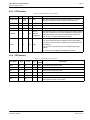
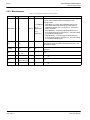
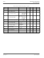
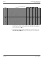
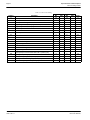
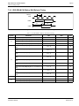
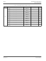
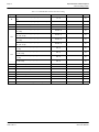
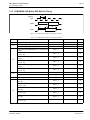
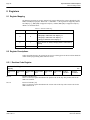
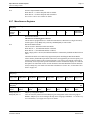
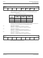
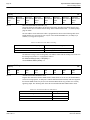
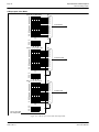
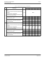
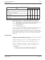
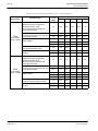
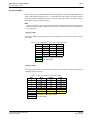
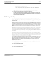
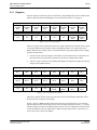
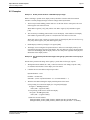
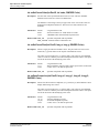
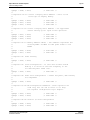
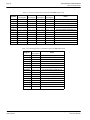
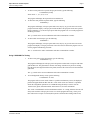
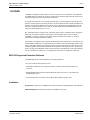
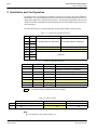
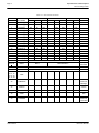
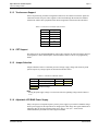
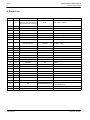
The image data for pixel n, (An,Bn), selects the color for pixel n as follows:
Table 12-2: Ink/Cursor Color Select
(An,Bn)
Color
Comments
00
Color 0
Ink/Cursor Color 0 Register, (REG[2Dh],REG[2Ch])
01
Color 1
Ink/Cursor Color 1 Register, (REG[2Fh],REG[2Eh])
10
Background
11
Inverted Background
Ink/Cursor is transparent – show background
Ink/Cursor is transparent – show inverted
background
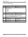
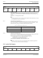
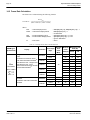
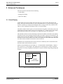
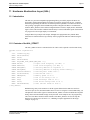
12.3 Ink/Cursor Image Manipulation
12.3.1 Ink Image
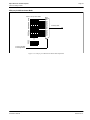
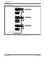
The Ink image should always start at the top left pixel, i.e. Cursor X Position and Cursor Y Position
registers should always be set to zero. The width and height of the ink image are automatically calculated to completely cover the display.
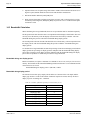
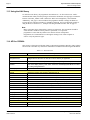
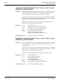
12.3.2 Cursor Image
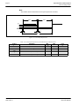
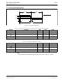
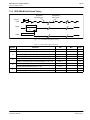
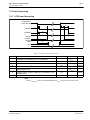
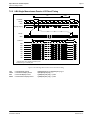
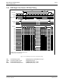
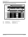
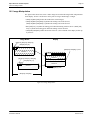
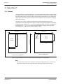
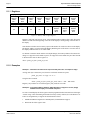
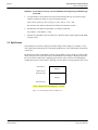
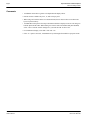
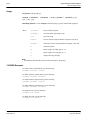
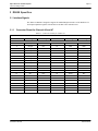
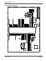
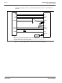
The Cursor image size is always 64x64 pixels. The Cursor X Position and Cursor Y Position
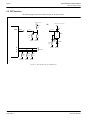
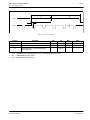
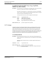
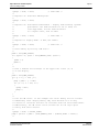
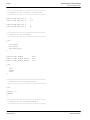
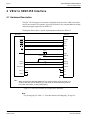
registers specify the position of the top left pixel. The following diagram shows how to position a
cursor.
P(0;0)
P(x;y)
P(x+63;y)
P(x;y+63)
P(x+63;y+63)
Figure 12-2: Cursor Positioning
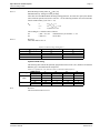
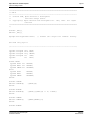
where
x = (REG[29h] bits [1:0], REG[28h])
y = (REG[2Bh] bits [1:0], REG[2Ah])
REG[29h] bit 7 = 0
REG[2Bh] bit 7 = 0
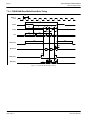
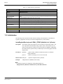
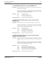
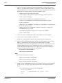
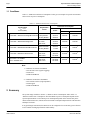
Note
There is no means to set a negative cursor position. If a cursor must be set to a negative position,
this must be dealt with through software.
Hardware Functional Specification
Issue Date: 99/05/18
SED1355
X23A-A-001-11