1
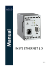
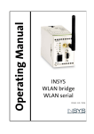
Operating Manual
INSYS GSM 4.1
Version 2.05 –02.04
Copyright © 2004 by INSYS MICROELECTRONICS GmbH
Any duplication of this manual as well as the enclosed software is prohibited. All rights
on this documentation and the devices are with INSYS MICROELECTRONICS GmbH Regensburg.
Restrictions of guarantee
This manual contains a concise description of the INSYS GSM 4.1. The compilation of the
text has been made with the utmost care. Despite all efforts, mistakes can never be prevented completely. No guarantee can therefore be given for the accuracy of the contents.
We can neither take over a legal responsibility nor any liability for wrong information
and their consequences. Suggestions for improvements and notification of errors are
gladly accepted.
Trademarks
The use of a trademark not shown below is not an indication, that it is freely available for
use.
MNP is a registered trademark of Microcom Inc.
IBM PC, AT, XT are registered trade marks of International Business Machine Corporation.
INSYS ® is a registered trademark of INSYS MICROELECTRONICS GmbH.
Windows™ is a registered trademark of Microsoft Corporation.
Publisher:
INSYS MICROELECTRONICS GmbH
Waffnergasse 8
93 047 Regensburg, Germany
Phone:
+49 (941) 560061
Fax:
+49 (941) 563471
[email protected]
E-mail:
Internet:
http://www.insys-tec.com
10. revised edition, Version 2.05 –02.04
Index
I
0
SCOPE OF DELIVERY
1
1
GENERAL
2
2
TECHNICAL DATA
4
2.1
GENERAL
4
2.1.1
Features
4
2.1.2
Data Services
4
2.1.3
Mechanical Features
5
2.2
SYSTEM REQUIREMENTS
5
2.3
INTERFACES AND DISPLAY ELEMENTS
5
2.3.1
Display Elements
6
2.3.2
Terminal Layout
7
2.3.3
Digital Inputs and Outputs
7
2.3.4
Power Supply
8
2.3.5
Serial Interface RS232 (V.24)
8
2.3.6
SIM Card
9
2.3.7
Audio Interface
9
2.3.8
Antenna Interface
10
2.3.9
Reset Button
10
2.4
APPROVALS / CE
10
3
INITIAL OPERATION
11
3.1
INSTALLATION OVERVIEW
11
3.2
INITIAL OPERATION
11
3.2.1
First Configuration by HSComm
12
3.2.2
First Configuration by Terminal Program
13
3.2.3
Restart
14
Version 2.05 –02.04
Index
II
3.2.4
Connection Test
14
3.3
TROUBLESHOOTING
14
3.3.1
Signal Quality
15
3.3.2
Log-In State in GSM Network
16
4
CONFIGURATION
17
4.1
CONFIGURATION SOFTWARE HSCOMM
17
4.1.1
Help
17
4.1.2
Menus
17
4.1.3
Status Bar
18
4.1.4
Buttons
18
4.1.5
Tabs
19
4.2
BASIC SETTINGS
19
4.2.1
GSM Connection
19
4.2.2
System Monitoring
24
4.2.3
Date/Time
24
4.2.4
Echo
24
4.2.5
Connection
25
4.2.6
Handshake
25
4.2.7
DTR
25
4.2.8
Serial Interface
25
4.3
ALARM
26
4.3.1
Alarm Trigger
26
4.3.2
Alarm Transmission Medium
27
4.3.3
Individual Message
28
4.3.4
Collective Message
28
4.3.5
Recipient Number
28
4.4
ADDITIONAL ALARM RECIPIENTS
29
4.5
SWITCH OUTPUT
30
Version 2.05 –02.04
Index
III
4.5.1
Activated by Command
30
4.5.2
Activated by State
30
4.6
ACCESS CONTROL
31
4.6.1
Selective Call Answer
31
4.6.2
Passwords, DTMF PIN
32
4.6.3
Security Callback
33
4.7
4.7 HISTORY
33
5
FUNCTIONAL DESCRIPTION
36
5.1
OPERATING MODES
36
5.1.1
Command Mode
36
5.1.2
Connection mode (online)
36
5.1.3
Alarm State
37
5.2
ALARM FUNCTIONALITY
38
5.2.1
Alarm Trigger
38
5.2.2
Alarm Actions
39
5.2.3
Main Recipient of an Alarm Message
39
5.2.4
Additional Recipients of an Alarm Message
40
5.2.5
Querying the Alarm Inputs
40
5.3
SWITCH OUTPUTS
41
5.4
SMS FUNCTIONS
41
5.4.1
Commands via SMS
41
5.4.2
SMS Acknowledgement
42
5.4.3
Creating and receiving an SMS
42
5.5
DTMF FUNCTIONS
43
5.6
LOGIN / LOGOUT
44
5.6.1
Automatic Login at Restart
44
5.6.2
Timer-Controlled Login / Logout
44
Version 2.05 –02.04
Index
IV
5.7
AUDIO INTERFACE / VOICE CONNECTIONS
44
5.8
FLASH UPDATE
45
5.9
OPERATION WITH PLC’S
45
6
AT COMMAND SETS
47
6.1
SHORT DESCRIPTION INSYS AT COMMANDS
47
6.2
COMPARISON IT COMMANDS / INSYS AT** COMMANDS
49
7
APPENDIX: GSM PROVIDER
51
7.1
SERVICE NUMBERS
51
7.2
SMS TRANSMISSION TO FAX AND E-MAIL
52
8
VERSION LISTS
53
9
CONFORMITY DECLARATIONS
54
Version 2.05 –02.04
0 Scope of Delivery
1
0 Scope of Delivery
Please check the scope of delivery before initial operation:
•
INSYS GSM 4.1
•
9-pin serial cable for connection between PC and INSYS GSM 4.1 (RS232 cable)
•
printed manual (German/English). The latest editions of the manual and the AT
command set are available for download at our internet site:
http://www.insys-tec.com/manual
If the content is not complete, please refer to your supplier.
Optional accessories:
•
GSM antenna (wall mounted antenna or magnetic foot antenna)
•
CD with configuration software HSComm (free) and manuals. The configuration
software is also available for download at our internet site:
http://www.insys-tec.com/configuration
Please check the device for shipping damage. Please refer to your supplier if damage exists.
Please keep the packaging material for dispatch or storage.
Version 2.05 –02.04
1 General
2
1 General
The INSYS GSM 4.1 is a terminal device according to ETSI GSM Phase 2/2+ for the transmission of data, voice, fax group 3 and SMS messages in 900 MHz and 1.800 MHz networks.
Design and interfaces
•
robust DIN rail housing
•
wide voltage range
•
5 Status LEDs (Power, Status, Connect, Rx/Tx, Signal)
•
serial interface via RS232 jack
•
screw terminals for supply, alarm inputs, switch output
•
connection for phone handset
•
control by AT commands:
•
locally (terminal)
•
remote (extended command set only)
•
by SMS (extended command set only)
•
integrated real time clock (RTC)
•
periodic alive SMS for operation monitoring
•
power up SMS after each power up (not reset)
•
flash update locally and remotely
•
event memory (history function) with 200 entries
Connection:
•
dualband GSM networks: Class 4 (2W @ 900MHz) , Class 1 (1W @ 1.800MHz)
•
automatic login into the network after power failures
•
periodical logout and login
•
extended data formats of the serial interface (10/11 bit)
Alarm input:
•
2 digital alarm inputs for monitoring
•
dispatch of alarm messages by SMS, fax, e-mail and via data connection or establishing a voice connection
•
dispatch of the alarm message to up to 10 further recipients out of a pool of 20
numbers
•
pulse input:
Version 2.05 –02.04
1 General
3
•
distinction of 10 pulse sequences per input
•
dispatch of an assigned message to an assigned number by SMS
•
dispatch of a message to additional numbers out of the number pool.
Switch output:
•
2 control relay outputs SPDT (single pole double throw)
•
control by
•
alarm input, RING, GSM network failure
•
AT command locally and remotely
•
SMS command
•
DTMF tone
Security and access protection
•
password protection for
•
incoming data connections
•
security callback
•
commands by SMS
•
output control by DTMF
•
remote configuration
•
selective call answer (CLIP)
•
PIN of the SIM card stored for automatic login
Version 2.05 –02.04
2 Technical Data
4
2 Technical Data
2.1 General
2.1.1 Features
•
mounting on DIN rail DIN EN 500 22
•
data, voice, fax, and SMS services (ETSI GSM phase 2/2+)
•
power supply 10..60 V DC, 50..80 V DC 5% ripple
•
level on V.24 interface according to V.28
•
V.24/V.28 interface with 9-pin SUB-D jack (screwed)
•
mini SIM card reader with integrated slot (3 V SIM card)
•
FME antenna connection
2.1.2 Data Services
Serial interface
•
interface terminal adapter (TA) – terminal equipment (TE)
•
compatible to RS232 (v.24/V.28)
•
baud rates: 300, 600, 1.200, 2.400, 4.800, 9.600, 14.400, 19.200, 28.800, 38.400,
57.600, 115.200 bps – standard: 19.200 bps
•
no automatic baud rate detection (command AT**BAUD)
Data connection:
Non-transparent asynchronous:
•
V.22bis (2.400 bps)
•
V.32/V.33/V.34 (4.800/9.600/14.400 bps)
•
V.110 (2.400/4.800/9.600/14.400 bps)
The support of particular data services in the GSM network depends on the GSM provider.
Version 2.05 –02.04
2 Technical Data
5
Fax transparent:
•
Group 3: Class 1 and Class 2
Voice connection:
•
HR/FR, EFR
2.1.3 Mechanical Features
Weight
270 g
Dimensions (maximum)
w x d x h = 55 x 110 x 75
Temperature range
0°C ..55°C
Protective class
housing IP 40/ screw termination IP 20
Humidity
0 - 95% non-condensing
Note: The INSYS GSM 4.1 must not be used in wet environments.
2.2 System Requirements
The INSYS GSM 4.1 is designed for the system environment of mobile networks with 900
MHz and 1.800 MHz corresponding to ETSI GSM phase 2/2+. The access to a GSM network requires a SIM card of the network provider (see chap. 777).
2.3 Interfaces and Display Elements
Front view
Version 2.05 –02.04
2 Technical Data
6
2.3.1 Display Elements
Name
Colour
On
Off
Power
green
Supply OK
No supply
Status
yellow
GSM engine
logged into
network*
GSM engine not
logged into network*
Connect yellow
Data connecNo data connection established tion established
Rx/Tx
green
Data exchange
over RS232
Signal
green
Best GSM signal GSM signal (field
(field strength) strength) too
low*
Blinking
Flashing
Data connection
periodic alive SMS,
Power Up SMS, and
SMS polling
alternate blinking with
LED Connect: Factory
settings loaded
alternate blinking with
LED Status: Factory settings loaded
No data exchange
Blinking interval depending on GSM signal (field
strength)*:
ON 25 .. 31
60 ms 23 .. 24
140 ms 21 .. 22
260 ms 19 .. 20
380 ms 17 .. 18
500 ms 15 .. 16
1000 ms 13 .. 14
OFF 0 .. 12, 99
For explanation of the
values see chap. 3.3.1
Blinking in intervals of 1
second during flash process
*)
periodical query of the login state and the GSM field strength has to be active (command
AT**GSMREQ)
Version 2.05 –02.04
2 Technical Data
7
2.3.2 Terminal Layout
Top
1
2
3
4
5
6
7
8
9
10
Terminal
GND
50..80VDC
10..60VDC
GND
GND
Reset
GND
Input 1
Input 2
GND
Ground
Supply 50V - 80V DC
Supply 10V -60V DC
Ground
Ground
Reset
Ground
Alarm input 1
Alarm input 2
Ground
Bottom
Terminal
11
OUT1NC
Output 1 – normally closed
12
OUT1COM
Output 1
13
OUT1NO
Output 1 – normally open
14
OUT2NC
Output 2 – normally closed
15
OUT2COM
Output 2
16
OUT2NO
Output 2 – normally open
2.3.3 Digital Inputs and Outputs
Alarm input
The alarm inputs are designed as pull-up and are on HIGH in inactive, open state. The
alarm inputs are activated by connecting to ground.
LOW active
0 .. 1 V
HIGH inactive 4 .. 12 V
The input current from LOW to internal +5V is typically 0.5 mA.
Switch output
The switch outputs are galvanic insulated relays SPDT (single pole double throw).
Maximum switch voltage:
30
V (DC) / 42 V (AC)
Maximum current load:
1
A (DC) / 0,5
A (AC)
Version 2.05 –02.04
2 Technical Data
8
2.3.4 Power Supply
Voltage:
10..60 V DC or 50..80 V DC (5% ripple)
Standby (logged in)
Connect
Unit
Power consumption
approx.
1,1
2,1
W
Current consumption at
10VDC
110
200
mA
Current consumption at
24VDC
45
85
mA
Current consumption at
36VDC
32
60
mA
This values have been measured at for a signal field strength of 16 (AT**SIGNAL?). The
current consumption and the power consumption may increase for poor network conditions.
These are time average values for the estimation of the current consumption. The power
supply unit should be able to supply up to 10 W for small periodes (577 µs) to ensure
proper operation.
2.3.5 Serial Interface RS232 (V.24)
Description of the signals on the 9-pin D-SUB connector on DCE side (INSYS GSM):
9-pin D-Sub DCE
Pin No.
Description
1
DCD
2
Function
CCITT
EIA
DIN
E/A DCE to
DTE
V-24
RS232
66020
Data Carrier Detect
109
CF
M5
O
RXD
Receive Data
104
BB
D2
O
3
TXD
Transmit Data
103
BA
D1
I
4
DTR
Data Terminal Ready
108
CD
S1
I
5
GND
Ground
102
AB
E2
6
DSR
Data set ready
107
CC
M1
O
7
RTS
Request to send
105
CA
S2
I
8
CTS
Clear to send
106
CB
M2
O
9
RI
Ring Indication
125
CE
M3
O
Version 2.05 –02.04
2 Technical Data
9
2.3.6 SIM Card
The INSYS GSM 4.1 requires a SIM card from a GSM provider . The SIM card is the identification towards the network provider.
The slot for the SIM card is on the front of the INSYS GSM 4.1. Push the sunk yellow button above the card slot to unlock and pull out the insert. The visible contacts of the SIM
card must face the top, when inserting the SIM card into the holder. Push the card holder
back into the card reader (contacts of the SIM card to the left), until the card holder is
flush with the housing (see figure in chap. 3.2.3).
Notes:
Only 3V cards may be used.
Change the SIM card only when the device is switched off.
The GSM provider has to enable the desired services for the SIM card. A card can be enabled for voice and data services at the same time. The following cards and contracts are
normally available:
Function
Prepaid card
Contract for voice
transmission
Contract for data
transmission
Outgoing data connection
9
9
9
Incoming data connection
-
-
9
SMS
9
9
9
Voice connection
9
9
-
Note:
Different phone numbers are generally assigned to the different services
(voice, data connections with 2.400, 4.800 and 9.600 bps). The GSM network
does not connect a data call to a phone number for voice connections e.g.
2.3.7 Audio Interface
The INSYS GSM 4.1 has a 4-pin western jack at the front for a phone handset.
Pin layout of the western jack
Pin Usage
1
Microphone (-)
2
Speaker (-)
3
Speaker (+)
4
Microphone (+)
Reference type: Handset Siemens Gigaset
Version 2.05 –02.04
2 Technical Data
10
2.3.8 Antenna Interface
The antenna connector at the front of the INSYS GSM 4.1 is of type FME (male).
All commercial GSM antennas with a female FME connector can be used. Ensure that the
frequency band corresponds with the one of the provider when using single band antennas (900 MHz or 1800 MHz).
2.3.9 Reset Button
The INSYS GSM 4.1 re-initializes after a reset. This takes approximately 30 seconds and is
indicated by the flashing LED Status (see initial operation, chap. 3.2).
All data and voice connections are interrupted.
Reset
The device is reset to initial state by pressing the reset button shortly.
Factory settings
The device is reset to the factory settings for the extended AT commands by pressing the
reset button for more than 25 seconds. This corresponds to the command
AT**DEFAULT. The reset button can be released as soon as the LED’s Connect and
Status blink alternately. The device executes a restart. If the pin of the SIM card has
been saved, it is kept.
2.4 Approvals / CE
The INSYS GSM 4.1 bears the CE symbol of conformity. This symbol declares, that the
INSYS GSM 4.1 is designed in compliance with the currently valid versions of the following EC directives:
Directives:
89/336/EEC
73/23/EEC
91/263/EEC
Standards:
ETS 300 342 1
EN 60950
EN 55022
EN 55024
EN 300 607-1
EN 301 419-1
EN 3015011 V7.01
TBR 19, TBR 20
Approvals:
(EMC directive)
(low voltage directive)
(telecommunications devices directive)
(class B)
CE
Version 2.05 –02.04
3 Initial Operation
11
3 Initial Operation
3.1 Installation Overview
The serial interfaces (RS 232) of the INSYS GSM and the configuration PC are connected
for the initial operation and configuration. For the data communication during operation, the application (e.g. an SPS) is connected to the serial interface of the INSYS GSM
(dashed line), instead of the PC. The configuration of the digital inputs and outputs is
described in chap. 4.3
3.2 Initial Operation
The initial operation may take place comfortably by the configuration software HSComm
(see chap. 4) under Windows as well as directly by entering the AT commands by a terminal program (e.g. ProComPlus, HyperTerminal, terminal window of HSComm).
Carry out the following steps 1 to 4, 5a to 9a (HSComm) or 5b to 9b (terminal), and 10 to
13:
1. Have SIM card (see chap. 7777) and PIN number ready, but do not insert them.
2. Connect INSYS GSM and PC with serial cable. Connect GSM antenna.
3. Connect power supply to terminals 10..60 VDC or 50..80 VDC and negative pole to
GND and switch on. See chap. 2.3.4 for the requirements – Attention: the given
values are maximum values.
Version 2.05 –02.04
3 Initial Operation
12
4. Initialization starts:
• LED Connect is on for approx. 4 seconds
• 8 seconds later the LED Status starts to flash for approximately 20 seconds
• LED Status turn off afterwards, because no SIM card is inserted and no PIN is
entered.
• The LED Signal is on or blinks depending on the strength of the GSM network.
Continue either with the steps 5a to 9a with the configuration software HSComm or
with the steps 5b to 9b with a terminal program. Subsequently insert the SIM card and
execute a restart according to steps 10 to 13.
3.2.1 First Configuration by HSComm
Attention: The AT command sets of the current INSYS GSM 4.x and the prior version INSYS
GSM 2.0 are not identical:
Î Use HSComm GSM version 4.0.0.0 or higher for INSYS GSM 4.1
Î Use HSComm GSM version 2.0.6.1 for INSYS GSM 2.0
Alternative: For direct configuration by AT commands from a terminal program see the
steps 5b to 9b in chap. 3.2.2.
5a. Start HSComm under Windows:
6a. Select the following standard setting for the serial interface of the configurations
in the menu Interface:
7a. If the INSYS GSM is in an undefined state, reset it to the factory settings first (button Send default settings). If the INSYS GSM does not respond to the transmission
of commands, select the button Synchronize RS232 to adapt baud rate and data
format automatically.
Version 2.05 –02.04
3 Initial Operation
13
8a. Enter the PIN number (will be stored in the INSYS GSM): Select the tab Basic Settings, select new PIN and enter the PIN belonging to the SIM card. The PIN is stored
in the INSYS GSM and used for logging into the GSM network at every restart.
Transfer settings by activating the button Send settings.
9a. Check the field strength of the GSM signal using the button detect GSM intensity.
The response should be a field strength of at least 12 – otherwise, the antenna location has to be changed. (see also chap. 3.3.1)
3.2.2 First Configuration by Terminal Program
Alternative: For configuration by the configuration software HSComm under Windows
see the steps 5a to 9a in chap. 3.2.1.
5b. Start your terminal program or the terminal window of HSComm.
6b. Set the serial interface settings to the standard values: 19.200 baud, 8 data bits, 1
stop bit, no parity
Version 2.05 –02.04
3 Initial Operation
14
7b. If the INSYS GSM is in an undefined state, reset it to the factory settings first.
AT&F&WZ<CR>
AT**DEFAULT<CR>
8b. Store the PIN number (in the example below 1234 – to be replaced by your PIN)
for the SIM card by the following command and <CR> (Enter or Return key):
AT**PIN=1234<CR>
If the PIN of the SIM card is deactivated, enter AT**PIN=<CR> only.
9b. Check the field strength of the GSM signal:
AT**SIGNAL?<CR>
The response should be a field strength of at least 12 – otherwise, the antenna location has to be changed. (see also chap. 3.3.1)
3.2.3 Restart
10. Disconnect the power supply.
11. Press the sunk yellow button (see image) above the SIM
card slot and take out the card holder. Put the SIM card
into the card holder and insert it again. The contacts of
the SIM card face to the left when inserting.
12. Connect the power supply.
13. The initialization process starts again (see point 4): If the
device has logged in successful, the LED’s Power and
Status are on afterwards and the LED Signal indicates
the strength of the GSM signal.
3.2.4 Connection Test
After this first configuration, you can simply check whether your INSYS GSM 4.1 is connected with the GSM network:
Dial from the terminal window of the HSComm or your terminal program a phone number (e.g. your mobile phone) with the command ATD followed by the number and if it
rings, you see that it tries to establish a connection.
Attention: Make sure that your SIM card is enabled for incoming data connection if required (see chap. 2.3.62.3.6222222).
3.3 Troubleshooting
No response on commands
• INSYS GSM 4.1 and the terminal device (configuration PC or PLC) have to operate the
serial interface with the same baud rate and the same data format (Default: 19.200
bps, 8N1).
Version 2.05 –02.04
3 Initial Operation
15
• the INSYS GSM 4.1 can be reset to the factory settings by pressing the reset button
long (> 25 seconds) (see chap. 2.3.9)
No connection
• sufficient signal quality of the GSM network: see chap. 3.3.1
• INSYS GSM logged in: see chap. 3.3.2
• SIM card enabled for data connections: see chap. 2.3.6
• phone number for data (not voice) connection dialed: see chap. 2.3.6
• sufficient power supply for sending: see chap. 2.3.4
Alarm SMS is not dispatched
• SMSC entered correctly: see chap. 4.2.1
• deactivate DTR drop if no device is connected via the serial interface: see chap. 4.2.8 or
if a device is used that does not support DTR.
• deactivate handshake if no device is connected via the serial interface: see chap. 4.2.7
or if a device is used that does not support hardware handshake.
3.3.1 Signal Quality
The signal quality at the reception location is queried by the button detect GSM intensity
at the tab Basic settings or by the AT command AT**SIGNAL?. The response should be
more than 12 (maximum is 31). If required change the antenna location. The response 99
indicates that no field strength can be detected (e.g. due to network failure, defective
antenna).
The signal quality is indicated with an update interval of 1 minute (in idle state) by the
LED Signal:
LED Signal
Response of AT**SIGNAL?
always on
25 .. 31
60 ms
23 .. 24
140 ms
21 .. 22
260 ms
19 .. 20
380 ms
17 .. 18
500 ms
15 .. 16
1000 ms
13 .. 14
always off
0 .. 12
99
Version 2.05 –02.04
Quality of the radio link
optimum
very good
good
sufficient
not sufficient Î improve location
not detectable
3 Initial Operation
16
3.3.2 Log-In State in GSM Network
Check whether your SIM card and the entered PIN have been accepted by the command
AT+CREG?<CR> in the terminal window. The status, in the form <+CREG: 0,3> is indicated by the 2nd parameter of the response (in the example: 3, refused).
0
not logged in, no GSM network search
1
logged in at standard provider
2
not logged in, GSM network search
3
refused
5
logged in, roaming
If you are not logged in, check whether the device expects a PIN by the command
AT+CPIN?<CR> in the terminal window. The responses mean:
READY
no more input required
SIM PIN Enter PIN of the SIM card Î store the PIN for automatic login by the
INSYS GSM 4.1 (see chap. 4.2.1) and execute a reset.
SIM PUK Enter PUK of the SIM card Î a wrong PIN has been entered repeatedly
and is locked now. The PUK, which you find in the contract documents of
your GSM provider is needed to unlock. Remove the SIM card and enter
the PUK using the menu of any mobile phone. Absolutely ensure afterwards that the correct PIN is stored in the INSYS GSM.
Version 2.05 –02.04
4 Configuration
17
4 Configuration
4.1 Configuration Software HSComm
The software HSComm allows the configuration of the INSYS GSM 4.1 under Windows
without knowledge of the AT commands and their parameters. The settings are sent to
or read from the INSYS GSM only upon instruction (buttons Send settings or Read
settings).
The configuration software HSComm is available for free download in the internet
http://www.insys-tec.com/configuration
Attention: The AT command sets of the current INSYS GSM 4.x and the prior version INSYS
GSM 2.x are not identical:
Î Use HSComm GSM version 4.0.0.0 or higher for INSYS GSM 4.1
Î Use HSComm GSM version 2.0.6.1 for INSYS GSM 2.x
4.1.1 Help
The context sensitive is available by the key F1 or the menu Help.
The help also contains the complete command reference for the extended INSYS AT
commands.
4.1.2 Menus
File
The current settings, as displayed in the HSComm user interface, can be saved as a file
and read out again.
Interface
Setting of the serial interface by the configuration PC. The
baud rate and the format (data bits, stop bit, parity) have
to match the settings of the serial interface at the INSYS
GSM (see chap. 4.2.8).
Error
If the configuration was not successful plain text messages are displayed.
Version 2.05 –02.04
4 Configuration
18
Language
Selection of the HSComm user interface language: German or English. The setting does
not effect the functionality of the INSYS GSM 4.1
PLC
Recommended settings and explanations for the use of the INSYS GSM with the PLCs of
leading manufacturers. The INSYS GSM is typically used as communication device at the
PLC. The settings can be adapted to own requirements.
These settings are only transmitted by pressing the button configure modem at PC side /
configure GSM device at PLC side at this page.
Overview
All current settings of the HSComm are displayed. The output extends over several
screen pages and can be saved as text file.
Note:
Read out the settings of your device and have this overview ready before
contacting the hotline!
4.1.3 Status Bar
The status bar at the lower window border of the HSComm displays the setting and activities of the serial interface. RX and TX light up synchronous when receiving and sending data.
4.1.4 Buttons
Send settings
The current settings in the HSComm are transferred to the INSYS GSM
4.1.
The settings in the PLC window are only transferred on hitting the
button configure modem/GSM at PLC side.
Read settings
The current settings of the INSYS GSM 4.1 are read out and displayed in the HSComm.
Version 2.05 –02.04
4 Configuration
19
Send default settings
The factory default settings are loaded and a reset is executed. The device logs in into the
GSM network again afterwards if the PIN is stored.
Reset
Software reset of the INSYS GSM 4.1. The device logs in into the GSM network again if
the PIN is stored.
Synchronize
The serial interface of the INSYS GSM 4.1 and the connected device have to be configured
equally. All possible settings of baud rates and data format at the PC side are tested until
both sides match.
Abort
Terminates an ongoing configuration process (Send settings, Read settings, Send default
settings – indicated by the progress bar above the buttons).
4.1.5 Tabs
Basic and extended settings are spread across several pages, which can be selected by
the tab titles. The settings are transmitted to the INSYS GSM 4.1 only after pressing the
button Send settings.
The functions are described in detail in the following chapters.
4.2 Basic Settings
4.2.1 GSM Connection
PIN
The INSYS GSM 4.1 can store the PIN of the SIM card internally and logs into the GSM
network automatically when starting up.
To enter, activate new PIN and enter the PIN. Instead of the digits, only * are displayed.
The default setting is “0000”. If the INSYS GSM 4.1 has stored a PIN, the option PIN active
is checked.
A PIN stored in the INSYS GSM 4.1 is deleted by delete PIN. This also enables the operation
of SIM cards without PIN.
Version 2.05 –02.04
4 Configuration
20
PIN active indicates that a PIN is stored. The login state is indicated below:
GSM: registered
ready for operation
GSM: rejected
GSM network does not allow access
GSM: not registered
SIM accepted but no access to GSM network
GSM: network search
Radio contact with GSM network too poor Î relocate antenna
position
PIN missing
Enter PIN number of the SIM card and restart device
PUK required
PIN of the SIM card is locked after repeated false attempts. The
PUK, which you find in the contract documents of your GSM
provider, is required to unlock. Remove the SIM card and insert
it into a mobile phone where you can find a menu for unlocking the SIM card. Absolutely ensure afterwards that the correct
PIN is stored in the INSYS GSM.
Service Center Number
The number of the SMS service center (SMSC) of the own GSM provider is required for
sending alarm messages by SMS. Enter the number in international format (e.g. Germany: +49).
The SMSC for your SIM card is found by in the contract documents of your GSM provider.
Usual SMSCs are listed in Chap. 7.
Version 2.05 –02.04
4 Configuration
21
Idle connection control
Hanging connections, over which no data is exchanged anymore, can be terminated
automatically by the INSYS GSM after a waiting period.
Waiting period is entered in seconds, after which the data connection is terminated
automatically. Each character which is sent over the serial interface (both directions) retriggers the timer.
0
deactivated
1..255
activated
Automatic SMS processing
Incoming SMS messages are read out once per minute. Each SMS is checked for usability
(configurations, query alarm input, setting switch output) and possible validity (format,
password, selective call acceptance). A response SMS is sent after processing, if requested and the SMS is deleted from the storage location.
If the SMS is not usable, it will be deleted from the SMS buffer immediately.
SMS reception by the user application is only possible with restriction. The GSM engine is
operated in the mode AT+CMGF=1 (SMS text mode).
If the dialog box ′leave remote SMS in SIM buffer′ is activated (operating mode
AT**SMSRX=2), the SMS unknown to the controller are left in the SMS buffer and may
be used for the application.
Any activity at the serial interface (AT commands) restarts the query interval without
executing the query. No query is made during an active data connection.
During the query of the SMS, the LED Status is flashing. Commands entered at the serial interface are ignored. The query duration depends on the baud rate and the size of
the SMS storage to be queried.
Incoming SMS messages are protected by the remote configuration password if set (see
chap. 4.6).
Caution:
Keep the following in mind when using the option "leave unknown SMS in SIM card
memory":
1. The SMSs that are not processes by INSYS GSM 4.1, remain in the memory of the
SIM card until they are queried and deleted over the serial line. No more SMSs are
accepted while the SIM card memory is full.
2. The INSYS GSM 4.1 processed and deletes the following SMSs:
a) all SMSs with a valid configuration password (see chap. 5.3) if this is set,
regardless whether the subsequent command is valid or not.
b) all SMSs with a valid syntax if the configuration password is not set. That
are:
•
SMSs starting with AT**
Version 2.05 –02.04
4 Configuration
22
•
SMSs which consist of the text “QUITT”
•
SMSs which consist of an alarm message configured in the device (acknowledgement of alarms)
Possible solution:
The application should know the configuration password. In that case the application
can leave SMSs with this password at the INSYS GSM 4.1 and process and delete all other
SMSs.
Additionally, the polling cycle of the application should be longer than the controller’s
polling cycle (e.g. multiplier 2-3), as the controller triggers its polling cycle with every
query from application (= activity on RS232 interface). If not considering this, the controller can not query the SMS buffers any more.
SMS memory size
The number of SMS stored on the SIM card is read out by the button ‘get SMS-memory
spaces’.
The INSYS GSM 4.1 queries the SMS memory in intervals of one minute. The baud rate
and the number of SMS storage locations to be configured determine the duration of the
query.
Examples: Baud rate
19200
Configured SMS storage locations 15
Query duration
5 seconds
The number of SMS storage locations which should be considered by the controller during its query routine must be specified in the dialog box ‘configured SMS memory spaces’.
A problem may occur if there are more incoming SMS than SMS storage locations are
queried. In this case, SMS are stored in the storage location which is not considered by
the query and can therefore not be processed by the controller.
DTMF processing
The INSYS GSM 4.1 is ready to detect and process incoming DTMF tones during a voice
connection. (The number for voice connection has to be dialed.)
The following extended responses are displayed instead of RING when activated DTMF
processing activated:
+CRING: VOICE
for voice/DTMF connections
+CRING: REL ASYNC
for data connections
The DTMF functions are optionally protected by the DTMF PIN (see chap. 4.6).
Connection retries
The number of attempts to connect if the remote terminal does not answer. This setting
is effective for:
•
Dispatch of messages (alarm or periodic alive SMS)
Version 2.05 –02.04
4 Configuration
•
Connection for alarm messages via a data connection
•
Connection for security callback
23
Possible values are 1 .. 12, default is 3.
There are not retries for an acknowledgement SMS after a configuration by SMS.
Auto answer
A data call is accepted by the INSYS GSM 4.1 after this number of ring indications. (Incoming voice calls are automatically accepted with enabled DTMF processing.)
0
off
2..255
on
Version 2.05 –02.04
24
4 Configuration
Detect GSM intensity
The currently field
strength of the
GSM signal is read
out and displayed
graphically. Values
below 12 are poor
– the antenna location should be improved. The value 99 stands for not ascertainable
field strength, e.g. for network loss or damaged antenna. When the location of the antenna is changed, it usually takes 5 to 10 seconds until the field strength of the INSYS
GSM 4.1 is displayed correctly.
4.2.2 System Monitoring
Scheduled Logout/Login
The INSYS GSM 4.1 logs out for a short period and logs in again daily to allow maintenance functions of the GSM provider. Enter the logout time and the duration (1 to 98
minutes).
Subsequently, the INSYS GSM logs in into the GSM network again, if the PIN of the SIM
card is stored.
Scheduled Logout/Login with Reset
For scheduled logout/login with reset, a device reset can be performed during the scheduled logout.
Subsequently, the INSYS GSM logs in into the GSM network again, if the PIN of the SIM
card is stored.
Periodic alive message by SMS
The INSYS GSM can send a periodic alive message as SMS message daily, weekly or
monthly. The LED Status is flashing during the dispatch.
Power up SMS
If this function is active, a SMS is sent with each power up (not reset).
4.2.3 Date/Time
Setting date and time of the real time clock of the INSYS GSM 4.1 manually or according
to the system time of the configuration PC.
4.2.4 Echo
With echo, all commands which are transmitted to the INSYS GSM 4.1 via the serial interface are returned at the serial interface to allow local monitoring of the AT commands in
terminal operation.
Version 2.05 –02.04
4 Configuration
25
4.2.5 Connection
For a data connection with a device outside the GSM network (analog modem or ISDN
TA) the right protocol has to be selected. This setting is for data connections with a GSM
device.
4.2.6 Handshake
The handshake controls the data flow at the serial interface if the data rate is too high.
Software handshake controls the data flow by control characters (XON/XOFF) via the
data lines, hardware handshake uses separate control lines RTS/CTS.
Without handshake, overflowing data is ignored.
Attention:
Handshake must be deactivated, if the INSYS GSM 4.1 is operated
standalone – i.e. without connection via the serial interface – or if it is
operated with a device which does not support hardware handshake.
4.2.7 DTR
The control line DTR of the serial interface indicates whether a device (configuration PC,
PLC) is connected to the INSYS GSM and active. The setting controls the behavior when
the DTR signal is missing, e.g. when the terminal device (PC, PLC) is disconnected.
Attention:
Reaction on DTR has to be inactive, if the INSYS GSM 4.1 is operated
standalone – i.e. without connection via the serial interface – or if it is
operated with a device which does not support DTR.
4.2.8 Serial Interface
Settings of the serial interface of the INSYS GSM 4.1. The baud rate and the format (data
bits, stop bit, parity) have to match with the settings of the serial interface at the connected device.
AT commands
AT&D
function type of the control line DTR
AT**ALIVE
periodic alive SMS
AT**BAUD
baud rate of the serial interface
AT**DATE
date
AT**DAY
weekday
AT**DIAL
dial-up attempts for periodic alive or alarm messages
AT**DTC
Idle connection control (Data Transmit Controller)
Version 2.05 –02.04
4 Configuration
26
AT commands
AT**DTMF
enable DTMF processing
AT**FORMAT
data format of the serial interface
AT**GSMREQ
periodical query of the field strength and the login state in the GSM network
AT**LOGOUT
timer-controlled logout / login again or device reset respectively
AT**PIN
PIN of the SIM card
AT**POWER
dispatch of SMS during power up
AT**SCN
SMS service center number
AT**SIGNAL
GSM signal field strength
AT**SMSBUF
specification of existing SMS storage locations of the SIM card
AT**SMSRX
automatic SMS reception processing
AT**TIME
time
AT\Q
data flow control of the serial interface
ATE
set command echo
ATS0
automatic call acceptance
4.3 Alarm
The INSYS GSM 4.1 has two independent digital inputs for alarm detection. Alarms are
triggered by connecting an alarm input to ground. The alarm input is on HIGH potential
by a pull-up resistor in open state.
In case of an alarm, an alarm message can be dispatched or the switch output (see chap.
5.3 can be activated.
4.3.1 Alarm Trigger
Single alarms are triggered by connecting the input to ground.
The INSYS GSM 4.1 can distinguish pulse sequences from 1 to 10 pulses as pulse counter
and assign these to 10 different alarms. The pulses and pauses can have a length from
0,3 to 2 seconds.
Version 2.05 –02.04
4 Configuration
27
4.3.2 Alarm Transmission Medium
SMS: Dispatch of an SMS to the entered phone number. For pulse input, the message
text and the recipient number are used according to the number of pulses.
If the GSM provider supports these features, an SMS can also be sent to a fax device or an e-mail address.
For fax dispatch, enter the fax prefix of your GSM provider before the actual fax
number (examples see Chap. 7).
For the e-mail dispatch, send the SMS to the mail gateway of your GSM provider
(examples see chap. 7) and start the SMS text with the e-mail address of the recipient, followed by one space character and the message.
Many network providers transmit SMS messages to fixed network numbers as
voice messages.
Data connection short: A data connection will be established and the message will be
transmitted as plain text. After this, the connection will be terminated.
Data connection long: A data connection will be established and the message will be
transmitted as plain text. The connection remains until the alarm input is
deactivated. The connection can also be terminated by idle connection control
(Chapter 4.2.1), if the remote terminal hangs up, by DTR drop or +++ATH.
Voice: A voice connection is established and is maintained as long as the alarm input is
active. The connection for a handset is on the front (chap. 2.3.7)
Version 2.05 –02.04
4 Configuration
28
4.3.3 Individual Message
Alarm message – for pulse alarms 10 different texts according to the number of pulses.
The internal GSM character set does not match the usual ASCII character set of PCs in all
positions. Therefore, the following restrictions must be observed for SMS texts.
•
Permitted text characters in SMS messages are only letters (without umlauts),
digits, punctuation marks, brackets, underscore, % & *.
•
8-bit characters (e.g. umlauts) and the characters $ @ { } [ ] ^ ° ` ´ are not supported.
•
For e-mail addresses, the character @ must be replaced by the character *; KPN in
The Netherlands requires replacement by!.
•
When the underscore is entered in the terminal instead of the data entry mask of
the HSComm software, it must be replaced by the character 11h. The character
00h may not be used in any case.
4.3.4 Collective Message
All alarm messages start with this text, the message text according to the number of
pulses will be added. Collective message and individual messages may both have a
length of up to 140 characters – but only the first 140 characters of the composed message will be transmitted.
4.3.5 Recipient Number
Phone number of the recipient.
Data connection: GSM, ISDN or modem number
SMS:
Mobile phone or fixed network number*, fax prefix*+fax number,
mail gateway* (*support of the GSM provider required, see chap. 7)
Voice:
Mobile phone or fixed network number
10 further recipients from the number pool (see chap. 4.4) can be assigned to each alarm.
If further recipients are activated, the symbol
ber.
is displayed besides the phone num-
AT commands
AT**INPUT
configuration of the alarm inputs
AT**MSG
alarm message texts
AT**DST
main target number for alarm messages
AT**SMS
manual SMS dispatch of the stored alarm messages
Version 2.05 –02.04
4 Configuration
29
4.4 Additional Alarm Recipients
Each alarm, which is sent by SMS or short data connection, can be transmitted to 10 further recipients out of the number pool (see chap. 0). The number pool consists of 20 recipient numbers.
The additional recipients (in lines) are combined with the available alarm messages (in
columns).
A maximum of 10 additional recipients can be assigned to each alarm message.
The button delete all connections deletes all entered combinations.
AT commands
AT**COMBINE
combination of the alarm text with a target number from the number pool
AT**POOL
phone number pool for alarm messages
Version 2.05 –02.04
4 Configuration
30
4.5 Switch Output
The INSYS GSM 4.1 provides two relay switches, which can be switched by command or
by the device status. The settings for the two switch outputs are independent of each
other.
4.5.1 Activated by Command
If activated by AT command, SMS or DTMF is selected the
other options (4.5.2) can not be selected anymore. The
operation of the switch output is described in chap. 4.3.
The processing of SMS messages and DTMF tones has to be
enabled under Basic Settings (see chap. 4.2.1).
4.5.2 Activated by State
Following options can be selected only when activation by
AT command, SMS or DTMF is not enabled (4.5.1). The
switch outputs are switched to normally closed and updated when the next event occurs accordingly. The switch
output becomes active (normally open) as soon as one of
the following states occurs:
Alarm at alarm input
The switch output will be activated during the processing of alarm functions (alarm input 1 Æ switch output 1, alarm input 2 Æ switch output 2). With this, a signal can be
sent to an external device that the alarm input is busy.
Incoming call (RING)
An incoming RING signal switches the switch output active. With this, an external signal
(lamp, horn) can be switched.
GSM network loss
When the GSM network fails, the output is switched. Updated like LED Status after 60
seconds of inactivity of the serial interface.
Requirement: AT**GSMREQ=1
AT commands
AT**OUTPUT
configuration of the switch outputs
AT**OUT
manual switching of the outputs
Version 2.05 –02.04
4 Configuration
31
4.6 Access Control
4.6.1 Selective Call Answer
If this option is selected, only connections are accepted from the entered phone numbers. The caller has to activate the calling line identification presentation (CLIP). The selective call acceptance is also valid for data and voice connections as well as incoming
SMS commands (see chap. 5.4.1).
Incoming calls of numbers which are not allowed are rejected immediately. They can neither be accepted manually (ATA). The caller receives the signal BUSY.
Selective call acceptance is active after a device reset only. The GSM engine works with
the setting AT+CLIP=1. In addition, the phone numbers of incoming calls are displayed:
RING
+CLIP: "+49941560061",145,,,,0
The allowed number has to be entered in exactly the same format as it is displayed
(without ””). The transmitted format of the number may depend on the provider – e.g.
the leading “+49” may be replaced by “0049”. It is absolutely recommended to verify the
number by a test call.
It is possible to allow whole blocks of numbers: The wildcard character „*“ replaces one
single digit.
Version 2.05 –02.04
4 Configuration
32
4.6.2 Passwords, DTMF PIN
Besides the PIN for the SIM card (see chap. 4.2.1), which controls the access to the GSM
network, the INSYS GSM 4.1 manages three other passwords/PIN’s to control the access:
data connection, security callback
This password protects
•
incoming data connections
•
security callback (see chap.4.6.3)
The password consists of a maximum of 16 characters.
If an incoming connection is accepted and established, after 2 seconds the caller is asked
to enter the password:
SECURITY CALLBACK:
(only when callback is active)
REMOTE PASSWORD:
If no valid password is entered within 60 seconds, the connection will be terminated. A
valid password is acknowledged by OK.
If no security callback number is set (see Chap. 4.6.3), the connection is released for data
transmission after 2 seconds.
If a security callback number has been set, the existing data connection will be terminated and a new connection to the security callback number will be established after 30
seconds. If this connection is established, the message CALLBACK IN PROGRESS is
transmitted after 2 seconds and after 2 more seconds the interface is released for data
transmission. If the remote terminal is busy, the dial-up will be repeated according to the
setting connection attempts.
The LED Status is flashing during the security callback process.
Remote configuration, control by SMS
This password protects
•
remote configuration via data connection
•
the acceptance of SMS messages to switch and query the inputs/outputs (see
Chap. 5.2.5)
•
the acceptance of SMS messages with extended AT** commands
The password consists of a maximum of 16 characters.
The remote configuration mode is initiated by the escape sequence (default ***) during a
data connection (see chap. 5.1.1).
Switching via DTMF
The DTMF PIN controls the access to switch and query the inputs/outputs by DTMF tones
during a voice connection. The DTMF PIN consists of 4 digits.
Version 2.05 –02.04
4 Configuration
33
4.6.3 Security Callback
If a number is entered, the data password is queried for all incoming calls and the connection is terminated then. If the password has been entered correctly, the INSYS GSM
4.1 establishes a data connection to the entered number subsequently.
The security callback number is independent of the number of the caller, which triggers
the security callback.
Outgoing calls from the INSYS GSM 4.1 are not affected.
AT commands
AT**PASS
password
AT**CLIP
selective Call Answer
AT**DIAL
connection attempts
AT**CALLBACK
target number security callback
4.7 History
The ring buffer always contains the last 200 entries. The buffer will be deleted when resetting to factory settings. The entries are displayed on 1 to 4 pages in chronological order.
ASCII export
The displayed data can be stored as text file. Have this data ready if you request technical
support.
Version 2.05 –02.04
4 Configuration
34
History
The current values from the internal history list are read out and displayed.
The INSYS GSM records the following events continuously in a ring buffer.
Cause
SYSTEM
SECURITY
Detail
Meaning
RTC ERROR
internal real time clock defective (time stamp empty)
RTC RESET
internal real time clock has been reset since the gold cap was discharged
(power reserve used up) time stamp: 00:00:00 01.01.03
GSM ERROR
instruction from controller to GSM engine could not be processed correctly
(e.g. AT command, dial-up, SMS dispatch…)
SIGNAL ERROR
field strength not ascertainable (AT**SIGNAL?: 99)
LOGOUT
GSM engine logged out (update interval like STATUS LED)
LOGIN
GSM engine logged in (update interval like STATUS LED)
REMOTE PARAM
remote configuration starts (*** detected)
ALIVE
alive SMS process starts
POWER UP
Power Up executed
RESET
Software/ Hardware reset
DPW ERROR
data password has been entered wrong or timeout
PPW ERROR
configuration password has been entered wrong or timeout
TPW ERROR
DTMF PIN has been entered wrong or timeout
CLIP ERROR
call with invalid (rejected) phone number (selective call answer)
SECURITY
CALLBACK
security callback process starts
Version 2.05 –02.04
4 Configuration
Cause
ALARM
35
Detail
Meaning
Start
alarm at alarm input detected
End
Alarm at alarm input processed
Quit
Acknowledgement of an alarm message
outgoing voice connections
incoming voice connections for activated DTMF processing
VOICE
DATA
SMS
DTMF
Start
number for outgoing calls
number for incoming calls for activated selective call acceptance
End
voice connection terminated
Start
data connection outgoing or incoming;
incoming number given when selective call acceptance activated
End
data connection terminated
Power up
Power Up SMS dispatched
PARAM
SMS for configuration has been received*
QUITT
SMS with the text QUITT has been received*
QUITT
SMS for acknowledging a configuration SMS has been sent*
PARAM
DTMF command has been detected
*) automatic SMS processing has to be activated.
The following columns of the history list are displayed additionally:
Dir
Direction of the recorded event: IN stands for incoming, OUT for outgoing calls and SMS
messages.
Number
The involved phone numbers, alarm inputs and number of pulses are recorded when applicable.
Time/Date
Time stamp of the internal clock
AT commands
AT**HISTORY
Version 2.05 –02.04
read out history list
36
5 Functional Description
5 Functional Description
5.1 Operating Modes
The INSYS GSM 4.1 provides the following three operating modes – the separate configuration mode of earlier versions has been dropped with the integration of the extended
INSYS-AT** commands.
5.1.1 Command Mode
Offline
The offline command mode is the state after switching on or resetting the INSYS GSM
4.1. The INSYS GSM 4.1 can be accessed by AT commands in the AT command mode.
Online
The INSYS GSM 4.1 can be switched to online command mode during a data connection
by the escape sequence <1 second pause>+++<1 second pause> via the serial interface.
AT commands can be entered 2 seconds after the response OK. The data connection remains established, but may be terminated by the command ATH. The INSYS GSM 4.1
switches back to connection mode by ATO.
Remote configuration
The INSYS GSM 4.1 can be switched to remote configuration mode during a data connection by the escape sequence <1 second pause>***<1 second pause> via the data connection from the remote terminal. The data connection persist while extended INSYS AT**
commands are processed. The INSYS GSM 4.1 switches back to connection mode by
AT**EXIT.
If configured, the remote configuration password is requested before switching to the
remote configuration mode.
SMS configuration
If the INSYS GSM 4.1 is in command mode (offline), it can also receive extended INSYS
AT** commands via SMS. Syntax see chap. 5.4.1
5.1.2 Connection mode (online)
In connection mode the asynchronous byte stream between the serial interface of the
INSYS GSM and the remote terminal is exchanged transparently. The INSYS GSM 4.1 can
change to command mode by the local escape sequence +++ as well as to remote configuration mode by the remote escape sequence *** during a data connection.
Version 2.05 –02.04
5 Functional Description
37
Connection
ATD015265241
Dial number to which a connection is to be set up (always with
dialing code). The phone number must be closed with a semicolon only for voice connections.
The cursor is displayed, as long as the other phone rings.
CONNECT 9600/RLP
The call has been accepted. The data is exchanged over the GSM
network.
+++
Changing from data mode to online AT command mode. The
connection still remains, but no characters are transmitted to
the other modem anymore.
ATH
Hang up (terminate connection)
ATO
Return to data mode.
NO CARRIER
The other party has terminated the connection.
Termination
Connections can be terminated as follows:
•
manually by the ATH command in online command mode
•
if the remote terminal hangs up
•
by the idle connection control (Data Transmit Controller)
•
by activating an alarm input
•
by DTR drop
5.1.3 Alarm State
As soon as an alarm input of the INSYS GSM 4.1 has been activated, data and voice connections are terminated. Incoming commands are ignored during the processing of the
alarm actions. If an input is activated while processing an alarm at the other input, the
second alarm state is saved and executed subsequently.
If a connection cannot be established, a re-dial is attempted after 1 minute until the defined maximum number of dial-up attempts is reached.
Version 2.05 –02.04
5 Functional Description
38
The LED Status is flashing during the (attempted) connection set-up.
AT commands
***
remote configuration mode
+++
switch to online command mode
ATD
dial
ATH
close a connection
AT**EXIT
leave the remote configuration mode
ATO
leave the online command mode
AT**PASSC
password for remote configuration
AT**ESC
escape character for remote command mode
5.2 Alarm Functionality
The INSYS GSM 4.1 has 2 independent alarm inputs, which are pulled to HIGH by pull-up
resistors in open (inactive) state. The alarm inputs are activated by connecting to ground.
5.2.1 Alarm Trigger
Each alarm input can be configured as single alarm input or as pulse input (see chap.
4.3.1).
Single alarm input
A single alarm is triggered by changing the alarm input
from HIGH to LOW/GND. The alarm is accepted after 0,3
seconds. Even in case it is configured as pulse input, a
single alarm is triggered as soon as the input is connected to ground for at least 4 seconds - irrespective of
the prior history.
Pulse input
Sequences of up to 10 pulses can be detected as different alarms at the pulse input. Pulses and pauses may
last from 0,3 to 2 seconds.
The pulse input can be used particularly to transmit
several alarm states from small PLCs like SIEMENS Logo!™, Crouzet Millenium™, Comat
BoxX™ or Moeller Easy™. A demonstration program for creating such pulse sequences
with the PLC “Siemens Logo” is available on request (e-mail to [email protected]).
Version 2.05 –02.04
5 Functional Description
39
5.2.2 Alarm Actions
When detecting an alarm state, the following actions can be configured (see chap. 4.3.1):
Alarm action
Single alarm
Pulse alarm
Set-up of a long data connection (remains established after transmitting the message as long as the alarm is active)
9
-
Set-up of a short data connection (will be terminated immediately
after transmitting the message)
9
9
Dispatch of an alarm message as SMS
9
9
Set-up of a voice connection
9
-
Switching the corresponding switch output
9
9
Requirements for sending an SMS are:
•
valid number of the SMS service center SMSC (see chap. 4.2.1)
•
valid recipient number
•
text of the alarm message is defined
•
existing connection with GSM network
•
DTR behavior and handshake deactivated if no device is connected via the serial
interface.
An existing data connection is terminated before an alarm message is dispatched via
SMS or data connection, or before a voice connection is established.
If no connection can be established, as much dial-up attempts will be made as configured under basic settings (chap. 4.2.1) in intervals of approx. 60 seconds.
The LED Status is flashing during the alarm processing.
5.2.3 Main Recipient of an Alarm Message
The following devices can be recipients of an alarm message:
•
mobile phone as SMS recipient in the GSM network or for voice connection
•
fax device (via SMS)
•
E-mail recipient in the internet (via SMS)
•
fixed network phone as SMS recipient (voice output by network provider) or for
voice connection
•
analog Modem, ISDN TA or GSM device for data connections
The SMS transmission to a fax device or an e-mail address requires the support by the
network provider (see Chap. 7). The voice output of SMS messages in the fixed network
has to be supported by the network provider as well.
Version 2.05 –02.04
5 Functional Description
40
5.2.4 Additional Recipients of an Alarm Message
Each alarm message, which is dispatched by SMS or short data connection, can be sent
additionally to 10 further recipients out of a pool of 20 numbers.
The alarm messages to these additional recipients are all transmitted in the same way
(via SMS or short data connection) as to the main recipient.
5.2.5 Querying the Alarm Inputs
The state of the alarm inputs can be queried via AT commands, SMS or DTMF:
AT command
Entering the command AT**IN? <CR> via a terminal program or the terminal window
of HSComm. The responses mean:
OPEN
not activated, open
CLOSE
activated, connected to ground
SMS query (see chap.5.4.1)
The automatic processing of SMS messages has to be enabled (see chap. 4.2.1)
DTMF query (see chap.5.5)
The processing of DTMF tones has to be enabled (see chap. 4.2.1)
AT commands
AT**MSG
alarm message texts
AT**DST
main target number for alarm messages
AT**DIAL
dial-up attempts for periodic alive or alarm messages
AT**SCN
SMS service center number
AT**COMBINE
combination of the alarm text with a target number out of the number pool
AT**POOL
phone number pool for alarm messages
AT**IN
query the alarm inputs
AT**INPUT
configuration of the alarm inputs
Version 2.05 –02.04
5 Functional Description
41
5.3 Switch Outputs
The INSYS GSM 4.1 provides two galvanic insulated relay switches (see Chap. 2.3.3),
which can be switched by command or by the device status. The two switch outputs can
be configured independently (see Chap.4.5).
AT command
Enter the command AT**OUT[<output>]=<status><CR> via a terminal program or
the terminal window of HSComm with the following parameters:
<output>
1, 2
Switch output OUT1 or OUT2
<status>
0
Switch output to normally close
1
Switch output to normally open
PULSE<xx> Switch output is pulsed <xx> times
<xx>
01 .. 10
Number of pulses (two-digit)
This command can also be entered in remote configuration mode via an existing data
connection (see chap.5.1.1).
SMS command (see chap. 5.4.1)
The automatic processing of SMS messages has to be enabled (see chap. 4.2.1)
DTMF query (see chap. 5.5)
The processing of DTMF tones must be enabled (see chap. 4.2.1)
AT commands
AT**OUT
set/query the switch outputs
AT**OUTPUT
Configuration of the switch outputs
5.4 SMS Functions
If automatic SMS processing is activated, incoming SMS messages are checked, as soon as
the INSYS GSM 4.1 is not busy with data connection, alarm processing and processing of
AT commands for 60 seconds. Incoming SMS messages are optionally password protected (see chap. 4.6.2).
5.4.1 Commands via SMS
Most of the extended AT** commands as well as commands for switching the outputs
and querying the alarm inputs can be transferred via SMS to the INSYS GSM 4.1. Responses can be sent back via SMS to a user defined number.
Version 2.05 –02.04
5 Functional Description
42
Syntax for extended AT commands via SMS:
[<password>,]<command>[,CN: <reply>]
<password> Password for remote configuration and SMS query. If no password is
set, the separating comma is dropped also.
<reply>
Optional phone number, to which the response is sent via SMS. The
number must be separated from “CN:” by a space.
<command>
Extended AT** command with parameters
Examples for switch outputs / alarm inputs:
<command>
AT**OUT1=OPEN
Switch output 1 to normally open
AT**OUT2=CLOSE
Switch output 2 to normally open
AT**OUT2=PULSE09
AT**IN?
Output 9 pulses at switch output 2
Query state of the alarm inputs
5.4.2 SMS Acknowledgement
An SMS in the format of a command SMS, which contains only the text QUITT instead of
an AT** command, is entered in to the history list, with time stamp and calling number
if automatic SMS processing is active.
An alarm message that is received as SMS may be acknowledged by sending it back to
the INSYS GSM 4.1.
5.4.3 Creating and receiving an SMS
The INSYS GSM 4.1 can create as well as receive SMS messages by AT commands. The
respective commands and parameters are listed in the separate document “AT Command Set for INSYS GSM 4.1” under http://www.insys-tec.com/manual.
Attention: If automatic SMS processing is activated, the SMS messages are read out,
processed and deleted once a minute by the INSYS GSM 4.1 (see Chap. 4.2.1).
AT commands
AT**SMSRX
automatic SMS reception processing
AT+CMGD
delete SMS message
AT+CMGF
SMS message format
AT+CMGL
list SMS message
AT+CMGR
read SMS message
AT+CMGS
send SMS message
Version 2.05 –02.04
5 Functional Description
43
AT commands
AT+CSCA
number of the SMS service center
AT^SMGL
list SMS messages (without changing the state)
AT^SMGO
SMS overflow
AT^SMGR
read SMS message (without changing the state)
5.5 DTMF Functions
DTMF tones (e.g. from a touch-tone phone) can be used via a voice connection to query
alarm inputs and to switch outputs. The INSYS GSM 4.1 has to be called using its voice
number.
These functions are optionally protected by a PIN (see chap. 4.6.2). If a PIN is set, the PIN
(4 digits) has to be entered first after the connection establishment. This is acknowledged with ERROR or OK.
The following commands (keys) are defined:
0*
Terminate connection
1*1
Switch output 1 to normally open
1*0
Switch output 1 to normally closed
2*1
Switch output 2 to normally open
2*0
Switch output 2 to normally closed
3*
Query the alarm inputs: response state input 1 – pause – state input
2
Each command is acknowledged by OK first. The acoustic responses have the following
meaning:
acoustic
corresponding keys
OK
low (short) high (short)
*#
ERROR
low (long)
1
Input inactive (HIGH)
high (medium long)
D
Input activated (LOW)
low (medium long)
1
The processing of DTMF tones has to be enabled (see chap. 4.2.1). Incoming voice calls
are automatically accepted if DTMF processing is enabled.
AT commands
AT**DTMF
Version 2.05 –02.04
enable DTMF processing
5 Functional Description
44
5.6 Login / Logout
5.6.1 Automatic Login at Restart
The PIN number has to be stored in the controller to allow the INSYS GSM to log in automatically after a restart/reset (see chap. 3.2, 4.2.1).
By default, the INSYS GSM 4.1 logs into the strongest GSM network at every restart or
reset. If required, a preferred network can be pre-selected with the command
AT**PROVIDER (syntax and parameters are listed in the separate document “AT Command Set For INSYS GSM 4.1” under http://www.insys-tec.com/manual).
SIM card change
Prior to changing a SIM card, the PIN must be changed or deleted before inserting a new
card. Otherwise, the INSYS GSM 4.1 will lock the SIM card after three login attempts.
5.6.2 Timer-Controlled Login / Logout
In order to allow changes in infrastructures and software updates by the network providers, the INSYS GSM 4.1 can log out daily at a given time. Subsequently, the device executes a reset or logs in again after a user defined pause. For settings see chap. 4.2.1. If an
alarm is activated during this pause at an external alarm input or a periodic alive SMS is
due, the module will login again immediately. If the logout time has not been expired,
the INSYS GSM 4.1 logs out again afterwards.
The logout procedure will be postponed during active data connections. A voice connection and a communication in AT command mode will be interrupted immediately when
logging out.
AT commands
AT**LOGOUT
time scheduled logout
5.7 Audio Interface / Voice Connections
The INSYS GSM 4.1 has a standard western jack at the front to connect a phone handset
of reference type Handset Siemens Gigaset (see chap. 2.3.7).
The connection is set-up and closed either by AT commands in the terminal program or
by an alarm input (Medium for alarm transport: voice see chap. 4.3.1).
AT commands
ATD<nr>;
set-up voice
ATH
terminate connection
ATA
accept call
Version 2.05 –02.04
5 Functional Description
45
5.8 Flash Update
The firmware of the INSYS GSM 4.1 can be loaded locally or using a data connection. The
firmware exists as file with the suffix MHX.
The terminal baud rate has to be set to 19.200 bps for the local flash process. The following responses are returned with this fixed baud rate.
Hardware handshake is absolutely necessary. For remote flash (using the data connection) it must be ensured that hardware handshake is activated for both the terminal program and the modem of the remote terminal. To avoid a remote flash crash, the GSM 4.1
baud rate must be set to 19,200 bps. In addition, the terminal program that initiates the
flash process must be set to a line delay of at least 100 ms (line end character TX=CR).
The duration of the remote flash is approx. 5 minutes.
AT**FLASH
Enter command in terminal window
Start Update with Esc, Reset with @
Flash process starts if the ESC key is
pressed within 60 seconds. This
prompt also appears for every restart
(with a timeout of 2 seconds).
Expecting download with 8N1
Prompt for sending
The firmware has to be sent as *.mhx file.
Settings of the terminal program:
Protocol:
ASCII
Data format:
8N1
Handshake:
Hardware
After the flash process is completed, a full device reset is executed.
If necessary for the adaptation, the settings are reset to factory settings. The PIN of the
SIM card is kept).
AT commands
AT**FLASH
firmware update
5.9 Operation with PLC’s
The INSYS GSM 4.1 has been tested for the most common PLC systems on the market.
The documentation of the settings required for the respective PLC can be queried at
INSYS (mailto: [email protected]).
Version 2.05 –02.04
5 Functional Description
46
Currently, documentations for the following PLC systems are available:
•
Bosch SPS CL400
•
Mitsubishi MELSEC FX 2N / 232BD
•
OMRON SPS C200HX – CPU44
•
PILZ SPS PSS3056
•
Schiele SPS S400
•
Siemens S7/200
•
Systron S200, S250 and S400
Version 2.05 –02.04
6 AT Command Sets
47
6 AT Command Sets
The INSYS GSM 4.1 is configured and controlled using two AT command sets: The standard AT commands control the GSM engine to establish data connections using the GSM
network. The extended INSYS AT** commands control the extensions implemented by
INSYS for the digital inputs/outputs, alarm functions, security functions and timercontrolled functions.
The standard AT commands can be entered locally via the serial interface if the device is
either in offline state (no active data connection) or in online command mode
(interrupted data connection).
The extended INSYS AT** commands can be entered locally as well as remotely (remote
configuration) and in most cases also by SMS. The configuration by SMS is restricted to
commands with responses of up to 140 characters.
The most important standard AT commands and all extended AT commands are listed in
the document “AT Command Set For INSYS GSM 4.1” which is available from INSYS
MICROELECTRONICS (e-mail to [email protected]) and at the internet site
http://www.insys-tec.com/manual. The complete command reference for the standard
AT commands is also available on request.
The modem guideline V.25 ter is applicable with respects to the time sequence of
commands. The AT standard is a line-oriented command language. The commands are
not context-sensitive. All commands are closed with the carriage return character set
with the command ATS3 (default = <CR> = 0x0D).
Note:
Lining up several commands per input line is not possible for the extended
INSYS AT commands. Further commands can be sent only after the processing
of the previous command, i.e. when the response has been output.
For lining up standard AT commands please refer to the detailed command set of the
GSM engine.
The IT commands implemented in INSYS GSM 2.0 are replaced by the extended INSYS
AT** commands of the form AT**name, changing to configuration mode is not necessary anymore. A replacement table for the IT commands can be found in chap. 6.2.
6.1 Short Description INSYS AT Commands
Command
Configuration
Short description
Local remote SMS
AT**ALIVE
periodic alive SMS
X
X
S
AT**BAUD
baud rate of the serial interface
X
X
X
AT**CALLBACK
target number security callback
X
X
X
AT**CLIP
selective call acceptance
X
X
S
Version 2.05 –02.04
6 AT Command Sets
48
Command
Configuration
Short description
Local remote SMS
AT**COMBINE
combination of the alarm text with a target number from
the number pool (AT**POOL)
X
X
S
AT**DATE
date
X
X
X
AT**DAY
weekday
X
X
X
AT**DEFAULT
factory settings of the INSYS AT** commands
X
X
X
AT**DIAL
dial-up attempts for periodic alive or alarm messages
X
X
X
AT**DST
main target number for alarm messages
X
X
S
AT**DTC
idle connection control (Data Transmit Controller)
X
X
X
AT**DTMF
enable DTMF processing
X
X
X
AT**ESC
escape character for remote command mode
X
X
X
AT**EXIT
exiting the remote command mode
AT**FLASH
firmware update of the controller
X
X
AT**FORMAT
data format of the serial interface
X
X
X
AT**GSMREQ
periodical query of the field strength and the login state in
the GSM network
X
X
X
AT**HISTORY
history function (event memory)
X
X
S
AT**IN
querying the alarm inputs
X
X
X
AT**INPUT
configuration of the alarm inputs
X
X
X
AT**LOGOUT
timer-controlled logout / login again or device reset respectively
X
X
X
AT**MSG
alarm message texts
X
X
S
AT**OUT
set/reset the switch outputs
X
X
X
AT**OUTPUT
configuration of the switch outputs
X
X
X
AT**PASS
Password Protection
X
X
X
AT**PIN
PIN of the SIM card
X
X
X
AT**POOL
phone number pool for alarm messages
X
X
S
AT**POWER
dispatch of SMS during power up
X
X
X
AT**PROFILE
query of the settings of the INSYS AT** commands
X
X
X
Version 2.05 –02.04
6 AT Command Sets
Command
49
Configuration
Short description
Local remote SMS
AT**PROVIDER
manual GSM provider selection
X
X
X
AT**RESET
device reset
X
X
X
AT**SCN
SMS service center number
X
X
X
AT**SIGNAL
GSM signal field strength
X
X
X
AT**SMS
manual SMS dispatch of the stored alarm messages
X
AT**SMSRX
automatic SMS reception processing
X
X
X
AT**SMSBUF
specification of existing SMS storage locations on the SIM
card
X
X
X
AT**TIME
time
X
X
X
AT**VERSION
query of the software version
X
X
X
X = completely implemented
X
S = only setting implemented
6.2 Comparison IT Commands / INSYS AT** Commands
The IT commands implemented in INSYS GSM 2.0 are replaced by the extended INSYS
AT** commands of the form AT**name, changing to configuration mode is not necessary anymore.
IT command
INSYS AT** command
new
ITA
AT**OUTPUT
AT**INPUT
configuration of outputs
configuration of inputs
ITA*
AT**OUT
switching also possible by local command
ITAS
AT**OUTPUT
AT**SMSRX
automatic SMS reception processing has to be enabled with
AT**SMSRX
ITB
AT**BAUD
common baud rate for controller and GSM engine
ITD
AT**DST
ITDC
AT**CALLBACK
ITE
not applicable
standard AT command ATE
ITF
AT**FORMAT
common data format for controller and GSM engine
Version 2.05 –02.04
6 AT Command Sets
50
IT command
INSYS AT** command
new
ITI
AT**IN
query also locally
ITM
AT**DATE
AT**DAY
New: weekday with AT**DAY
ITN
AT**MSG
ITO
AT**LOGOUT
additional device reset possible
ITP
AT**PIN
4 to 8 digit PIN possible
ITR
AT**PROFILE
ITS
AT**SCN
ITT
AT**TIME
ITU
AT**PROVIDER
ITV
AT**DIAL
ITW
AT**PASS
ITX
AT**EXIT
ITY
AT**SMS
ITZ
AT**RESET
extended (with seconds)
Version 2.05 –02.04
7 Appendix: GSM Provider
51
7 Appendix: GSM Provider
In the following you find an overview about the most important mobile providers in
Germany, Austria, and Switzerland (state 2002). No responsibility is accepted for the correctness and completeness of this information. The given numbers may only be valid for
particular contracts with the network provider.
Please find the current data for your SIM card in your contract documents.
7.1 Service Numbers
Country
Provider
Network
SMS Service Center
Number (SCN)
Fax Prefix
Number of the
E-Mail Gateway
D
T-Mobile
T-D1
+49 171 076 0000
+49 171 209 2522
99 (German)
98 (English)
8000
D
Vodafone D2
D2 Vodafone
+49 172 227 0000
+49 172 227 0042
+49 172 227 0111
+49 172 227 0010
+49 172 227 0222
+49 172 227 0333
99
3400
D
E-Plus
E-Plus
+49 177 061 0000
+49 177 060 0000
+49 177 062 0000
1551
767 62 45
D
O2
O2
+49 176 0000 443
+49 176 0000 433
329
6245
D
Mobilcom
D1
+49 171 076 0315
1091
1090
D
Mobilcom
D2
+49 172 0227 0880
1091
D
Mobilcom
E-Plus
+49 177 061 0000
1551
A
Mobilkom
A1
+43 334 0501
+43 664 0501
-
-
A
max.mobil
+43 676 021
6762
6761
A
One (Connect)
+43 699 000 1999
-
-
CH
Orange
Orange
+41 78 777 7070
CH
Swisscom
Swiss GSM
+41 79 499 900 0
+41 79 499 812 3
CH
TDC
Sunrise
+41 76 598 0000
Version 2.05 –02.04
7 Appendix: GSM Provider
52
7.2 SMS transmission to Fax and e-mail
An SMS can also be sent to a fax device or an e-mail address with support of the GSM
provider.
Examples:
In order to transmit a message via SMS from the T-D1 network to the fax number
0123/456789 select the following settings:
SMS service center:
+491710760000
Phone number:
990123456789 (the leading + is replaced with 00 in international phone numbers)
Message:
140 characters
In order to transmit a message via SMS from the Vodafone network to the e-mail
recipient [email protected] select the following settings:
SMS service center:
+491722270000
Phone number:
3400
Message:
name*domain.de remaining text
E-mail address and remaining text must be separated by a
space
The @-sign must be replaced by an asterisk *.
Version 2.05 –02.04
8 Version lists
53
8 Version lists
Firmware
Version:
Description
1.1
Basic version
1.21
New:
•
Power up SMS
•
AT**SMSBUF
•
AT**SMSRX=2
Changes:
•
The history currently has 200 entries
•
non-authorized callers are immediately rejected
Hardware
Version:
Description
INSYS GSM 4.0
GSM Engine TC35
INSYS GPRS 4.0
GSM/GPRS Engine MC35
INSYS GSM 4.1
GSM Engine TC35i
INSYS GPRS 4.1
GSM/GPRS Engine MC35i
Version 2.05 –02.04
54
9 Conformity Declarations
9 Conformity Declarations
Version 2.05 –02.04
55
Version 2.05 –02.04