1
GDAŃSK
integra_i_e 05/05
Firmware Version 1.00
Alarm Control Panels
INSTALLER
MANUAL
WARNINGS
For safety reasons, the alarm system should only be installed by qualified personnel.
In order to avoid the risk of electric shock, read carefully this manual before proceeding to
installation. Any connections should only be made in deenergized state, i.e. with power
supply disconnected.
The control panel should be connected to PSTN (analog) lines only. Connecting the
telephone circuit directly to digital network (e.g. ISDN) will cause damage to the equipment.
The alarm system may comprise dangerous devices, therefore it is necessary that its
components be kept so as to prevent unauthorized access to the equipment.
If the service operations consist in fuse replacement, they must only be carried out with
supply voltage disconnected. Only fuses having identical parameters with the original ones
can be used for the replacement.
It is recommended that the manufacturer’s prescribed housings and power supply units be
used.
Making any construction changes or unauthorized repairs is prohibited. This applies, in
particular, to modification of assemblies and components.
CAUTION!
It is impermissible to connect a fully discharged battery (with voltage on unloaded terminals
less than 11V) to the alarm panel. In order to avoid equipment damage, the fully discharged /
never used battery should be precharged by means of a suitable charger.
The batteries used in the alarm systems contain lead. When used-up, the batteries must not
be thrown away, but disposed of as required by the existing regulations (European Directives
91/157/EEC and 83/86/EEC).
DECLARATION OF CONFORMITY
Products:
CA424P, CA832, CA16128P - main
Manufacturer: SATEL spółka z o.o.
boards of INTEGRA control panels.
ul. Schuberta 79
- INTEGRA 24
80-172 Gdańsk, POLAND
- INTEGRA 32
tel. (+48 58) 320-94-00
- INTEGRA 64
fax. (+48 58) 320-94-01
- INTEGRA 128
Product description: Main boards for alarm control panels intended for use in intruder alarm systems.
These products are in conformity with the following EU Directives:
LVD 73/23/EEC+93/68/EEC
EMC 89/336/EWG + 91/263/EEC, 92/31EEC, 93/68/EEC
R&TTE 1999/5/EC (network connection, TBR21)
The product meets the requirements of harmonized standards:
LVD: EN 50131-1:1997; EN 50131-6:1997; EN60950:2000, EN60335-1:1994/A1:1996 Annex B
EMC: EN 55022:1998; EN 61000-3-2/-3; EN 50130-4:1995, EN 61000-4-2/-3/-4/-5/-6/-11
R&TTE: TBR 21(1998)
Head of Test Laboratory:
Gdańsk, Poland
07.03.2005
Michał Konarski
Latest EC declaration of conformity and product approval certificates are available for downloading on
our website www.satel.pl
CONTENTS
1. GENERAL .............................................................................................................................. 3
2. GENERAL FEATURES OF CONTROL PANELS .............................................................................. 3
3. SYSTEM COMPONENTS ........................................................................................................... 4
3.1
3.2
3.3
3.4
3.5
3.6
3.7
3.8
3.9
3.10
3.11
3.12
MAINBOARDS ............................................................................................................................... 4
INTEGRA LCD KEYPAD ............................................................................................................... 6
SYNOPTIC BOARD ......................................................................................................................... 6
INTEGRA PARTITION KEYPAD ...................................................................................................... 6
INTEGRA CODE LOCK ................................................................................................................. 7
EXPANDER FOR DALLAS CHIP READERS ...................................................................................... 7
ZONES EXPANDER ........................................................................................................................ 7
OUTPUTS EXPANDER .................................................................................................................... 7
ZONES EXPANDER WITH POWER SUPPLY UNIT ............................................................................... 7
OUTPUTS EXPANDER WITH POWER SUPPLY UNIT ........................................................................... 7
ADDRESSABLE ZONES EXPANDER ................................................................................................. 7
VOICE SYNTHESIZERS EXPANDER ................................................................................................. 8
4. FUNCTIONAL DESCRIPTION ..................................................................................................... 9
4.1 OBJECTS ..................................................................................................................................... 9
4.2 PARTITIONS ............................................................................................................................... 10
4.3 ZONES ....................................................................................................................................... 13
4.3.1
4.3.2
4.3.3
4.3.4
Identification and numbering of zones in the system ..........................................................................13
Parameters ..........................................................................................................................................14
Options.................................................................................................................................................15
Zone type.............................................................................................................................................16
4.4 OUTPUTS ................................................................................................................................... 19
4.4.1
4.4.2
4.4.3
4.4.4
4.4.5
4.5
4.6
4.7
4.8
4.9
Parameters ..........................................................................................................................................19
Options.................................................................................................................................................20
Source of output triggering ..................................................................................................................20
Clearance availability...........................................................................................................................21
Output types ........................................................................................................................................21
CODES AND USERS .................................................................................................................... 25
PREFIXES .................................................................................................................................. 25
MONITORING .............................................................................................................................. 26
MESSAGING ............................................................................................................................... 30
ANSWERING PHONE CALLS ......................................................................................................... 32
4.9.1 Control via telephone...........................................................................................................................32
4.10 CONTROL OF OUTPUTS FROM LCD KEYPAD................................................................................. 33
4.11 REMOTE CONTROL ..................................................................................................................... 33
4.12 CONTROL PANEL STARTER ......................................................................................................... 34
5. CONTROL PANEL INSTALLATION ............................................................................................. 35
5.1 CONNECTION OF POWER SUPPLY ................................................................................................ 38
5.1.1 Description of electric connections ......................................................................................................39
5.1.2 Control panel power supply starting procedure...................................................................................39
5.2
5.3
5.4
5.5
5.6
5.7
5.8
5.9
5.10
CONNECTING LCD KEYPADS ...................................................................................................... 40
CONNECTION OF EXPANSION MODULES ....................................................................................... 46
CONNECTION OF DETECTORS ..................................................................................................... 48
CONNECTION OF SIRENS ............................................................................................................ 50
CONNECTION OF TELEPHONE LINE .............................................................................................. 51
CONNECTION OF VOICE SYNTHESIZERS ....................................................................................... 52
CONNECTION OF PRINTER........................................................................................................... 52
CONNECTION OF SERVICE COMPUTER ......................................................................................... 53
CONNECTION OF EXTERNAL MODEM AND GSM-4 MODULE ........................................................... 54
6. STARTING THE CONTROL PANEL............................................................................................. 57
6.1 STARTING THE SYSTEM .............................................................................................................. 57
2
SATEL
INTEGRA
6.2 SERVICE MODE .......................................................................................................................... 58
6.2.1 Service mode menu .............................................................................................................................60
6.3 CONTROL PANEL PROGRAMMING ................................................................................................ 76
6.4 PROGRAMMING BY TELEPHONE .................................................................................................. 76
7. BASIC SPECIFICATIONS ......................................................................................................... 78
1. GENERAL
This manual has been prepared for the whole family of INTEGRA alarm control panels. As
a rule, the general information contained herein refers to the INTEGRA 128, which is the
biggest of them. During installation of the smaller control panels, it is necessary to make
allowance for differences in technical parameters which are characteristic of the particular
mainboards (see Table, page Błąd! Nie zdefiniowano zakładki.).
All parameters of the INTEGRA alarm system can be programmed both with the use of a PC
computer, as well as with an LCD keypad.
Detailed information about specifications of the alarm system software is contained in the
„Help” system of the DLOADX program purchased with the alarm control panel or available
at the website www.satel.pl. In order to make use of the system, install and run the program,
and then highlight the required element of the program window and press the F1 key on the
computer keyboard. Another way of getting access to the “Help” is by opening the
“Information” drop-down menu and selecting the “Help”.
2. GENERAL FEATURES OF CONTROL PANELS
The INTEGRA series alarm control panels are designed for small, medium-size and large
facilities. Irrespective of its dimensions, each of the control panels has identical, advanced
functional capabilities. The alarm systems which are based on them can be without difficulty
extended by using the same expansion modules for all these control panels. It also makes
possible to easily replace the control panel with a bigger one, if it is required by development
of the system. Owing to such a solution, the optimal control panel can be selected for the
particular site. The INTEGRA alarm control panels not only guarantee a perfect protection of
the facility against burglary; they also offer advanced functions of access control and
automatic operation of a number of devices. At the same time, they are easy to operate and
user-friendly.
The control panels are characterized by the following features:
• Processor system with software stored in the FLASH memory, which allows panel
firmware updating and adding new functions. New software versions can be loaded via the
control panel RS-232 port without removal of the panel from the site.
• Possibility to keep the parameters programmed by service personnel in the FLASH
memory. Thus, even on disconnecting the memory back-up battery, the control panel can
restore the previous settings.
• Possibility to divide the system into objects and 32 partitions (partition = group of zones).
The partitions may be controlled by the user, timers, control zones, or their status may be
dependent on the status of other partitions. It is possible to temporarily restrict the access
to partitions.
• Possibility of system development by adding the expansion modules (the development
extent depending on the control panel size). Creation of a system based on modules
(including the module of SATEL wireless detectors) installed at various places throughout
the facility can considerably reduce the amount of cabling used.
• Possibility to store in the system from 16 to 240 passwords (codes), which may be either
assigned to users or to control functions.
• Advanced functions of simultaneous system control by means of LCD keypads and user
computers connected to them. Additionally, the service personnel have an option to control
the panel either via the RS-232 port or through a telephone link. Individual partitions can
also be controlled through partition keypads assigned to them.
4
SATEL
INTEGRA
• Possibility to control the access to selected partitions of the facility by means of partition
keypads, code locks, proximity card readers and DALLAS chips, which enable monitoring
the access doors as well as controlling the locks (electric latches). The monitoring of door
status does not reduce the number of zones controlled by the panel.
• Possibility to define the names of users and of majority of system components (partitions,
zones, outputs, modules) which facilitates the control and monitoring of system as well as
viewing of events log.
• Monitoring is provided to four different telephone numbers (two stations, each with a backup number), with a possibility to divide events into 8 identifiers. Besides basic transmission
formats, the control panel makes possible monitoring in Ademco Contact ID format.
• Alarm messaging to telephones by means of voice messages or to a pager with SMS
messages. Reception of a message can be acknowledged with a code entered from the
telephone set keyboard (DTMF).
• Function of phone call answering, which enables checking the status of all control panel
partitions and controlling the status of outputs. It is performed after user identification
(each user may be assigned a special “telephone” password/code).
• Extended function of events printing, which enables the events to be sorted. Event
descriptions are in accordance with the events list in Ademco Contact ID format, hence the
printouts from the control panel correspond to those from the monitoring station. Besides,
the names of zones, modules and users are printed as they are defined in the system.
• Additional function of the control panel RS-232 port, i.e. controlling the external analog
modem, ISDN modem, GSM module, or ISDN module of SATEL manufacture, enables
communication to be established with the service computer. In this case, the remote
programming via telephone network as well as the service are as quick as direct
programming from the computer via RS-232 port.
• Possibility of time-based control owing to timers that operate on week work cycle, with an
option to define exception periods. Additionally, each partition is provided with its own
timer (based on week or day cycle), programmed by the suitably authorized user, to
secure automatic arming and disarming.
• Facilitated performance of non-standard functions due to a possibility to make complex
logic operations at outputs.
• High-capacity event log where, in addition to the monitored events, also other events (like
user access, functions used, etc.) are stored.
3. SYSTEM COMPONENTS
The control panels are provided with communication buses which enable modules to be
added in order to enhance hardware capabilities. This, along with the firmware up-dating
feature, which ensures new functionality, facilitates easy upgrading of the system. It allows
the system to be extended by new components which will be developed in future in order to
better meet the customer’s needs and requirements. The INTEGRA control panels are
capable of working together with the CA-64 panel dedicated modules, though some of them
have to be made with a new program version. The system can operated by means of
keypads designed for new alarm control panels.
Described below are the components that can be incorporated in the INTEGRA system.
3.1 MAINBOARDS
Show in the table below are technical parameters of the alarm systems based on particular
control panels of the INTEGRA family.
INTEGRA
Installer Manual
Technical parameter (quantity)
Zones, mainboard
Zones, system
High-current
outputs,
programmable,
mainboard
Dedicated power outputs for keypads,
expanders and detectors
Outputs, OC type, mainboard
Outputs, system
Connectors for voice synthesizers
Keypads, system
Expander buses
Expanders, system
Zone expanders
Output expanders
Objects
Partitions
Timers
Telephone numbers for messaging
Pager messages
Voice messages
Remote switches
Users (w/o master user and service)
Event log
Power supply capacity across terminals [A]
(for control panel with keypad connected)
Battery charging current [mA]
Current capacity, programmable outputs:
high-current / OC [A]
Current capacity, power-supply outputs:
+KPD / +EX1 with +EX2 [A]
+KPD / +EX / AUX [A]
5
INTEGRA INTEGRA INTEGRA INTEGRA
24
32
64
128
4
8
16
16
24
32
64
128
2
2
4
4
3
3
2
2
2
20+4*
1
4
1
32
2
2
1
4
16
4
16
16
16
16
899
6
32
1
4
1
32
3
3
4
16
32
8
32
16
16
64
899
12
64
2
8
2
64
6
6
8
32
64
16
64
16
16
192
6143
12
128
2
8
2
64
14
14
8
32
64
16
64
32
32
240
22527
1
1
2,5
2,5
350
350/700
500/1000
500/1000
2 / 0.05
2 / 0.05
3 / 0.05
3 / 0.05
2.5 / 2.5
-
2.5 / 2.5
-
0.5/0.5/0.5 0.5/0.5/0.5
* 20 physically available outputs (mainboard + expanders) + 4 virtual outputs (to perform logical functions – see
description of output types 46 and 47).
• Zones programmed individually to handle configurations with or without end-of-line resistor
(NO, NC, EOL, 2EOL/NO and 2EOL/NC) with functional test of the detector. One of a few
dozens of response types can be chosen for each zone.
• High-current outputs with electronic fuses and low-current outputs designed to control
relays, with a programmable operating mode and a possibility to select one of a few
dozens functions.
• High-current outputs with electronic fuses for “power supply output” function.
• 1 or 2 connectors for voice synthesizers (SM-2 or CA-64 SM).
• Communication bus (keypad bus) for connection of LCD keypads and synoptic board
module.
• 1 or 2 communication buses (expander buses) for connection of additional modules to
expand the mainboard functional capabilities. 32 or 64 such modules can be connected to
the control panel.
6
SATEL
INTEGRA
• Telephone communicator, provided with a DTMF detection system for reception of
commands via the telephone, as well as for monitoring, messaging, answering calls and
remote programming.
• RS-232 port enabling the alarm system operation by means of a computer (DLOADX
installer program), interfacing with a printer and the use of an external modem.
• Switching-mode power supply with short-circuit protection, provided with battery
monitoring and discharged battery disconnection circuit.
• Independent real time clock with calendar, provided with its own back-up battery.
• Visual signaling of operation of all outputs, battery charging circuit and telephone
communication unit.
• Protection of all zones, outputs and communication buses.
3.2 INTEGRA LCD KEYPAD
The INTEGRA keypads are made in two versions: with or without a built-in proximity card
reader. Both of them have the following features:
• Large, easy to read 2x16 characters display with permanent or temporary backlighting
activated on pressing a key or by any control panel zone.
• 17-key keyboard with backlighting controlled in the same way as the display backlighting.
• 2 zones with properties identical to main panel zones.
• Microswitch for keypad tamper detection.
• RS-232 port enabling the alarm system to be operated by means of computer (GUARDX
supervisory and user program – full monitoring of system status, virtual keypad, easier
management of users).
3.3 SYNOPTIC BOARD
The INTEGRA alarm control panels support synoptic boards with firmware in version
v4.0 or later.
• Visualization of the state of all partitions and 64 zones of the alarm system by means of
LEDs.
• Two optional operating modes:
− monitoring mode (with any number of boards connected)
− keypad mode (an option to define the way of LEDs blinking and a possibility to connect
a computer with GUARDX program to the RS-323 port).
• Switching-mode power supply with short-circuit protection.
• Battery charging and control system with disconnection of a discharged battery.
• Module tamper zone.
3.4 INTEGRA PARTITION KEYPAD
• 12-key keypad with permanent or temporary backlighting
• 3x2 LEDs (ALARM, ARMED, TROUBLE) showing the status of partition to which the
keypad is assigned.
• Microswitch for keypad tamper detection.
• Relay for control of electromagnetic latch, lock or interlock.
• NO/NC input for door status monitoring.
INTEGRA
Installer Manual
7
3.5 INTEGRA CODE LOCK
•
•
•
•
•
12-key keypad with permanent or temporary backlighting.
3x2 LEDs showing readiness, access allowed and, additionally, system trouble.
Microswitch for code lock tamper detection.
Relay for control of electromagnetic latch, lock or interlock.
NO/NC input for door status monitoring.
3.6 EXPANDER FOR DALLAS CHIP READERS
•
•
•
•
•
One or two reading heads (recording entry and exit),
Relay for electromagnetic door lock control,
Relay control input (NC),
Door status control input (NC),
Additional module tamper zone (NC).
3.7 ZONES EXPANDER
• 8 zones with properties identical to the main panel zones.
• Additional module tamper zone.
3.8 OUTPUTS EXPANDER
• 8 outputs with functional properties identical to the mainboard outputs in three versions:
8 relay outputs, 8 OC type outputs or 4 relay outputs/ 4 OC type outputs.
• Module tamper zone.
3.9 ZONES EXPANDER WITH POWER SUPPLY UNIT
•
•
•
•
8 zones with properties identical to the main panel zones.
Additional module tamper zone.
Switching-mode power supply, capacity 2.2A, with short circuit protection.
Battery charging and control circuit with discharged battery cut-off.
3.10 OUTPUTS EXPANDER WITH POWER SUPPLY UNIT
• 8 outputs with functional properties identical to the mainboard outputs in three versions:
8 relay outputs, 8 OC type outputs or 4 relay outputs/ 4 OC type outputs.
• Module tamper zone.
• Switching-mode power supply, capacity 2.2A, with short circuit protection.
• Battery charging and control circuit with discharged battery cut-off.
3.11 ADDRESSABLE ZONES EXPANDER
The INTEGRA control panels support addressable zones expanders having firmware in
version v1.5 or later.
• Bus (3 wires) for connecting up to 48 addressable modules operating with typical
detectors, mounted directly in the detector casing; the detector with addressable module
mounted inside it is referred to as ADDRESSABLE DETECTOR,
• Additional module tamper zone,
8
SATEL
• Switching-mode power supply, capacity 2.2A, with short circuit protection,
• Battery charging and control circuit with discharged battery cut-off.
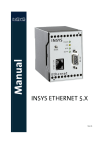
3.12 VOICE SYNTHESIZERS EXPANDER
• Memory module for storing 16 verbal messages, 15 seconds per each message.
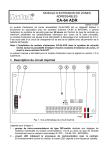
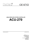
Exemplary devices interfacing with the INTEGRA alarm control panel
INTEGRA
INTEGRA
Installer Manual
9
4. FUNCTIONAL DESCRIPTION
This section presents basic information on the INTEGRA control panel features, as defined in
the firmware stored in FLASH memory. Views of the DLOADX program windows (version
1.00) are used in the system descriptions.
4.1 OBJECTS
Depending on its size, the INTEGRA control panel makes it possible to create 1, 4 or 8
objects. The objects are created in the service mode by using the „Edit object” function or the
DLOADX program. They are recognized as separate alarm systems. It is possible to
configure the control panel so that individual objects have their own separate controls (LCD
keypads, partition keypads, code locks) and signaling units, or, alternatively, they share the
equipment (LCD keypads and signaling units).
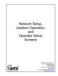
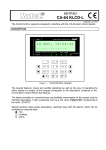
Fig. 1. System division into objects and partitions.
In the case of common LCD keypads, the controlled partition is recognized by the code of the
user who gives the command (i.e. the LCD keypad is not "assigned" to the object or partition.
Events from particular objects are sent to the monitoring station with individual identifiers.
After selecting the Ademco Contact ID format, the control panel sorts the events
automatically. For other formats, the events are assigned to identifiers by the installer,
according to the assignment of system components (zones, partition, users) to individual
objects.
10
SATEL
INTEGRA
4.2 PARTITIONS
The partition is a group of zones to supervise a selected part of the object, which are armed
or disarmed at the same time. The partition can only belong to one object. Division of the
object into partitions improves security of the object (some object partitions may be armed
while the others are still accessible to the users), and permits to restrict the users' access to
some parts of the facility. For example, in the facility shown in Figure 1, the workers of
Commercial Department (partition 3) will not be able to enter the book-keeping offices
(partition 2), unless they are granted authorization to arm / disarm the “Book-keeping”
partition.
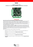
A partition can be created in the
service mode with the use of the
„Edit object” function, by assigning it
to the selected object. When
creating a partition, it can be given a
name (up to 16 characters). Also,
the partition type should be defined
(by default: Armed with code). The
function also removes partitions
from the given object.
The INTEGRA control panel makes
it possible to create the following
types of partitions:
• Armed with code – the basic
type of partition. Arming and
disarming is performed by the
user. Partition of this type is
provided with a timer of its own to
arm and/or disarm it, if it was not
done earlier by the user.
• With temporary blocking – it is
a version of the previous type of
partition. The difference is that at
the time of arming the control
panel asks to indicate the
blockage time period. Disarming
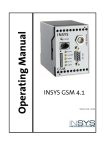
Fig. 2. Partition settings.
of this partition is only possible
after expiry of the blockage time. To disarm the partition before the blockage time is up
you have to use a code with „access to temporary blocked partitions” authority, or another
code, if an alarm occurred in that partition.
• Follow type ”AND” – the partition controlled by status
of other partitions. This partition is not armed directly by
the user, but automatically – when all partitions
indicated to the control panel become armed. The list of
partitions is defined by the service when creating the
dependent partition. The arming time is recorded in the
event log, with indication of the user who armed the last
partition from the list. When any partition from the list is
disarmed, the dependent partition will be disarmed as
Fig. 3. Definition of Follow type
well. Figure 3 shows the selection field of partitions that
”AND” partition.
control partition 3 (partitions 1 and 2 are selected, other
colors of background for partitions 3 and 4 show that partitions 3 and 4 cannot be selected
INTEGRA
Installer Manual
11
for controlling the dependent partition) For Follow type ”AND” partition no exit delay is
defined – the moment of switching over from “exit delay” to “armed” mode is set by the last
partition from the control list entering the armed status. The dependent partitions cannot
be controlled by timers.
Note: Follow type ”AND” partitions are normally used for protection of common corridors.
• Follow type “OR” – the partition becomes armed when any partition from the list of
control partitions becomes armed. The partition is disarmed at the moment when the last
partition from the list is disarmed. The exit delay time is the same as for the controlling
partition which causes arming of the Follow type “OR” partition”.
• Access according to timer – the partition is controlled by the user, but partition arming
and disarming is only possible within time periods determined by operation of selected
timers. Depending on the control panel size, an option with 16 or 32 timers is provided.
Beyond those time periods neither arming, nor disarming of the partition is possible. For
example, if the timer shown in Figure 4 is selected to control access to the “Secretary
office” partition, the partition arming / disarming will be possible according to schedule – on
Monday between 16:30 and 16:45, on Friday between 18:00 and 18:15 and so on, except
for the time periods given in the timer exception table.
Note: The „access to temporary blocked partitions” authority allows the user to freely control
the partition armed mode, irrespective of the timer status.
Fig. 4. Timing for Controlled by timer partition.
• Controlled by timer – the partition, which is armed in
time periods determined by selected timers, and may
also be controlled by the user code. When creating the
Controlled by timer partition, you should specify the list
of timers which set the periods when the partition is
armed. Depending on the control panel size, an option
with 16 or 32 timers is provided. The control panel
analyzes the status of timers selected, and, if any timer
status changes to “ON”, the control panel arms the
partition. Countdown of the exit delay time takes place
Fig.5. Selection of partition
before entering the full armed status. Disarming occurs
controlling timers.
when all the selected timers are “OFF”. The partition
can be also controlled by means of a separate “Partition user timer”, whose mode of
operation is programmable through the “Change option” user function. This timer controls
the partition in much the same way as the other timers. This method to control the partition
armed status is closely connected with the „Timer priority” option.
12
SATEL
INTEGRA
Note: When the partition is armed by the timer, the “Automatic arming” event is recorded.
The timer number is included in the event. The "0" number indicates that the user
timer armed the partition.
The following options and time settings can be programmed for the partition:
Arm by two codes - arming after two different codes authorized to control the partition are
entered in succession.
Disarm by two codes - disarming after two different codes authorized to control the partition
are entered in succession.
Codes on two keypads - enabling this option will prevent codes to be entered from the
same keypad (which applies to arming/disarming by means of two codes).
Timer priority - with this option selected, the timer will always perform arming and disarming
according to the preset times. With this option deselected, the disarming will only follow
if the arming is performed by timer - if the user sets armed mode with a code, the timer
will not disarm the partition.
EXAMPLE: If the partition is armed/disarmed by timer every day, and the user is leaving
and wants the armed mode to be on for a longer period of time - he will arm the partition
himself. With the "timer priority" option disabled, the timer will not disarm the partition at
the preset time and the user will not have to remember blocking the timer. When the
user comes back and disarms the partition by using the code, the automatic control of
the partition is restored according to the timer settings.
Partition user timer – see: Controlled by timer partition (for the DLOADX program the
function is only available during connection with the control panel).
Partition exit delay - countdown of the partition arming delay as from the moment of
entering the code or activating the timer to the actual arming of the partition.
Auto-arming delay - the time by which the timer will delay the automatic arming of
a partition. Countdown of this time may be indicated on the partition keypads, LCD
keypads and on the control panel outputs. Entering a value bigger than zero will enable
an additional menu, which makes it possible to delay auto-arming (by entering
a deferment time). During the auto-arming countdown it is possible to block the autoarming function (until the next auto-arming time) by entering zeros alone in the Defer
auto-arm user function. The delay countdown completed, the control panel begins the
countdown of the "partition exit time" (provided that it has been set).
Alarm verification time - if the partition contains zones with selected prealarm option, then
alarm on violation of such a zone will only be triggered if during the alarm verification
time another zone is violated.
Audible alarm after verification - with this option enabled there will be no audible signaling
of prealarm, i.e. violation of the zone with prealarm option "on" - the audible signaling
will only be triggered when another zone is violated during the alarm verification time.
Guard round (on armed) every – setting the maximum period of time that can elapse since
the last guard round when the partition is armed. If the time is exceeded, the control
panel will record the "no guard round" event.
Guard round (on disarmed) every – setting the maximum period of time that can elapse
since the last guard round when the partition is disarmed. If the time is exceeded, the
control panel will record the "no guard round" event.
Blocked for guard round
If the facility is watched by guards, the round monitoring and signaling of guard absence
at a specified time is possible (the guard enters his code from an LCD, partition keypad
or code lock; which is recorded in the event log). The related times are specified
separately for each partition; setting the “0” time will disable the monitoring function. It is
possible to differentiate monitoring times depending on whether the partition is armed or
INTEGRA
Installer Manual
13
not. When the partition round requires violation of detectors and the guard is not
authorized to switch the detectors off, it is possible to set the bypass time period, which
starts when the guard enters his code to make a round.
The partition can also be bypassed by entering the “Temporary partition bypassing” type
of code. The bypass time value is to be specified individually for particular codes.
Cash machine block delay
Cash machine block time
These times are to be programmed if the system supervises the cash machines
(dispensers) by means of the 24H CASH MACHINE zones. Just one cash machine may be
assigned to each partition. Access to the cash machine is possible after entering the
“Access to cash dispenser” type of code. Entering the code from a keypad will start the
“time to approach” the cash machine (24H CASH MACHINE zone is still armed), followed
by countdown of the bypass time (during the countdown the 24H CASH MACHINE zone is
bypassed).
4.3 ZONES
The zone in the alarm system is the interface of mainboard, LCD keypad or expansion
module. Two electrical wires, commonly known as the "line", which is terminated with an
alarm detector or another type of detector, are connected between the zone terminal and the
common ground. Besides the detector, the electric circuit may incorporate the EOL
parameter, i.e. a resistance which terminates the line. Depending on the detector
configuration, it can be a 2.2kΩ resistor or 2 resistors 1.1kΩ each).
4.3.1 IDENTIFICATION AND NUMBERING OF ZONES IN THE SYSTEM
The number of available (existing) zones is recognized by the control panel in the process of
expansion module identification. Therefore, prior to assignment of the zones to partitions, it is
necessary to:
• complete the whole system installation,
• perform identification of keypads, expanders and zones (using functions available from the
control panel LCD keypad in the service mode),
• when the control panel is programmed by means of computer - download the data from
the control panel to the computer,
• perform logical partitioning of the system (creating additional objects, assigning partitions
to the objects),
• assign zones to the created partitions.
Notes:
• After restart of the settings (also in a new control panel), most of the service mode
functions are not available until the control panel completes identification of hardware.
• The control panel will automatically assign numbers of the system zones to those of the
mainboard and expanders (see the „CA-64 E Zone Expander” manual). The sequence of
zone assignment depends on the addresses set at the expanders. The mainboard zones
always carry the initial numbers: depending on the board size, these can be numbers 1-4,
1-8 or 1-16.
• The expander of addressable zones at the INTEGRA control panels can be installed
together with other zone expanders. The identification process will assign to that
expander a number of zones being a multiple of 8, depending on the number of actually
connected addressable detectors which have an addressable module installed.
Identification of the addressable zones (e.g. after adding some zones into the system) is
carried out jointly with expander identification.
14
SATEL
INTEGRA
• On the LCD keypad, the expander addresses in the name programming function are given
in hexadecimal format in the following manner:
− addresses from 00 to 1F refer to the first expander bus (the numbering corresponds to
the addresses set at microswitches – default names: Expander 01 ... Expander 32)
− addresses from 20 to 3F refer to the second expander bus in the INTEGRA 64 and
INTEGRA 128 control panels (continuation of the first bus addresses calculated as:
microswitch setting +32 (20 in hexadecimal format) default names: Expander 33 ...
Expander 64.
• The same zone cannot be assigned to several partitions at the same time. However, it is
possible to create partitions dependent on the status of other selected system partitions.
4.3.2 PARAMETERS
Zone name - up to 16 characters
Assigned to partition
Panel reaction type (see: Zone types)
Alarm delay / Entry delay / Signaling delay / Surveillance time / Bypass time (parameter
name depends on the control panel reaction type)
Keypad number – refers to type 58 zones: TECHNICAL - DOOR BUTTON.
Arming mode - the following armed modes are to be selected for type 80 and 82 zones:
1 – normal armed mode;
2 – INTERIOR DELAYED zones (type 3 zones) will be bypassed, EXTERIOR (type 8 zones)
will trigger silent alarm, and the other ones - audible alarm;
3 – same as 2, but the DELAYED zones type 0, 1 and 2 will act as instant ones.
Detector configuration – configuration of the connected detector (NO, NC, EOL etc.). The
INTEGRA control panel enables lines terminated with any detectors to be connected to
the zones in the following configurations (see: „Connection of detectors” p. Błąd! Nie
zdefiniowano zakładki.):
NC (detector with normally closed output),
NO (detector with normally open output),
EOL (detector in configuration with end of line resistor),
2EOL/NO (NO type detector in configuration with double end of line resistor),
2EOL/NC (NC type detector in configuration with double end of line resistor).
Zone sensitivity - the necessary duration of the actual zone violation until it is recorded by
the control panel (typically approx. 0.5 sec., e.g. for the PANIC button a shorter time is
recommended).
Max. violation time / Max. door opening time – exceeding the maximum time of violation /
door opening is recognized by the control panel as a detector failure (e.g. damaging or
masking the detector) / door. The „0” value will deactivate the time control.
Max. no violation time - exceeding the maximum time of no violation is recognized by the
control panel as a detector failure (e.g. damaging or masking the detector). The „0”
value will deactivate the time control.
Comment – this field is intended for entering important information regarding the particular
zone. Length of the comment is limited to 256 characters.
INTEGRA
Installer Manual
15
Fig. 6. Details of zone settings.
4.3.3 OPTIONS
Power up delay - the zone will be bypassed for 120 sec. after power is switched on (which
prevents triggering alarms e.g. when starting the alarm control panel).
Priority - this option makes arming impossible, if the zone with activated option is violated
(e.g. in case when windows have been left open, etc.).
Note: Prior to arming it is possible to preview the names of violated zones for which the
„Priority” option has not been activated. To do so, select the „Zones bef. arm”
(ÆService mode ÆOptions ÆVarious options).
Disarm on violation – option for type 82 zone - consecutive violations of the zone alternately
arm / disarm the partition. If the option is not selected, zone violation will arm and end of
violation will disarm the partition.
Video On Disarmed - violation of the zone will activate the VIDEO ON DISARMED type output
(intended for starting cameras and video recorders).
Video On Armed - violation of the zone will activate the VIDEO ON ARMED type output
(intended for starting cameras and video recorders).
Disable bypass - the zone cannot be bypassed by the "zone bypass" user function.
Bypassed if no exit - the zone will be automatically bypassed, if during the zone exit delay
no zone of the ENTRY/EXIT or EXIT type is violated.
Alarm if armed – option available to type 64-79 zones, when the „No bypass in armed”
option is selected. Violation of the zone when the partition it belongs to is armed will
trigger an alarm (provided that the control panel has recorded the partition exit after
arming).
Auto Reset 3 - the zone will be automatically bypassed if 3 alarms have been triggered since
arming time.
Auto Reset 1 - the zone will be automatically bypassed if 1 alarm has been triggered since
arming time.
Clearing Autoreset - if this option is on, and the zone has Auto Reset 1 or Auto Reset 3
option on, the panel will automatically clear the bypass once every 24h, at midnight),
provided that the zone was bypassed as a result of an alarm.
16
SATEL
INTEGRA
Prealarm - zone with alarm verification.
Bell delay - the zone triggers alarm instantaneously (starts monitoring and telephone
messaging), but audible signaling will be delayed by the time set as the "entry delay".
Clear alarm – option available to zones type 81 and 82. Violation of the zone will clear alarm
in the partition, if it is currently indicated.
Abort delay - information on the zone violation will not be reported to the monitoring stations
if the violation occurred during the entry delay.
Partition temporary blocking – option for the zone type 84. Violation of the zone will block
the partition for the time of guard round.
Restore after bell - the zone violation end code will be reported to the monitoring station not
immediately but only after alarming is over.
Restore after disarm - the zone violation end code will be reported to the monitoring station
not immediately but only after the alarm is cleared and the zone is disarmed.
Alarm on Exit delay end - the zone will trigger alarm if at the moment of ending the exit
delay countdown it is in the state of violation (with this option disabled the alarm is
triggered only if the zone state changes from normal to violation - when armed).
Write violations to event log - option for the zones type 47: NO ALARM ACTION – each zone
violation will be recorded in the event log.
No bypass if armed – option for the type 64-79 zones. Violation of the zone when the
partition it belongs to is in armed mode will block no group of zones (provided that the
control panel has recorded the partition exit after arming).
Abort voice messaging – option for the zones type 81-83. Violation of the zone will cancel
the messaging, if it is currently ongoing.
Alarm on unbypass – the zone will trigger an alarm if it is violated after unbypassing, and
the partition is armed.
4.3.4 ZONE TYPE
0. ENTRY/EXIT - delayed zone combining two functions:
entry - violation of the zone starts entry delay counting in the partition and turns on
delay for the interior delayed zones; the entry time may be signaled on keypads;
exit - during the exit delay the panel keeps watching the zone for violation - in case of
no violation (the user has armed the zone but has not left the facility), the zones with the
"bypassed if no exit" option active will be bypassed.
1. ENTRY - see the ENTRY/EXIT zone.
2. DELAYED WITH DELAY SIGNALING – a delayed-action zone with optional signaling of delay
countdown in keypads.
3. INTERIOR DELAYED - conditionally delayed zone: delay is only activated when the ENTRY or
ENTRY/EXIT zone has been violated first.
4. PERIMETER - instantly armed zone, allowing no exit delay (total or partition).
5. INSTANT - instant zone, without additional functions.
6. EXIT - see the ENTRY/EXIT zone.
7. DAY/NIGHT - if disarmed, the zone will signal violation acoustically in keypads and on the
ALARM DAY type outputs (signaling for a time period preset for the given output); when
armed, the zone acts as the INSTANT zone.
8. EXTERIOR – a zone with alarm verification: violation of the zone will start counting the
observation time (programmed as the zone entry delay) - if a second violation takes
place during this time, an alarm will be triggered. The first violation may be signaled at
the ALARM DAY type output.
9. 24H TAMPER - permanently armed zone, intended for the tamper circuits.
INTEGRA
Installer Manual
17
10. 24H VIBRATION - 24h zone intended for working with vibration detectors: during arming
(from LCD keypad), an automatic test of these detectors is performed - prior to starting
the „exit delay” countdown, the VIBRATION DETECTORS TEST type output is activated and
countdown begins of testing time, during which all vibration type zones in the given
partition should be violated.
11. 24H CASH MACHINE - zone intended for protection of a cash machine (see: Partitions).
12. PANIC-AUDIBLE - permanently armed zone, intended for operating the panic buttons.
13. PANIC-SILENT - permanently armed zone; its violation starts reporting to the monitoring
station and activates the SILENT ALARM type outputs without activating the audible alarm
signaling.
14. MEDICAL - BUTTON
15. MEDICAL - REMOTE CONTROL - violation of the medical zones will trigger an alarm signaled
in keypads and on the SILENT ALARM type outputs. The zone names and the codes of
events from those zones are compatible with the Ademco Contact ID monitoring
standard.
16÷31 COUNTING L1÷16 – the counting zones will signal an alarm when the number of
violations counted during a specified time period exceeds the set value. The control
panel offers the possibility to program 16 different counters, which define how the
counting zones will operate. Several zones can be assigned to each counter, thus
creating a group of counting zones. Violations of the counting zones in armed mode can
be signaled at the ALARM DAY type output.
The following information should be specified for each group of counting zones
(counters):
• Max. value - number of zone violations which, if exceeded, will trigger the alarm,
• Counting time - the time in which violations are counted
• Counter type
- normal
- all violations of counter group zones are counted
- omits recurs:
consecutive violations of the same zone are not counted
(alarm will be triggered if the number of violations from different zones exceeds
the maximum value).
32. 24H FIRE
33. 24H FIRE – SMOKE
34. 24H FIRE – COMBUSTION
35. 24H FIRE – WATER FLOW (FIRE)
36. 24H FIRE – HEAT
37. 24H FIRE – BUTTON
38. 24H FIRE – DUCT
39. 24H FIRE – FLAME
All the fire zones (type 32÷39) trigger alarms signaled on the FIRE ALARM type outputs. They
differ in the alarm code being sent to the monitoring station in the Ademco Contact ID format.
The names of these zones are compatible with the names of event codes in the CID format.
The fire outputs (except for the 24H FIRE – BUTTON) can work with alarm verification.
40. 24H FIRE SUPERVISORY
41. 24H LOW WATER PRESSURE
42. 24H LOW CO2
43. 24H WATER GATE DETECTOR
44. 24H LOW WATER LEVEL
45. 24H PUMP ACTIVATED
18
SATEL
INTEGRA
46 24H PUMP FAILURE
47. NO ALARM ACTION - zone intended for activating the outputs (e.g. ZONE VIOLATION, READY
STATUS etc.). If the “Write violations to event log” option is activated for this zone, every
violation will be recorded in the event log.
48. 24H AUXILIARY – PROTECTION LOOP
49. 24H AUXILIARY - GAS DETECTOR
50. 24H AUXILIARY - REFRIGERATION
51 24H AUXILIARY - LOSS OF HEAT
52. 24H AUXILIARY - WATER LEAKAGE
53. 24H AUXILIARY - FOIL BREAK
54. 24H AUXILIARY - LOW BOTTLED GAS LEVEL
55. 24H AUXILIARY - HIGH TEMPERATURE
56. 24H AUXILIARY - LOW TEMPERATURE
The zone types from 40 to 56 (auxiliary) signal alarms on the TECHNICAL ALARM type outputs.
The names of zones and the codes of events from those zones are compatible with the
Ademco Contact ID monitoring standard.
57. TECHNICAL - DOOR OPEN - zone intended for supervising the status of the door defined as
Dependent door in the access control module (which controls the electromagnetic door
lock).
58. TECHNICAL - DOOR BUTTON - zone intended for opening the door controlled via a partition
keypad, code lock (or another access control module). The value of entry delay time
entered for such a zone means the address of a door control module (from 0 to 31 –
modules of bus 1, from 32 to 63 - modules of bus 2, 32 - address 00, 33 - address 01,
etc.). Violation of such a zone will switch over the selected module relay and open the
door (e.g. entering a room requires the access code to be entered from the keypad
installed outside the door, while for exiting it is enough to press the button situated at
the door inside the room).
59. TECHNICAL - AC LOSS - intended for control of devices working together with the alarm
control panel e.g. additional power supply units. Violation of this zone will trigger the
trouble alarm in the control panel.
60. TECHNICAL - BATTERY LOW - intended for the battery control in additional power supply
units working together with the control panel. Violation of this zone will trigger the
trouble alarm in the control panel.
61. TECHNICAL - GSM LINK TROUBLE - intended for control of the external GSM communication
module. Violation of this zone will trigger the trouble alarm on the control panel.
62,63. RESERVED
64÷79 BYPASSING - GROUP: 1÷16 – violation of this type of zone will bypass a specified group
of zones. The control panel enables up to 16 zone groups to be defined. The group is
created by selecting the zones and defining how they will be bypassed:
• Bypass only - violation of the zone bypassing a particular group will bypass the
zones. If the bypassing zone has a fixed "entry delay" time, the group will be
bypassed for such a time. If the "entry delay" time is equal to zero, unbypassing of
the group will follow automatically when the partitions to which the zones belong are
disarmed.
• Bypass on/off - violation of a bypassing zone will bypass the zones, while end of
violation will result in unbypassing the same.
INTEGRA
Installer Manual
19
Additionally, the following options are available to this type of zone, which are activated
when, after arming, the control panel records an exit from the partition to which the
bypassing zone is assigned (violated the control panel zone with function 0 or 6 - EXIT):
- No bypass if armed – when this option is enabled, the zone will be bypassed,
provided that the partition it belongs to is armed.
- Alarm in arm state - with this option enabled, violation of the bypassing zone in the
armed mode will trigger an alarm.
80. ARMING - violation of the zone will arm the partition to which the zone belongs.
81. DISARMING - violation of the zone will disarm the partition to which the zone belongs, and
can also clear the alarm and cancel the messaging.
82. ARM/DISARM - the zone controls the arming status of the partition it belongs to.
Additionally, activating the "Controlled when armed" option enables the user to choose
the control mode:
- option deactivated: violation of the zone will arm, and end of violation will disarm the
partition ("switch"),
- option activated: consecutive violations will arm/disarm the partition ("button").
Disarming may simultaneously clear the alarm and cancel the messaging.
83. CLEARING ALARM - violation of the zone will clear alarm in the partition to which the zone
belongs, and can also cancel messaging.
84. GUARD - violation of the zone is recognized as recording the guard's round in the partition
to which the zone belongs. The partition can be bypassed for the guard round time.
85. ENTRY/EXIT - CONDITIONAL - ENTRY/EXIT zone (as type 0) with an extra feature: the zone
becomes an instant one upon arming, but without leaving the protected area (i.e.
without violating of this zone during exit delay).
86. ENTRY/EXIT - FINAL – as type 0, but after arming and detecting the violation end of this
zone, the control panel ends the exit delay countdown and enters the armed mode.
87. EXIT - FINAL - as type 6, but after arming and detecting the violation end of this zone, the
control panel ends the exit delay countdown and enters the armed mode.
88. 24H BURGLARY - a permanently armed zone, violation of which will trigger the burglary
alarm.
4.4 OUTPUTS
The control panel outputs are intended for switching on / off external devices (signaling,
lighting, air conditioning, etc.) connected to corresponding terminals of the mainboard or
expander. Each of the outputs can serve one of a few dozen functions or can be activated
through a combination of other outputs functions (the Logical AND and Logical OR type of
outputs). Triggering sources for each output are defined separately. All the outputs (in
mainboard and/or expanders) are fitted with LEDs to indicate their current status. The
numbers of system outputs are determined in much the same way as the zone numbers. The
outputs not assigned to expanders can be used to perform logical functions.
4.4.1 PARAMETERS
Output name - up to 16 characters.
Output type (see the list of output types)
Cut off time – refers to the outputs responding to events (alarm, video control outputs, etc.),
for the status indicating outputs this time is irrelevant.
20
SATEL
INTEGRA
Fig. 7 Details of output settings.
4.4.2 OPTIONS
Polarization – defines the output operating mode; selecting the option means:
− for high-current outputs: active state +12V, inactive state 0V (common ground);
− for OC type outputs: active state - shorted to common ground; inactive state - cut off
from common ground.
Note: If the option is not set (selected) the output will act in the opposite way.
Pulsation - sets whether the output signal is to be continuous or pulsating (0.5/0.5 sec.) the option only applies to the timed outputs;
Latch - (refers to the alarm outputs only) with this option active, the output will be signaling
until alarm is cancelled by entering a code.
Comment – this field is intended for entering important information regarding the particular
zone. Length of the comment is limited to 256 characters.
4.4.3 SOURCE OF OUTPUT TRIGGERING
Depending on its type, the output can be triggered in various ways. The control panel makes
available lists to select triggering sources suitable for particular types of outputs. For
INTEGRA
Installer Manual
21
example, you can program zones, keypads, partitions/partition keypads to control zone for
the alarm outputs; master users (administrators) and users for the CODE ENTERED
SIGNALING/CODE USED SIGNALING outputs; control timers for the TIMER type outputs, etc.
Triggering from zones – allows the user to select any number out of the 64 zones which will
cause activation of the output.
Triggering from LCD keypads – refers e.g. to the alarms called from keypads and makes it
possible to determine which outputs will react to those alarms.
Triggering from partitions / partition keypads – refers to the alarms in partitions and the
alarms called from partition keypads, including the keypad tamper alarms.
Triggering from control timers – provides option to select any timers which will activate the
output.
Triggering by administrators – refers to the administrator codes which will activate the
output.
Triggering by users – refers to the user codes which will activate the output.
Triggering from control outputs – refers to the outputs, the activation of which will affect
the particular output status.
Triggering from expansion modules – makes it possible to define which expanders will
activate the output.
Triggering by telephone line trouble – makes it possible to select the type of failure to be
signaled at the output.
Triggering from reset zones - makes it possible to indicate zones which will temporary
disable the output (verification of fire alarms).
Triggering by synthesizer – makes it possible to indicate the synthesizer messages which
will activate the output.
Triggering by remote switches – makes it possible to indicate the remote switches the
activation of which will trigger the output.
4.4.4 CLEARANCE AVAILABILITY
Alarm canceling - the list of partitions makes it possible to determine which event will
disable the alarm output: the output will only be deactivated if the alarm signaling is
cleared in one of selected partitions.
Note: Make sure, that the alarm output canceling is assigned to the partition which triggers
that output – otherwise, it will be impossible to cancel alarm at that output since the
canceling partition will not be signaling any alarm.
4.4.5 OUTPUT TYPES
0. NOT USED
1. BURGLARY ALARM - signals all burglary and panic alarms (from zones, keypad / expander
tamper, keypad Panic, etc.).
2. FIRE / BURGLARY ALARM - signals the burglary and panic alarms (continuous sound) and
the fire alarms (intermittent sound).
3. FIRE ALARM - signals the fire alarms (from fire zones and triggered from keypads).
4. KEYPAD ALARM - signals all alarms (fire, panic, auxiliary alarm, 3 bad codes, keypad
tamper).
5. KEYPAD FIRE ALARM - signals the fire alarms triggered from keypad (by holding down the
[*] key for 3 sec.).
6. KEYPAD PANIC ALARM - signals the panic alarms triggered from keypad (by holding down
the [#] key for 3 sec.).
22
SATEL
INTEGRA
7. KEYPAD AUXILIARY ALARM - signals the medical assistance call alarm triggered from
keypad (by holding down the 0 key for 3 sec).
8. TAMPER ALARM - signals the tamper alarms.
9. DAY ALARM - signals violation of the DAY/NIGHT type zones when the system is disarmed,
or violation of the COUNTING and EXTERIOR type zones before an alarm is triggered.
10. DURESS ALARM - signals that a DURESS type code (or prefix) has been used in the
system.
11. CHIME - signals violation of zones with the chime control option on (the user can block the
chime signaling from selected partitions by using a suitable function from the user
menu; the function can be automatically disabled for a specified time period after
violation of the selected zone).
12. SILENT ALARM - signals violation of the PANIC-SILENT type zone, from alarm zones with the
Signaling delay option on, and the medical assistance call alarms from the MEDICALBUTTON and MEDICAL-REMOTE CONTROL.
13. TECHNICAL ALARM - signals violation of the 24H AUXILIARY zones (zone types 40 - 56).
14. ZONE VIOLATION - the output is activated by violation of selected zones.
15. VIDEO ON DISARMED - the output is activated by violation of selected zones with the Video
on disarmed option active (when the zone is disarmed).
16. VIDEO ON ARMED - the output is activated by violation of selected zones with the Video on
armed option active (when the zone is armed).
17. READY STATUS - signals "readiness" of selected zones for arming (all zones are free from
violations).
18. BYPASS STATUS - signals that some selected zones have been bypassed.
19. EXIT DELAY WARNING - signals that Exit delay is running in selected partitions.
20. ENTRY DELAY WARNING - signals that Entry delay is running for selected zones or in
selected partitions.
21. ARM STATUS - the output is activated if at least one of the selected partitions is armed.
22. FULL ARM STATUS - the output is activated if all of the selected partitions are armed.
23. ARM/DISARM ACKNOWLEDGE - signals arming / disarming of one selected zone (1 signal
0.3 sec. - arming, 2 signals - disarming, 4 signals - alarm canceling /disarming with
alarm canceling).
24. MONO SWITCH - the output is activated for a specified time with a MONO output control
type code; the output should be assigned to specific partitions and/or zones, and will be
activated by a code entered from keypad / partition keypad serving that partition, or
when the selected zone is violated.
25. BI SWITCH - the output is activated / deactivated by a BI output control type code; the
output should be assigned to specific partitions and/or zones, and will be activated by a
code entered from keypad / partition keypad serving that partition, or when the selected
zone is violated.
26. TIMER - the output is armed and disarmed by selected timers.
27. TROUBLE STATUS - signals detection of a trouble condition (mains power supply failure, low
battery, defect of zones, expander buses, etc.).
28. AC LOSS - CONTROL PANEL MAINBOARD - signals mains power failure of the control panel
mainboard.
29. AC LOSS (FROM ZONES) - signals violation of the selected TECHNICAL-AC LOSS type zones.
30. AC LOSS (FROM EXPANDERS) - signals mains power failure of the selected expanders with
power supply units (expander selection: from 0 to 31 - bus 1 modules, from 32 to 63 bus 2 modules).
INTEGRA
Installer Manual
23
31. BATTERY TROUBLE - CONTROL PANEL MAINBOARD - signals low voltage condition of the
backup battery of the control panel mainboard.
32. BATTERY TROUBLE (FROM ZONES) - signals violation of the selected TECHNICAL-BATTERY
LOW type zones.
33. BATTERY TROUBLE (FROM EXPANDERS) - signals low voltage condition of the backup battery
of the selected expanders.
34. ZONE TROUBLE - signals exceeding the Maximum violation time or the Maximum no
violation time of the selected zones.
35. TELEPHONE USAGE STATUS - signals that the telephone line is captured by the control
panel.
36. GROUND START - the output generates a control pulse necessary for work with some types
of telephone exchange.
37. MONITORING ACKNOWLEDGE - the output activated after successful completion of
connection with the monitoring station.
38. SERVICE MODE INDICATOR - signals activation of the service mode on one of the control
panel LCD keypads.
39. VIBRATION DETECTORS TEST - the output intended for testing the vibration detectors in one
selected partition (see: Zone types – 24H VIBRATION). The output cut-off time defines the
maximum duration of testing the vibration detectors in the selected partition.
40. CASH MACHINE BYPASS INDICATOR - signals bypassing the 24H CASH MACHINE type zones in
selected partitions.
41. POWER SUPPLY - the output intended for supplying external devices; it is recommended
that the control panel mainboard high-current outputs with electronic protection be used
as power supply outputs.
42. POWER SUPPLY IN ARMED STATE - the power supply output is activated on arming some
selected partitions (when the exit delay starts) - it is intended for supplying e.g.
ultrasound or microwave detectors, or infrared barriers, which should not be enabled if
not used by the system.
43. RESETABLE POWER SUPPLY - the power supply output resetable from the user menu in LCD
keypad. The reset (power cut-off) time for the resetable output is programmed as that
output cut-off time.
44. FIRE POWER SUPPLY - the output intended for supplying the fire detectors with automatic
alarm verification. The verification takes place in the following way: after detecting
violation of one of the fire zones assigned to the given output the power supply is cut off
(for a time programmed as the output cut-off time) and, in case next violation occurs
after power supply is switched on again, the fire alarm will be triggered. The output can
be also reset by the use of a suitable user function (as the RESETABLE POWER SUPPLY
type output).
45. PARTITION BLOCKED INDICATOR - signals that the partition armed state is temporarily
blocked. If "cut off time" of this output is different from zero, the output will signal the
ending of partition blocking: output will be activated for programmed period of time just
before partition return to arm state.
46. LOGICAL AND – output is activated when all the outputs selected as the control ones are
active.
47. LOGICAL OR - output is activated when at least one of the outputs selected as the control
ones is active. An output is considered to be activated when it is energized with +12V
voltage - which allows the output Polarization option to be used as logical negation.
Each control panel of the INTEGRA series supports all outputs, no matter whether they are
physically available (i.e. expansion modules are connected) or not. This makes it possible to
use any number of outputs as the control outputs of the LOGICAL AND or LOGICAL OR type.
24
SATEL
INTEGRA
Example of using outputs type 46, 47
Functions are assigned to outputs, which are not physically available:
- output 63 - BURGLARY ALARM (type 1),
- output 64 - ARM/DISARM ACKNOWLEDGE (type 23).
Output 1, to which the siren is connected, is programmed as LOGICAL OR type of output
(type 47), while outputs 63 and 64 are selected to be control outputs.
Output 1 will be triggered if output 63 or 64 is activated.
Then a function should be assigned to the next output which is not physically available:
- output 62 – TIMER (type 26), controlled by a timer set to be daily switched "on" at
16:00 and "off" at 8:00.
Output 2, to which the siren is connected, is programmed as LOGICAL AND type of
output, while outputs 1 and 62 are indicated as control outputs.
As a result, output 2 will signal alarms and confirm arming/disarming of the partition, but
only between the hours 16:00 and 8:00, outside this time period the output being
inactive.
48÷63 VOICE MESSAGE 1÷16 - the outputs activated by the telephone messaging function: it
enables any external device to be used for playback of notification messages. When
programming telephone notification one should select the message number
(synthesizer) which is to be played back after connection is established. The messaging
function will activate the corresponding output.
64÷79 REMOTE SWITCH 1÷16 - the output to be controlled via the telephone line by means of
a telephone set and DTMF signals. See section TELEPHONE ANSWERING.
Note: If cut-off time is specified for the REMOTE SWITCH, then such an output will work as a
MONO SWITCH, i.e. when switched on it remains active for the whole preset time period
and only deactivates after this time expires. The status of such an output should be
displayed in the keypad through the zone connected to it.
80. NO GUARD ROUND - signals the lack of entering the guard code within the specified round
time in selected partitions.
81. LONG AC LOSS - MAINBOARD - signals the mains power supply failure of the control panel
mainboard with delay programmed as Max. AC loss time (Options - Global times).
82. LONG AC LOSS - MODULES - signals the mains power supply failure of the selected
extension modules (modules with power supply) with delay programmed as Max. AC
loss time for each of the modules.
83. OUTPUTS OFF - the output is activated when all the selected outputs have been
deactivated (the signaling is completed).
84. CODE ENTERED SIGNALING - the output is activated on entering the code of a selected user
(and pressing the [*] or [#] key).
85. CODE USED SIGNALING - the output is activated on arming or disarming the system, using
the code of one of selected users.
86. DOOR OPEN INDICATOR - the output is activated on opening the door supervised by the
selected modules of access control.
87. DOOR OPEN TOO LONG INDICATOR - the output is activated on exceeding the maximum
opening time of the door supervised by the selected modules of access control.
88. BURGLARY ALARM (NO TAMPER OR FIRE ALARMS) – the output only signals the alarms from
armed zones and the PANIC alarms from partition keypads and LCD keypads.
89. EVENTS MEMORY 50% FULL - the output signals that the events memory area has been
filled up to 50% (approx. 3000 events) since the last events readout using the DLOADX
program. The output remains active until the event memory readout.
90. EVENTS MEMORY 90% FULL - the output signals that the events memory area has been
filled up to 90% since the last events readout using the DLOADX program.
INTEGRA
Installer Manual
25
91. PARTITION AUTO-ARM DELAY COUNT SIGNALING - the output becomes active (for a specified
time) on starting auto-arming delay countdown for the selected partitions.
92. PARTITION AUTO-ARM DELAY COUNT INDICATOR - the output indicates the fact of auto-arming
delay countdown for the selected partitions.
93. UNAUTHORIZED DOOR OPENING – the output becomes active when the doors supervised by
selected access control modules (partition keypads, coded locks, transponders) are
opened without access authorization (i.e. without entering the code or reading in the
proximity card).
94. ALARM - UNAUTHORIZED DOOR OPENING – the output works in the same way as the type 93
output but only for the modules with the Alarm when no authorization option activated.
95. PROXIMITY CARD USED SIGNALING - the output is activated reading the proximity card of a
selected user
96. TELEPHONE LINE TROUBLE - the output signals the state of:
1 - no voltage on tel. line.
2 - wrong dial tone
3 - no dial tone
4 - Monitoring Station 1 trouble
5 - Monitoring Station 2 trouble
97. VOICE MESSAGE – this output is similar to outputs 48-63. A message number is to be
assigned to the output.
98. REMOTE SWITCH – this output is similar to outputs 64-79. A switch number is to be
assigned to the output.
4.5 CODES AND USERS
The INTEGRA control panel recognizes three types of codes, i.e. service, master user
(administrator) and user codes. The service and master user (administrator) codes are stored
in EEPROM memory, and, consequently, they are not erased after removal of the jumper
which cuts off the 3.6V backup battery supporting the settings memory, events memory, and
the clock when the control panel power is down. The user codes are stored in RAM memory
with a battery backup and are deleted when the MEMORY jumper is removed.
Each user may have his own code which enables him to operate the control panel (including
arming/disarming, clearing alarms, controlling outputs, and having access to other functions).
The code identifies the user, his authority level in the system and access to partitions and
selected parts of the facility (the access is controlled with locks controlled by the INTEGRA
control panel). The types of codes, their properties and methods to enter into the system are
described in detail in the user manual. Provision is made for the installer to create in the
service mode a "template (mask) of basic authority" to be granted to each new user (or
master user). Such a template should be created by means of the function called „ACTIVE
USER AUTHORITY” (ÆService mode ÆOptions ÆActive authority). An extra authority level, not
included in the template, may be individually granted to the user (or master user) when they
are being entered or edited.
Having created a user, the control panel indicates the consecutive user number in
the system. The number is sent to the station with events which contain, besides the code,
also the user number (when monitoring in Ademco Contact ID format is enabled). After
deletion of the user, the control panel may assign the available number to a new user entered
into the system.
4.6 PREFIXES
Control of the system may require entering additional digits called a prefix directly before the
access code. The prefix length (1 to 8 digits) is determined by the installer with the service
26
SATEL
INTEGRA
function: ÆOptions; ÆPrefix length (only from LCD keypad), while the prefix value (contents)
is determined by the administrator with the ÆChange prefix user function. There are two
kinds of prefixes:
Normal – the prefix normally entered before each use of the code, by default programmed
as 0 or 00, or 000 ... (the number of zeros depends on the length of prefix).
Duress – the prefix normally entered before use of the code in emergency, e.g. when the
user is forced by third parties to disarm the system, bypass the zones, etc., by
default programmed as 4 or 44, or 444 ... (the number of fours depends on the
length of prefix). Using this prefix before the code results in the duress alarm
code being sent to the monitoring station and activation of the DURESS ALARM
output.
For the security reasons, it is useful to periodically change the prefixes. The object
administrator is authorized to change the prefixes and define the change Recall time (see
the ÆChange prefix function).
Using the installer code does not require knowledge of the prefix - it is sufficient to enter
any digits instead of the prefix. What is important is that the number of entered digits should
correspond to the length of prefix.
Note! Changing the length of prefixes restores their default values.
4.7 MONITORING
The INTEGRA control panel phone communicator may report events to two stations. Two
telephone numbers are assigned to each station (one basic and one backup), as well as the
possibility to determine various transmission formats. When monitoring to one station and
giving both numbers, the control panel makes repeated attempts dialing alternately the basic
and backup numbers. When the “Station 1 or Station 2” mode is enabled, the control panel
makes consecutive dial attempts in the following sequence: station 1 basic number, station 1
backup number, station 2 basic number, station 2 backup number, station 1 basic number
and so on, until the number of attempts specified for each station is reached. After the preset
number of attempts is completed, the control panel suspends monitoring either until a next
event occurs or for a time period defined by the service (after that time elapses, the control
panel starts next series of attempts to transmit the message).
Note: 8 is the typical value for the “Repetitions” parameter, and 30- for the “Suspend time”
parameter (occurrence of a new event resumes sending all the events not yet
transmitted).
INTEGRA
Installer Manual
27
Fig. 8. Window for format selection and definition of identifiers.
Events in the system are divided into eight classes:
1. alarms from zones and tampers,
2. alarms occurring in partitions (e.g. PANIC, fire alarm from the LCD keypad),
3. arming and disarming,
4. zone bypass,
5. access control,
6. system troubles,
7. functions used,
8. other events in the system (e.g. start of the service mode).
Events of class 5 and 7 are not monitored. Other events are transmitted depending on the
selected transmission format.
• For pulse formats and Ademco Express it is necessary to program event codes. Only
those events are transmitted which are assigned to a valid identifier (i.e. those which have
at least three characters different from “0”) and whose code is different from “00”.
• When the “E: Ademco Contact ID (selected codes)” format is selected, the events are sent
which would have been transmitted in pulse formats, the programmed code being of no
relevance, since the control panel transmits codes according to the format specification.
• When the “F: Ademco Contact ID (all codes)” format is selected, there is no need for the
installer to program any event codes and/or assign events to identifiers. The control panel
transmits codes according to the format specification and the defined division into objects.
28
SATEL
INTEGRA
Fig. 9. Window for assigning partition events to identifiers.
Notes:
• When the „E: Ademco Contact ID (selected codes)” format is selected, the control panel
will only transmit the events which can be transmitted in pulse formats. Not all possible
events have their equivalents in pulse formats. Programming of codes for all possible
events in the system would require dozens of identifiers to be reserved for the control
panel.
• For the E and F (Ademco Contact ID ...) formats, each object has its own identifier.
Therefore, the identifiers of non-existing objects need not to be programmed. In the
system event identifier field (events of class 6 and 8), you should re-enter the identifier of
the object which “is responsible” for the system (for example, the object, where the control
panel is installed).
• For the E format, the assignment of partitions, zones, keypads and expanders to identifiers
does not need to reflect the division of the system into objects. But it is essential that
a value different from “0” be programmed. The control panel transmits all events in the
object with a single identifier according to division of system components among the
objects.
• For the “Station 1 or Station 2” operating mode (and “Station N only”, with dialing both
numbers), it is not possible to select the F format for just one number and another format
for the remaining numbers, because it may occur that the event transmitted in format F
cannot be converted into the type 4/2 code.
INTEGRA
Installer Manual
29
Fig. 10. Programming of monitoring codes for pulse formats.
For the pulse formats, individual events are assigned to identifiers. This enables the available
space to be optimally used for codes (8 x 225 codes = 1800 codes) – events from smaller
objects may be grouped with a single identifier, and several identifiers may be assigned for
larger objects.
Event codes are programmed after the division is made. The DLOADX program (and
corresponding service functions) shows all events assigned to the identifier, which facilitates
correct programming of codes (the event code window shows only the fields for those codes
which will be transmitted with the given identifier – see Figure 10).
System events and troubles are transmitted with their own identifier. Figure 11 shows the
events assigned to this identifier.
Notes:
• The “Settings reset” event is caused by the service functions, which restore the factory
settings of the system. A number transmitted in the Ademco Contact ID format informs
which settings are reset (0 – control panel settings reset, 1 – reset of codes). Clearing of
the event memory is transmitted with a separate code.
• The “RAM memory error” event informs of error(s) in the settings memory that is backedup with a 3.6V battery. If the settings are stored in the FLASH memory, detection of this
error forces “Module restart” that will be followed by “Settings restore”.
• “Module Restart” appears at each power supply connection.
30
SATEL
INTEGRA
• The INTEGRA control panel offers two types of a monitoring test: transmitting the
“Periodical test of monitoring” event either every day at a specified time or after a preset
time period from the last communication with the station (it is possible to activate the both
types simultaneously). An additional transmission may be initiated with the user function,
provided the “Manual transmission test” code is programmed”.
• Checking communication with the station is facilitated by the “Station XX test” function (in
the “Tests” menu of the user functions), accessible after programming the station phone
numbers, system event identifier and “Monitoring test” code. Calling of this function
initiates monitoring, when the control panel displays on the keypad information on the
current transmission phase and the test result.
• The event codes shown in Figures 10 and 11 are taken at random to illustrate an example
of programming. They should be programmed as recommended by the monitoring station
operating personnel.
Fig. 11. System event codes.
4.8 MESSAGING
The messaging function built in the INTEGRA control panel makes it possible to notify of
alarms with messages reproduced from voice synthesizers or transmitted to pagers.
Messaging is performed independently from monitoring but monitoring has the priority. If in
the course of messaging some events occur which must be reported to the monitoring station
by the control panel, monitoring will be included in between the messages sent.
INTEGRA
Installer Manual
31
Messages may be transmitted to 4, 8 or 16 phone numbers (depending on the control panel
type). It is possible to send up to 32 various voice messages and up to 64 different "pager"
messages.
During voice messaging, it is possible to acknowledge the message receipt. A special code
connected with a telephone number is used for this purpose (it is possible to set any code –
four digits transmitted with DTMF denote receipt of a message). The control panel
acknowledges the code receipt with a special signal. If there is a number of messages to
transmit to a single phone number, all these messages are transmitted during a single
connection. In this case, the signal confirming that the message is received is different
(handshaking that informs that further messages are awaited).
Fig. 12. Programming phone numbers for messaging.
Fig. 13. Defining the way of communicating alarms from zones.
Since it is possible to define in detail how each alarm is to be communicated, the INTEGRA
control panel allows to organize an additional monitoring, based on the messaging function,
that operates simultaneously with the basic monitoring. The way of defining the rules of
reporting the alarms from zones is shown in Figure 13. The rules of communicating the other
alarms are programmed in much the same way. The messaging may also include information
on AC supply loss.
Note: When reporting an alarm, the control panel performs a cycle of phone calls dialing all
specific phone numbers in sequence. The numbers which confirmed alarm message
receipt with a code are not dialed any more. The other phone numbers are continued
to be notified according to the preset number of repeats.
In order to activate the messaging function you should:
1. Select the „Telephone messaging” option and set the maximum number of redials in one
queue (from 1 to 7) if the number is busy.
2. If, after voice connection is established, the message is to be repeated twice, select the
„Double voice message” option.
32
SATEL
INTEGRA
3. Program the telephone numbers to be notified, and set the following for each number:
− description (up to 16 characters)
− messaging mode (voice, pager)
− number of queues (how many times the control panel will dial the given number - from 1
to 15) – by default, zero is set, which means no telephone messaging
− how the notification receipt is confirmed – select the „Any code” option or enter the
confirmation code (to cancel subsequent dialing of the given number)
4. Set the following parameters for corresponding events which will initiate messaging:
− number of voice message synthesizer (from 0 to 16 or 31)
− number of pager message for test messaging (from 0 to 32 or 64)
− numbers of telephones to which the messages will be sent.
5. Select partitions for each telephone number, from which the user will be able to cancel
messaging.
6. According to the circumstances, set the „Messaging canceling” option to enable the
telephone messaging to be canceled together with alarm canceling.
4.9 ANSWERING PHONE CALLS
The INTEGRA control panel is provided with the function of answering external phone calls.
Only the users, who are assigned a special “telephone code” (see: Codes and users) have
access to this function. The panel can answer calls in one of two modes:
• single calling mode - the panel answers the call after a specified number of rings (if the
code is incorrect, the control panel will not answer any incoming calls for 4 minutes);
• double calling mode – having dialed the control panel number, wait for the specified
number of rings, then hang up and (within 3 minutes) redial the control panel number. After
the redialing, the control panel should immediately answer the call.
For detailed information on answering the phone calls see the USER MANUAL.
4.9.1 CONTROL VIA TELEPHONE
The function of answering phone calls enables also the REMOTE SWITCH type outputs to be
controlled (see: USER MANUAL). In order to start the CONTROL VIA TELEPHONE function do the
following:
1. Select the „Answering” and „Remote control” options.
2. Define how the connection to the control panel should be established:
− double call (if this option is not selected, the control panel will answer the call after the
telephone number is first dialed),
− rings before answer.
3. Where appropriate, select the partitions which must be armed so that the control is
available (with a possibility to restrict access to the control). You may also skip this
selection.
4. Program telephone access codes for the users who are to perform the control function
(USER EDITING).
5. Program suitable outputs as remote switches.
6. Assign the REMOTE SWITCH outputs to the users so that they can effect the control.
Note: Not all cellular telephones allow DTMF control.
INTEGRA
Installer Manual
33
Fig. 14. Defining which remote switches may be controlled by users.
4.10 CONTROL OF OUTPUTS FROM LCD KEYPAD
The control panel makes it possible to control from the LCD keypad the following types of
outputs: MONO SWITCH, BI SWITCH and REMOTE SWITCH (see: USER MANUAL). To start the
control function you should:
1. Program the parameters of control outputs (type, cut-off time, polarization).
2. Select how the output status will be indicated (standard or selected zone status).
3. Connect suitable devices to the outputs, and supply suitable signals to the zones
indicating the equipment status.
4. Assign control outputs to the groups (4 groups can be created) and to the partitions from
which triggering will be possible (telephone relays are not assigned to partitions).
5. Grant the CONTROL authority to the users who are to hale access to this function, and
assign partitions to trigger the controlling outputs.
4.11 REMOTE CONTROL
Programming and control of the INTEGRA control panel are made possible by the use of two
programs, i.e. DLOADX intended for the service (installer) and GUARDX intended for the
user. Both programs work in Windows9x/ME/2000/XP environment.
The DLOADX program enables data to be exchanged between the computer and the control
panel, and ensures convenient monitoring of the status of zones, partitions, outputs, module
tampers, panel controlled doors, etc. For the purpose of programming, communication
between the computer and the control panel can be established in several ways:
• direct connection via the RS-232 port of the alarm control panel mainboard,
• by means of telephone line via the control panel internal modem (this programming
method makes available all the downloading functions, but as the transmission rate is
limited to 300 bauds, it takes longer to perform the functions),
• by means of telephone line via an external modem connected to the RS-232 port on the
control panel mainboard,
• through the GSM-4 communication module, used as an external modem (connected to the
RS-232 port of the control panel mainboard), connecting to the computer via the GSM
mobile telephone network,
34
SATEL
INTEGRA
Note: The data transmission service (HSCSD/CSD - modem transmission) is usually
available as part of the basic service pack offered by the cellular network operator,
however before running the program it is advisable to make sure that you can use the
network.
• through the ISDN module used as an external modem (connected to the RS-232 port of
the control panel mainboard), connecting to the computer via the ISDN digital telephone
cable network.
The GUARDX program makes possible visualization of the protected facility on the computer
monitor, operating the system from an independent on-screen LCD keypad, access to the
event log, as well as creating and editing the system users. For the purpose of programming,
communication between the computer and the control panel can be established in a number
of ways:
• direct connection through the RS-232 port of LCD keypad - this operating mode can be
used simultaneously on all connected LCD keypads,
• LAN/WAN network (TCP/IP communication) by means of the GUARDSERV program
running on the computer connected to the RS-232 port of LCD keypad,
• by means of telephone line via an external modem connected to the RS-232 port on the
control panel mainboard,
• through the GSM-4 or GSM LT-1 communication module, used as an external modem
(connected to the RS-232 port of the control panel mainboard), connecting to the computer
via the GSM mobile telephone network,
• through the ISDN module, used as an external modem (connected to the RS-232 port of
the control panel mainboard), connecting to the computer via the ISDN digital telephone
network.
Note: In the telephone programming mode, access to the control panel is protected by a tenbyte code (over 1.2x1024 combinations). This ensures a very good safeguard against
an attempt to break into the control panel by means of the telephone links.
Additionally, the control panel is protected against attempts of scanning the access
code – after three consecutive attempts to get access to the panel by using wrong
codes during one session, the modem signal answering engine is disabled for 30
minutes.
4.12 CONTROL PANEL STARTER
The control panel software is stored in the FLASH memory so as to allow on-site
programming (without removal of the memory chip from the control panel mainboard). The
software consists of two parts: the STARTER program designed for programming the FLASH
memory, and the control panel program. When the STARTER program is in use, the control
panel normal functions are deactivated, the status of electronic circuit protectors only being
monitored.
Operating status of the STARTER program is signaled by rapid blinking of the „DIALER”
LED, corresponding message on all LCD keypads, and blinking of the LED indicators in
keypads (partition keypads).
The programming mode of the STARTER program may be entered in two ways:
1. By calling it from the service mode function menu.
2. By power-up of the control panel with RESET pins shorted. Remove jumper
immediately after the control panel has energized outputs supplying keypads and
expanders (when the jumper is not removed before calling the control panel program
by STARTER, downloading via RS-232 will be started or the control panel will enter
the service mode).
INTEGRA
Installer Manual
35
Notes:
• When the STARTER program is in the programming mode, the “STARTER is running...”
message is displayed at LCD keypads. This signals readiness to operate with the FLASHX
program (which should be started in the computer connected to the control panel
mainboard via RS-232). If the STARTER program receives no command from the
computer within 2 minutes, the control panel program will be restarted.
• When the control panel is connected to the computer, the STARTER program may be
stopped by calling the “Restart CA-64” command in the FLASHX program (Ctrl-F2, then
indicate the port, to which the control panel is connected).
5. CONTROL PANEL INSTALLATION
The control panel mainboard contains electronic components sensitive to electric charges.
Prior to installation, these charges must be removed. During installation, avoid touching any
elements on the control panel board.
The INTEGRA control panel should be installed indoor, in spaces with normal air humidity.
Permanent (not disconnectable) 230 VAC power supply with protective ground should be
available on site. The telephone line must be made with the use of four-wire cable to enable
the control panel to be connected before other equipment (telephone, fax, etc).
The control panels of INTEGRA series can be installed in the following housings:
- CA-64 OBU N (all panels),
- CA-10 OBU N (INTEGRA 24 and INTEGRA 32),
- CA-6 OBU N (INTEGRA 24 and INTEGRA 32).
Notes:
• Prior to mounting the control panel housing, install mainboard fixing pins.
• When installing the housing, be careful not to damage cables which will pass through
openings in the rear wall of the control panel housing.
• Switch off the mains / battery power supply when connecting LCD keypads and other
components powered from control panel outputs.
CAUTION !
The control panel is power supplied from 230VAC mains - any negligence or mistake in
making wire connections may lead to electric shock and pose danger to life!
Be particularly careful when connecting the control panel. During installation and hook-up of
the control panel the power supply cable must never be live!
TIP RING T-1 R-1
MEMORY
INTEGRA 64 / INTEGRA 128 control panel mainboard
RESET
DIALER
J18
J19
J20
J28
SYNT1 SYNT2
BATTERY CHARGE
500mA 1000mA
J24
T6.3A
OUT1
~ AC~
OUT2
OUT3
OUT4
red
black
CHARGE
+KPD +EX1/EX2
COMOUT1COM OUT2COMOUT3COMOUT4COM+KPDDTM CKM COM+EX1 DT1 CK1 COM+EX2 DT2 CK2 Z1 COM Z2
battery
BATTERY
SERIAL PORT RS-232
Board terminals:
AC
Z1 to Z16
OUT1 to OUT4
OUT5 to OUT16
DTM, CKM
DT1, CK1
DT2, CK2
COM
-
power supply inputs (20V AC)
zones
high-current outputs
low-current outputs
keypad bus
expander bus 1
expander bus 2
common ground
Z3 COM Z4 Z5 COM Z6
T-1, R-1
OUT5
OUT6
OUT7
OUT8
OUT9
OUT10
OUT11
OUT12
OUT13
OUT14
OUT15
OUT16
OUT5
OUT6
OUT7
OUT8
OUT9
OUT10
OUT11
OUT12
OUT13
OUT14
OUT15
OUT16
Z7 COM Z8 Z9 COM Z10 Z11 COM Z12 Z13 COM Z14 Z15 COM Z16
- extension telephone line (telephone set
connection)
TIP, RING
- public telephone line (analog)
- protective terminal - ground (connect to
protective circuit only)
+KPD, +EX1, +EX2 - supply outputs (+12V)
SYNT1, SYNT2
- connectors for voice synthesizers
RS-232
- connector for service computer
INTEGRA
Installer Manual
37
TIP RING T-1 R-1
INTEGRA 32 control panel mainboard
J21
MEMORY
RESET
J19
BATTERY
F1
T3.15A
J18
DIALER
OUT1
OUT2
OUT3
OUT4
OUT5
OUT6
OUT7
OUT8
SERIAL PORT RS-232
~AC~
COMOUT1COM OUT2COM+KPDDTM CKM COM +EX DT CK AUX Z1 COM Z2
Z3 COM Z4 Z5 COM Z6
SM-2 VOICE
SYNTHESIZER
J20
BATTERY CHARGE
350mA
CHARGE
700mA
OUT3
OUT4
OUT5
OUT6
OUT7
OUT8
Z7 COM Z8
battery
red
black
Board terminals :
~ AC
Z1 do Z8
OUT1, OUT2
OUT3 do OUT8
DTM, CKM
DT, CK
COM
-
supply inputs (18V AC)
zones
high-current outputs
low-current outputs OC
keypad bus
expander bus
common
T-1, R-1
- extension telephone line
(telephone set connection)
TIP, RING
- public telephone line (analog)
- protective terminal - ground
(connect to protective circuit
only )
+KPD, +EX, AUX - supply outputs (+12V)
SM-2 VOICE
- connector for voice synthesizer
SYNTHESIZER
RS-232
- connector for service computer
38
SATEL
INTEGRA
J21
MEMORY
TIP RING T-1 R-1
INTEGRA 24 control panel mainboard
J19
RESET
BATTERY
F1
T3.15A
J18
OUT1
SM-2 VOICE
SYNTHESIZER
CHARGE
DIALER
OUT2
SERIAL PORT RS-232
OUT3
OUT4
OUT3
OUT4
~AC~
COMOUT1COM OUT2COM+KPDDTM CKM COM +EX DT CK AUX Z1 COM Z2
Z3 COM Z4
red
Board terminals :
~ AC
Z1 do Z4
OUT1, OUT2
OUT3, OUT4
DTM, CKM
DT, CK
COM
-
battery
black
supply inputs (18V AC)
zones
high-current outputs
low-current outputs OC
keypad bus
expander bus
common
T-1, R-1
- extension telephone line
(telephone set connection)
TIP, RING
- public telephone line (analog )
- protective terminal - ground
(connect to protective circuit
only)
+KPD, +EX, AUX - supply outputs (+12V)
SM-2 VOICE
- connector for voice
SYNTHESIZER
synthesizer
RS-232
- connector for service computer
5.1 CONNECTION OF POWER SUPPLY
The control panel is permanently connected to the mains supply source. Hence, before
making the connections it is necessary to familiarize with the electric system in the facility.
For powering the control panel choose the circuit which is always live. The power supply
circuit should be protected with a proper fuse.
CAUTION!
Before connecting the control panel to its power supply circuit, make sure that the supply
circuit is not alive.
INTEGRA
Installer Manual
39
5.1.1 DESCRIPTION OF ELECTRIC CONNECTIONS
• Connect the 230V alternating voltage leads to the transformer terminals marked „0 230V”.
• Connect the terminals of the transformer secondary winding to the "~AC" terminals on the
control panel mainboard ("0 - 18V" or "0 - 20V", depending on the type of housing).
• Connect the wire of the electric shock protection circuit to the terminal block installed next
to the transformer and marked with the ground symbol
. This circuit should also be
connected to the control panel protective terminal.
The INTEGRA panel mainboard can also be connected to an electric shock protection circuit
(grounding). The protective cable terminal is designated by the
symbol. Never connect
the „neutral” wire of the 230V AC mains supply to the ground terminal. If there is no separate
electric shock protection circuit in the facility, leave this terminal unconnected.
Depending on the mainboard, the power supply unit is designed for 18V or 20V input
voltage.
Be careful not to cause overloading of the control panel power supply in the security system.
It is advisable to make a load balance for the power supply. The total current inputs for the
consumers (detectors, keypads) and the battery charging current may not exceed the power
supply capacity. In case of a higher electric power demand, an additional power supply can
be used for some of the security system consumers (e.g.: APS -15, APS-30 manufactured by
SATEL). Table 1 (at the end of this manual) shows an example of estimated balance of
current consumption by the system, and an example of battery selection for particular
INTEGRA mainboards.
Stabilized voltage of the control panel power supply is factory set at 13.6 – 13.8V and should
not be changed.
5.1.2 CONTROL PANEL POWER SUPPLY STARTING PROCEDURE
1. Connect the backup power supply wires to corresponding battery terminals (red to battery
plus, black to battery minus). The control panel will not start after connecting the
battery alone (without mains power supply) but it will operate in case of 230VAC failure
provided that it was started earlier.
Note: If during the control panel battery operation the voltage drops to approximately 11V,
the control panel will report a battery failure. After the voltage drop to approx. 9.5V, the
control panel disconnects the battery (the system is stopped).
2. Connect the 230VAC mains supply – the control panel starts operating.
The above mentioned power-up sequence (battery first, then 230VAC mains) will enable the
power supply unit and control panel electronic protection circuits to work properly, thus
avoiding any defects of the alarm system components caused by possible installation errors.
Modules fitted with their own power supply should be started in much the same way.
Caution: Should a situation occur when total disconnection of control panel power supply is
necessary, disconnect in turn the mains and the battery. When reconnecting the
power supply, observe the above mentioned sequence (first the battery, then the
230VAC mains).
After all electrical connections are made and checked for correctness, you may proceed to
starting the system. It is recommended that operation with the control panel begin without
sirens connected, the high-current outputs being loaded with 2.2kΩ resistors. The sirens may
only be connected after completion of parameter programming for the installed alarm system.
For systems with extension modules having their own power supply, it is recommended that
the control panel be started first, and then successively the other system components.
40
SATEL
INTEGRA
CAUTION !
Since the control panel is not provided with main switch to disconnect mains, it is important to
instruct the alarm system owner or user on how to disconnect it from mains (e.g. by showing
the fuse which protects the control panel power supply circuit).
5.2 CONNECTING LCD KEYPADS
Up to eight independent LCD keypads, intended for control and programming of the alarm
system, may be connected to the INTEGRA control panel. All the LCD keypads dedicated to
the INTEGRA control panel ensure full control of the panel and can be installed in one alarm
system. Where several keypads are connected to the control panel, they should be
connected in parallel. Since keypad bus data are addressed, all keypads operate
independently.
The keypads are to be connected to COM, +KPD, DTM and CKM terminals. The +KPD
output makes it possible to supply all keypads (this output is provided with electronic circuit
breaker). Each keypad must be connected with a separate cable (a typical unscreened cable
is recommended). Maximum distance between keypad and control panel can be up to 300m.
To ensure correct operation of the keypads it is important that the cable resistance be kept as
low as possible. For example: depending on the distance between the keypad and the control
panel, the number of parallel-connected wires for particular signals (with the DY8x0,5 cable),
must be as indicated in the table below.
SIGNAL
DISTANCE
up to 100m
up to 200m
up to 300m
NUMBER OF WIRES FOR DY8x0,5 CABLE
+KPD
COM
CKM
DTM
1
2
4
1
2
4
1
1
2
1
1
2
Notes:
• CKM, DTM and COM leads must be in the same cable!
• Supply voltage measured at the LCD keypad terminal block, with the backlighting on, must
not be lower than 11V.
• Keypads installed far from the control panel may be supplied locally from an independent
power source. They are connected to the system by means of CKM, DTM and COM
signals.
TERMINALS DESCRIPTION
KEYPAD
KPD
DTM
CKM
COM
PANEL
+KPD
DTM
CKM
COM
Z1 – to detector
Z2 – to detector
ADDITIONAL SYSTEM ZONES
INTEGRA
Installer Manual
41
COM CKM DTM KPD Z1 Z2
buzzer
tamper contact
RS-232
Fig. 17. INTEGRA KLCD keypad board.
The control panel identifies the keypads by their programmable addresses, which are saved
in EEPROM (non-volatile memory).
The addresses must not be repeated ! The keypad address also indicates the numbers under
which the keypad supervision zones Z1 and Z2 appear in the system. They are supported by
the control panel in the same way as the mainboard zones.
Keypad
address
0
1
2
3
4
5
6
7
Numbers of Z1, Z2 zones in security system
INTEGRA 24
INTEGRA 32
INTEGRA 64
INTEGRA 128
Z1
Z2
Z1
Z2
Z1
Z2
Z1
Z2
5
6
25
26
49
50
113
114
7
8
27
28
51
52
115
116
21
22
29
30
53
54
117
118
23
24
31
32
55
56
119
120
57
58
121
122
59
60
123
124
61
62
125
126
63
64
127
128
Note: If expanders are connected, a situation may occur that the zone numbers of the
keypad and the expander coincide. If this is the case, select the option in the keypad
settings to define whether the detector is to be connected to keypad zone or expander
zone (ÆStructure; ÆHardware; ÆKeypads; ÆSettings; ÆKeypad name (from list) ÆZ1 /
Z2 (selection of options and settings)).
The keypad address can be programmed in two ways:
1. Directly (skipping the control panel service code), to do so:
• Turn off the keypad power supply +KPD and the data bus wires (CKM, DTM).
• Short the keypad terminals CKM and DTM.
• Turn on keypad power supply.
• The following text will be displayed:
n=0...7,
Fig. 18. Programming the keypad address
current address of the
keypad
42
SATEL
INTEGRA
• Enter a new address from the 0-7 range. The keypad will acknowledge performance of
the function with four short and one long beeps. To change the address again, press the
[*] key.
• Connect the keypad to the control panel as required (CKM, DTM).
2. By using the control panel service function; to do so:
• Activate the panel service mode (from any supported keypad): [SERVICE CODE][*],
ÆService mode.
• Select in turn the items from the menu of displayed functions:
ÆStructure; ÆHardware; ÆIdentification; ÆKeypad addr.
• A message will appear on the displays of all keypads as shown in Figure 18.
• Enter the appropriate address from the 0-7 range; the keypad will acknowledge
performance of the function with four short and one long beeps; then, press the [*] key
- the keypad will quit the address change function, and the control panel will end the
service mode.
Notes:
• For the LCD keypads to be properly supported by the INTEGRA control panel, the keypad
identification function must be performed after setting the keypad addresses.
• Setting the same address in several keypads will trigger the tamper alarm, and also will
display the „This keypad is changed” message and disable operation of such keypads. To
restore the operation of keypads, change their repeating addresses into unique ones. The
changes can be made as described herein (point 1).
If properly connected, the keypad reports its restart and displays a date and clock or name,
while incorrect connection is signaled by displaying the “No communication with control
panel” message.
System control is only possible after the Identification of keypads service function is
performed. This function checks the addresses to which keypads are connected and
registers them in the system. Disconnection of a keypad registered in the system will trigger
the tamper alarm. Any commands from a keypad not registered by the control panel are
rejected (and the “Keypad is not serviced” message appears on the keypad display).
TO COMPUTER
RS-232 PORT
2
3
4
5
RXD comp.
TXD comp.
DTR comp.
COM
(DB-9 female connector
from soldering points side)
TO KEYPAD
RS-232 PORT
TXD kpd
RXD kpd
DSR kpd
COM
(keypad
connector)
Fig. 19. Connecting computer to LCD keypad RS-232 port.
The keypad RS-232 port is designed for connecting the user’s computer. The cable should
be connected to one of the computer RS-232 ports (e.g. COM1 or COM2). Data received
from the keypad are used by the GuardX program, which makes it possible to control the
system by means of a computer (virtual keypad, editing users and their authority level) as
INTEGRA
Installer Manual
43
well as supervise the facility (a site plan showing status of partitions and detectors, review of
events log).
Connection to the computer is permanent, made with the use of an ordinary unscreened
cable. For a DY8x0,5 cable, the distance between the computer and the keypad can be up to
10 meters. Keypad connector signals are shown in Figure 19.
Note: Activate the “RS communication” option in parameters of keypads to which the user’s
computer is to be connected. Data exchange with the computer begins automatically
when the GuardX program is started.
Each LCD keypad has an individual name and a set of parameters which determine its way
of operation in the system. These are:
• Partitions managed by keypad – partitions which can be armed/disarmed or alarm in
which may be cancelled from the keypad. Control will be possible for the users who have
access to indicated here partitions. When any of the indicated partitions is armed, the
keypad LED ARMED blinks. When all partitions specified here are armed, this LED lights
steadily.
• Alarm indication – list of partitions for which a burglary/fire alarm will be shown in the
keypad. The alarm will be indicated by the ALARM LED and a message on the display
(provided that the “Partitions alarm messages” option is active). An additional option
determines whether the alarms are signaled audibly.
• CHIME signal – list of zones, violation of which generates audible keypad alarm. This
signal, as well as key sounds and exit delay signaling can be automatically disabled after
violation of selected zone for a time period not exceeding 255s.
• Quick Arm – partitions which will be armed after pressing [0][#] on the keypad.
• Time indication – the keypad can display the entry/exit delay countdown in the partitions
served. Additional options make it possible to define whether the alarm is to be audibly
signaled.
• Keypad zones - each LCD keypad is provided with two zones which can be used in the
security system. These are zones 49 and 50 for the keypad with address 0, and zones 51
and 52 for the keypad with address 1, and so on, up to zones 63 and 64 for the keypad
with address 7. These zones can be also accessible in a zone expansion module, if the
maximum number of zone modules are connected. Options make it possible for each of
the keypad zones to determine whether or not it will be used in the keypad.
• Auto-backlight – determines whether the automatic illumination of the keypad is to come
on after the particular system event, i.e. start of the entry delay countdown in the selected
partition, or violation of the selected zone.
• Date/Time format - permits selecting the format of time and date display on the keypad.
• LCD Backlight - selection of the display backlighting type.
• Keys backlight - selection of the keypad backlighting type.
• Alarm messages - the options define whether text messages on alarms in partition and
zones are to be shown (the message contains name of partition/zone).
• Alarms – the options determine if the following alarms can be called from the given LCD
keypad:
- FIRE - fire alarm triggered by holding down the [*] key,
- PANIC - panic alarm triggered by holding down the [#]key,
- AUX. – auxiliary (medical) alarm triggered by holding down the [0] key.
- 3 wrong codes - alarm triggered by entering wrong access codes three times.
44
SATEL
INTEGRA
Fig. 20. Parameters defining LCD keypad operation.
• Additional options – a set of additional options for activating some functions of the
keypad:
− Silent PANIC alarm - determines if the panic alarm called from the LCD keypad will be
indicated as a silent alarm (with no signaling on alarm outputs) or as a normal, audible
alarm
− Signaling entry delay - determines whether the entry delay counting will be signaled by
sound on the keypad
− Signaling exit delay - determines whether the exit delay counting will be signaled by
sound on the keypad
− Signaling alarms - determines whether the LCD keypad will signal the alarm by sound
− Key sounds - determines whether pressing the keypad keys will be confirmed by
sounds
− Signaling troubles in partially arm - determines whether the keypad will indicate system
troubles (yellow LED) if some of the served partitions are armed (when all partitions are
armed, troubles are not indicated)
− Show violated zones – enabling the option means that the zones signaling CHIME in
the keypad will be shown together with their name
INTEGRA
Installer Manual
45
− Auto-Arm delay countdown signaling - activates audible signaling of the countdown to
arming the partitions by timer (the signaling continues for the partition auto-arming delay
time)
− Display mode switching – enabling the option makes it possible to switch over the
display mode from system status to all-partition status by holding down the key "9"
− Communication RS-232 - determines whether the keypad RS-232 port is enabled to
interface with the GuardX program - with this option enabled, it is possible to program
the settings of the computer “virtual” keypad accessible from the GuardX program
• Functions/reviews – options which make it possible to:
program the access to key functions („press and hold down” type) – for scrolling
through system memory and status;
define the characters to signal the status of zones and partitions in the viewing
functions;
select partitions the status of which will be permanently shown on the display;
assign the user functions to arrow keys (to be performed after entering the code and
pressing the corresponding arrow).
Fig. 21. Programming arrow functions.
define reaction of a keypad with built-in reader to bringing closer / holding a card, or to
an attempt to read in an unregistered card
46
SATEL
INTEGRA
Fig. 22. Handling proximity cards.
• Tamper signaled in partition – defines the partition where alarm will be signaled after
violation of the keypad tamper circuit and disconnection of the keypad from the system.
Note: It is also possible to connect the CA-64 PTSA synoptic board to the control panel
keypad bus. It should be borne in mind that the synoptic board working in the keypad
mode may not have an address identical with that of any keypad in the system or
another synoptic board working in the keypad mode (see also. CA-64 PTSA manual).
5.3 CONNECTION OF EXPANSION MODULES
The INTEGRA control panels are provided with one or two buses designed for connecting the
expansion modules (expanders). Both buses in the INTEGRA 64 and INTEGRA 128 control
panels have the same priority and can be used in parallel (it is irrelevant which modules are
connected to each bus). All modules are connected in parallel, and up to 32 modules may be
connected to each bus.
Data exchange is carried out via DT1 (DT), CK1 (CK), and COM on the first bus, and via
DT2, CK2 and COM on the second bus. Additionally, separate terminals for supplying the
modules are provided in the mainboard connectors.
The modules may be connected with the use of a typical unscreened cable used in alarm
systems (for example, DY8x0,5). The DT, CK and COM signals of each bus should be
supplied by one cable (not by separate cables). For small distances (up to 100 meters), when
modules only are connected to the power supply cable, it is permissible to connect some
modules one after the other (see Fig. 23). Additional equipment connected to the power
supply source must be supplied through separate cables (detectors connected to modules A
and B).
Note: Connection of a fourth module after module C is not recommended when a DY8x0,5
cable is used. The module connected in this way may be not recognized by the control
panel. Resistance of cables at DT and COM may result in the logic level “0” at the
control panel input being higher than the maximum allowable level.
For large distances between the control panel and modules (up to 1000m), modules should
not be powered from the control panel, and DT, CK and COM signals should use 2-wire
cable. Additionally, the DT, CK and COM signals must be in one cable. It is possible to
connect several modules in parallel and connect them to a single common cable leading to
the control panel (Fig. 24). For example, when the distance from the control panel to the
cabling node is 800m and the distance from the cabling node to the module is less than
100m, it is possible to connect up to 16 modules.
Installer Manual
100m
100m
100m
Z5 COM Z6 Z7 COM Z8
EXPANDER B
Z5 COM Z6 Z7 COM Z8
EXPANDER C
TMP COM CLK DAT+12V+12V
TMP COM CLK DAT+12V+12V
EXPANDER A
SEPARATE SUPPLY
FROM CONTROL PANEL
47
COM
CK
DT
EX
TMP COM CLK DAT+12V+12V
ALARM CONTROL
PANEL
INTEGRA
Z5 COM Z6 Z7 COM Z8
COM
+12V
NC NC TMP TMP COM 12V
NC NC TMP TMP COM 12V
DETECTOR
DETECTOR
Fig. 23. Correct connection of modules at small distances between control panel and
modules, and the way of connecting detectors.
The expansion modules can also be mounted in metal housings, type CA-64 OBU-EXA, or
plastic housings, type OPU-1A.
Each module connected to the bus should have its own, unique address from the 0 ÷ 31
range (decimal). It is irrelevant which addresses are set for individual modules (when
identifying the modules, the control panel receives information on the module type and
automatically sets an optimum sequence of calling the modules for data). The address is set
by means of DIP-switches on keypad electronics boards. The expander addresses are
displayed in the keypad in hexadecimal format. The addresses of modules connected to the
first expander bus remain within the range from 00 to 1F, and those of modules connected to
the second bus - within the range from 20 to 3F.
The control panel handles the modules registered in the system by means of the
Identification of expanders service mode function. This function determines expander
addresses and types. Additionally, it sets a special random generated marker by which the
module confirms its presence in the system. This marker is stored in module non-volatile
EEPROM memory, and it may be changed in a next identification process only. For this
reason, each module replacement, address change and change of module type under given
address require running of the identification function again.
Notes:
• The control panel does not handle the module unless the identification function is
completed with the “Found xx exp. (yy new)” message.
48
SATEL
INTEGRA
Z5 COM Z6 Z7 COM Z8
TMP COM CLK DAT+12V+12V
EXPANDER B
up to 1000m
DT
CK
COM
CONTROL
PANEL
EXPANDER A
TMP COM CLK DAT+12V+12V
• A wrong module connection can make the correct identification of modules impossible,
which is signaled by the message: “Error! Two expanders have the same addr. !'.
• Too high resistance of cables connecting the module to the control panel (large distance,
too small number of wires for a single signal) may result in the module being not
recognized by the identification function.
• When modules are served by the control panel, the LEDs on modules of zones, outputs,
synthesizers (etc., which are provided with operation signaling for service only) change
their status.
EXPANDER C
WITH POWER
SUPPLY OR
ADDITIONAL
POWER SUPPLY
TMP COM CLK DAT+12V+12V
Z5 COM Z6 Z7 COM Z8
Z5 COM Z6 Z7 COM Z8
Fig. 24. Connection of module group located far from the control panel.
5.4 CONNECTION OF DETECTORS
The INTEGRA can operate with any detectors. Each control panel zone and zones of LCD
keypads and zone modules may operate in the following configurations:
• NC (normally closed),
• NO (normally open),
• EOL (end of line resistor),
• 2EOL/NO (NO type detector, double end of line resistor),
INTEGRA
Installer Manual
49
• 2EOL/NC (NC type detector, double end of line resistor).
When a zone operates in the EOL configuration, use 2.2 kΩ resistor to close the detector
circuit.
For the 2EOL zones, the detector circuit is closed with two resistors 1.1kΩ. The 2EOL type
zones allow the control panel to simultaneously control the detector status and its tamper
contact.
Any output with electronic protection (from OUT1 to OUT4) may be used to power detectors.
This output should be programmed as POWER SUPPLY OUTPUT. For larger systems with
additional power supply with high capacity batteries, detectors are powered from external
power sources.
INTEGRA 64/128
OUT4 – programmed as 41 type: POWER SUPPLY
OUT4 COM+KPD DTM CKM COM+EX1 DT1 CK1 COM+EX2 DT2 CK2 Z1 COM Z2 Z3 COM Z4 Z5 COM Z6 Z7 COM Z8 Z9 COM Z10 Z11
+12V 0V
2x1,1kΩ
2,2kΩ
NC NC TMP TMP COM 12V
COM TMP TMP C NO +12V
2EOL/NO
or
2EOL/NC
(e.g. AQUA,
AQUARING,
INDIGO)
EOL
for
NO
2,2kΩ
TMP TMP
COM 12V NC NC
EOL
for
NC
(e.g. COBALT dual
detector)
NC NC TMP TMP COM 12V
NO
or
NC
(e.g. AQUA,
AQUARING,
INDIGO)
Fig. 25. Example of connecting 4 detectors in various configurations (with Z6 tamper circuit).
Figure 25 shows how to connect detectors to zones working in various configurations.
Separation of the grounds of detector power supply and signal informing of the status of
detector connected to the control panel monitoring zone, eliminates the influence of the
resistance of wires on the detector status detection. Assuming that only one detector is
connected to the cable and the cable is not very long, the installation may be simplified by
leading a common single wire for power supply ground (COM) and signal ground (COM).
The NO and NC detectors in 2EOL configuration are connected in the same way, it is only
important to properly indicate to the control panel which detector is connected to the zone
(2EOL/NO or 2EOL/NC).
Note: The recommended power supply circuit for detectors connected to expanders is
shown in section "Connection of expansion modules".
INTEGRA
EXPANDER
EX
DT
CK
COM
CONTROL
PANEL
SATEL
TMP COM CLK DAT+12V+12V
50
EXPANDER CASING
TAMPER CONTACT
Z5 COM Z6 Z7 COM Z8
2x1,1kΩ
NC NC TMP TMP COM 12V
DETECTOR
CAUTION!
GROUND OF DETECTOR POWER SUPPLY
AND SIGNAL GROUND SHOULD BE
CONNECTED WITH SEPARATE WIRE
Fig. 26. Connection of 2EOL detector to the expander at a small distance between the control
panel and the expander (detector is located far from the expander).
5.5 CONNECTION OF SIRENS
The INTEGRA control panel is provided with 16 programmable application outputs. In order
to connect a siren to the control panel, it is necessary to set this output as an "alarm" output.
+13,6V
CURRENT
LIMITERS
3A
3A
3A
3A
2,5A
2,5A
OUTPUT STATUS LED
INDICATORS
0V
DEVICE 4
DEVICE 3
DEVICE 2
LOAD
DEVICE 1
COM OUT1 COM OUT2 COM OUT3 COM OUT4 COM +KPD DTM CKM COM +EX1 DT1 CK1 COM +EX2
INTEGRA 64
INTEGRA 128
Fig. 27. Connection of a load (e.g. siren) to high-current outputs.
Each programmable high-current output has an electronic circuit breaker and a current
limiter. The structure of these outputs and how the sirens without their own power supply (or
other loads) are connected to them are shown in Fig. 27.
Notes:
• The programmable high-current outputs are provided with a load presence detection unit,
which is active when the output is not active. If a load is connected correctly and the
INTEGRA
Installer Manual
51
control panel indicates the “No output load” trouble, connect a 2.2kΩ resistor in parallel to
the load.
• When the siren connected to the output in parallel to the resistor 2.2kΩ generates
undesirable sounds (if not controlled), reduce the resistance value.
• If the programmable high-current outputs are not used, they should be loaded with 2.2kΩ
resistors.
+Ucc
OUT5
OUT16
OUT5
OUT6
OUT7
OUT8
OUT9
OUT10
OUT11
OUT12
OUT13
OUT14
OUT15
OUT16
R
OUTPUT
SHORTING TO GROUND
P
RELAY
OUTPUT
+12V
NOTE!
LOW-CURRENT OUTPUTS
CAN BE LOADED WITH
CURRENT UP TO 50mA
Fig. 28. Connection of loads to low-current outputs (OUT5..OUT16) and signals from these
outputs (e.g. to radio messaging transmitter).
The programmable low-current outputs are designed to control equipment (for example,
sirens) with their own power supply. Loads connected to these outputs (e.g. relays) must not
force the current flow exceeding 50 mA. The structure of low-current outputs and their use
are shown in Figure 28.
5.6 CONNECTION OF TELEPHONE LINE
If the alarm system makes use of the control panel telephone communicator (for monitoring,
messaging or remote programming), it is necessary to connect the analog telephone line to
the control panel. The telephone line is plugged to the terminal located in the upper right
corner of the PCB. In order to ensure correct messaging function, the control panel must be
connected directly to the telephone line (terminals marked TIP, RING), and all other
equipment (telephone set, fax) – after the control panel (terminals marked T-1, R-1). Such
a connection allows the control panel to fully capture the telephone line for the time of calling,
which prevents the possibility of the messaging function being blocked when the handset is
picked up.
The telephone line must be made with a four-wire cable so that the control panel can be
connected before the other equipment (telephone, telefax, etc.).
Notes:
• Do not send telephone signals and alarm system signals by one multicore cable. This
may cause damage to the system in case of a high-voltage punch-through coming from
the telephone line.
• The control panel may only be connected to analog lines only. Direct connection of the
telephone circuit to ISDN lines may cause damage to the equipment.
52
SATEL
INTEGRA
• The system installer should provide the user with necessary information on how the control
panel should be connected to the telephone network.
5.7 CONNECTION OF VOICE SYNTHESIZERS
If the function of reporting alarms by phone with a voice message is used, it is necessary to
connect at least one voice synthesizer to the control panel.
The INTEGRA control panels are provided
with one or two sockets for connecting the
- GROUND (0V)
SM-2 voice synthesizers. The sockets are
- L.F. SIGNAL
located at the right side of PCB, between
telephone line connector and low-current
- TRIGGERING
output sockets. The SYNT1 socket on the
- TEL. LINE MONITORING
INTEGRA 64 / INTEGRA 128 boards is used
for connection of the Synthesizer 1 message,
- POWER SUPPLY (+12V)
and SYNT2 – for the Synthesizer 2 message.
Playback of the message and "monitoring" of
CONTROL PANEL
BOARD
the telephone line are possible on both
connectors of the SM-2 synthesizer.
Fig. 29. Arrangement of signals on SM-2
When a larger number of messages is
voice synthesizer connectors.
needed, it is necessary to use the expander
module type CA-64 SM, which enables 16
messages to be generated, 15s each. These synthesizers are controlled via the extension
bus, while the audio signals are connected to the SYNT1 or SYNT2 connectors on the
INTEGRA 64 / INTEGRA 128 boards, or to the SM-2 VOICE SYNTHESIZER connector on
the INTEGRA 24 / INTEGRA 32 boards.
5.8 CONNECTION OF PRINTER
The control panel RS-232 port makes it possible to connect a printer provided with serial port.
The control panel may print events in a “compressed” format (single event is printed in
a single line containing up to 80 characters) or “extended” format, with names of zones,
partitions, users and modules (then, the event is printed in two lines, when the printer with up
to 80 characters per line is used; the descriptions of a single event are printed in one line with
printers printing 132 characters per line).
INTEGRA
Installer Manual
53
1
2
6
3
5
panel DSR
print. DTR
panel TXD
COM
print. RXD
COM
DB-25
4
3
7
20
DB-9
2
4
5
(male connectors as
seen from soldering
points side)
(connector on
control panel board)
Fig. 30. Connection of a printer to the control panel serial port.
5.9 CONNECTION OF SERVICE COMPUTER
When the INTEGRA control panel is programmed by means of a computer using the
„Downloading” function through the panel RS-232 port, the computer must be connected as
shown in Fig 31.
TO CONTROL PANEL
panel DSR
panel RTS
panel RXD
panel TXD
COM
DB-25
TO COMPUTER
comp. DTR
comp. CTS
comp. TXD
comp. RXD
GND
20
7
5
DB-9
5
4
3
2
(connector on
control panel board)
Serial port RS-232
3
2
8
(female connectors as
seen from soldering
points side)
Fig. 31. Connection of computer to the control panel serial port.
Notes:
• Do not short or touch the serial port RS-232 pins with your fingers.
54
SATEL
INTEGRA
• Prior to connecting the cable, the installer should preliminary remove the electrostatic
charge, e.g. by touching a grounded equipment (faucet, heater, etc.). with the top of his
hand.
• It is recommended that the cable be connected first to the control panel connector, and
then to the computer connector.
5.10 CONNECTION OF EXTERNAL MODEM AND GSM-4 MODULE
The INTEGRA control panel may be programmed via the telephone line with the use of
external modem. A baud rate of 300 bauds is used for programming via the control panel
built-in modem. For this baud rate, reading of all control panel settings and programming new
ones may take up to one hour. Additionally, programming via internal modem is not
accessible by means of a cellular telephone (GSM or DCS) due to the baud rate established
in cellular telephony.
Connecting the external modem eliminates all these limitations. A higher baud rate, when an
external modem is connected, makes it possible for the DLOADX program to run at the same
speed as when the computer is connected directly to the control panel.
CONTROL PANEL
MODEM
2
panel DSR
panel RTS
panel RXD
panel TXD
COM
3
4
modem DSR
modem RTS
modem RXD
modem TXD
GND
6
7
20
DB-9
2
3
4
5
Serial port RS-232
(male connectors as
Control panel telephone jack
TELEPHONE ON SITE
DB-25
seen from soldering
points side)
„LINE” connector in modem
TIP RING T-1 R-1
(connector on
control panel board)
6
7
TELEPHONE LINE (PUBLIC)
Fig. 32. Connection of external modem to the control panel.
Before connection to the control panel, the modem must be suitably prepared: connect it to
the computer and, using the Terminal type program, set the suitable operating mode and
save its settings.
INTEGRA
Installer Manual
55
You should follow the procedure below:
1. Check whether the modem is connected to the terminal – modem should answer OK after
writing at© (if modem does not answer, try ate1© ; if there is still no answer, check the
modem connection to the computer and make sure that the COM port is properly selected
in settings of the program of Terminal type).
2. Check the settings of parameters which determine the modem operation mode. After the
command at&v©, the modem will present a list of parameters for programming. A typical
set of parameters is shown in Fig. 33. For the control panel to properly work with the
modem just a few parameters must be set – the parameter block stored as “profile 0”
(„STORED PROFILE 0” in Figure 33) must include E1 Q0 V1 X4 &D2 &S0 and S00:000.
3. If the parameters mentioned above are set correctly, the modem is ready for operation
with the control panel. If any parameter is set to other value, set it properly. Command for
parameter setting consists of fixed prefix AT and parameter value required (for example,
when profile specifies E0 V0, the command for setting the proper parameter value is
ate1v1©, after which the modem answers OK).
Fig. 33. Correct setting of external modem parameters.
4. Having set the parameter values acc. to the list mentioned above in point 2, save the
settings in the “profile 0” (using the at&w0© command).
5. Finally, you can check whether all parameters are properly saved – after the atz©
command followed by at&v©, the settings in ACTIVE PROFILE should be the same as in
STORED PROFILE 0 (note: often STORED PROFILE set contains less parameters than
ACTIVE PROFILE set, which is normal).
Notes:
• The modem S0 register is to be set with the ats0=0 command (in Figure 33 the modem
register is shown in slightly different notation S00:000).
• When restarting the modem, the control panel generates ATZ command, which sets
parameters in accordance with the values saved in the “profile 0”. Therefore, the current
values of parameters mentioned in point 2 (“ACTIVE PROFILE”) are not important, but it is
important that they be correctly set in the “profile 0”.
56
SATEL
INTEGRA
The INTEGRA control panel with software in version 1.04.03 (or later) can support ISDN type
modem, as well as GSM-4 and GSM LT-1 communication modules.
In order to start communication through the ISDN modem you should:
• Enter the control panel settings and select the options: „External modem” and „ISDN/GSM
modem” (Service modeÆOptionsÆTel. optionsÆ).
• Using a suitable cable, connect the panel RS-232 port to the modem port (Fig. 32).
• Connect, optionally, the modem analog output (if any) to the control panel terminals TIP,
RING.
• Program the ID codes and numbers of the control panel / computer telephones – these
data must be exactly the same in the control panel and in the data file created for the
control panel to be programmed.
• Initialize the modem operation and proceed to establish telephone connection.
Notes:
• The control panel ISDN modem can only be used when an ISDN modem is also present
on the computer side.
• When the connection is initiated from outside (via the telephone line), the ISDN modem
will only send the ringing tone to the control panel through the RS port.
• Interaction with the ISDN modem does not preclude using the panel internal analog
modem. If the connection is initiated from outside by an analog modem, the ringing
signal is passed to the ISDN modem analog output, if any, and the call can be answered
by the control panel.
• The „Double call” option is only valid for an analog modem.
TO CONTROL PANEL
(connector on control panel
board)
SERIAL PORT RS-232
TO GSM-4, GSM LT-1 or ISDN MODULE
(connector on
module board)
SERIAL PORT RS-232
Fig. 34. Connection of RS-232 ports of INTEGRA panel and GSM-4, GSM LT-1 or ISDN
modules.
In order to start programming through the SATEL GSM-4, GSM LT-1 or ISDN module as an
external modem you should:
• Select the options: „External modem” and „ISDN/GSM modem” in the panel settings.
• Using a suitable cable, connect the panel RS-232 port to the communication module port.
The cable connection between the two ports is shown in the drawing 34.
INTEGRA
Installer Manual
57
• Program corresponding functions in the GSM module to make interaction with the
INTEGRA panel possible (control codes, computer modem format, RS rate) according to
the equipment user manual.
• Program the ID codes and numbers of the control panel / computer telephones – these
data must be exactly the same in the control panel and in the computer. The GSM
modules have an option to call back via the control panel to another computer telephone
number which is different from the preset one. To this end, it is necessary to include the
required telephone number, terminated with a dot (e.g. CODE=602123456.), after the
code initializing the module operation as modem in the SMS sent to the GSM module.
Note: To operate the GUARDX / DLOADX programs, it is necessary to program separate
identifiers and numbers of the computer telephone.
• Start the DLOADX or GUARDX program in the computer, initialize the computer modem
operation and send a corresponding SMS to the GSM module, or establish connection
with the control panel (ISDN module).
6. STARTING THE CONTROL PANEL
If correctly installed, the control panel should start without any problems after mains power
supply is switched on, as described in section Starting the system.
The control panel with the firmware (after restart of settings) can handle all the keypads
installed just as if they have been identified. However, it does not monitor keypad tampers
and keypad zones, nor does it permit programming of keypad operation parameters – most
of the service functions are unavailable until identification of keypads and expanders is
completed.
When connected to the computer, it forces generation of a new data set.
Notes:
• Hardware identification enables access to the service mode functions.
• If the control panel is to be remotely programmed via the telephone line, it is necessary
to program telephone number of the service computer.
• Hardware identification and programming of the service telephone number are made
available by proper service functions.
6.1 STARTING THE SYSTEM
After power-up, the control panel start takes place in two stages:
1. First, the STARTER program starts and checks the contents of the control panel program
memory. During this operation, the DIALER LED is blinking and appropriate message is
displayed on LCD keypads. When the contents of FLASH program memory is correct, the
STARTER launches the control panel program.
2. The control panel program starts with checking the memory of settings (RAM memory with
backup battery 3.6V/60mAh). If any differences are detected, as compared with the
service programmed settings, the proper settings will be restored from FLASH memory
(this test is skipped when the control panel settings are not saved in FLASH memory;
question about saving the settings appears when exiting the service mode). After the
settings are checked, the control panel starts working.
Notes:
• If an error in the control panel program is detected, the “Load correct program to control
panel” message appears on LCD keypad displays and the STARTER program waits for
58
SATEL
INTEGRA
new program from the computer. An error in the program may only happen when the
control panel software up-dating process has been interrupted by switching power supply
off.
• When the control panel is deenergized, removal of the MEMORY jumper will erase the
contents of memory of settings, user data, event memory and clock. After reconnection of
power supply, the control panel only restores the memory of settings. The user data must
be programmed again. The information on administrator and service codes is stored in
separate EEPROM memory and is not lost after removal of the MEMORY jumper.
6.2 SERVICE MODE
Control panel programming from LCD keypad is carried out with the use of service functions
accessible from service mode menu. This mode is entered by the service (installer) by
selecting the “Service mode” item in user function menu.
How to activate the service mode (codes as for restart of settings):
1. Enable service access:
a) enter the master user (administrator) code and press [*] (press in turn [1][1][1][1][*]),
b) select (point with cursor) the “Service access” from the user functions list and enter this
function ([#] or [►] key),
c) specify service access time (in hours) and confirm it with the [#] key.
2. Enter the service code and press [*] (press [1][2][3][4][5][*]),
3. Select the “Service mode” item from the list and press [#] or [►].
Notes:
• The service mode is indicated with the “SERVICE” LED in LCD keypads. The control panel
remains in service mode until the user quits it using the “End service” function.
• The only zone alarms possible in service mode are 24H VIBRATION, 24H CASH MACHINE,
PANIC-AUDIBLE and PANIC-SILENT.
• It is possible to permanently open service access to alarm system. For this purpose the
“Permanent service access” option should be activated with the use of the administrator
code in the “Change option” user function.
• If the master user (administrator) has forgotten his code and the service access is closed
(service access time=0), a new master user code may be entered by the installer (without
clearing of the previously entered users codes). For this purpose, you should enter the
service mode with the use of jumpers (see description below) and quit with the use of “End
service” function. Within circa 20 seconds after exiting the service mode, the installer can
call the “Administrators” function for editing and enter a new code.
If starting the service mode to the above description is impossible, because the control panel
for some reason does not support the keypad, it is necessary to carry out a special procedure
to start the control panel and enter the service mode “with the use of jumpers”. To ensure
that all settings are in accordance with factory settings, perform the settings restart functions
in the service mode.
Follow the procedure below:
1. Disconnect in turn the AC supply and the battery and check keypad connections to the
keypad bus.
2. Place the jumper on RESET pins located on the control panel board.
3. Connect in turn the battery and the AC supply - the DIALER LED will start blinking (the
control panel will not start when connected to battery only).
INTEGRA
Installer Manual
59
4. Wait until the LED goes off, then remove the jumper from pins – the control panel should
automatically enter the service mode menu - the message “ÆEnd service” appears on the
display of keypad with the lowest address number, and the SERVICE LED starts blinking.
If the “Clear settings? 1=Yes” message appears on the main display, this means that the
access to the service mode “with the use of jumpers” has been disabled in the control
panel program (ÆService Mode ÆConfiguration ÆBlock SM). Then you can enter the
service mode by pressing the number key 1, but this will erase all settings previously
programmed in control panel (just like after performing functions mentioned in point 5 of
this procedure). Having completed this operation, you may proceed to point 6.
5. Perform restart functions (ÆRestarts ÆClear settings / ÆClear codes / ÆClear event log).
6. Perform identification functions for modules connected (ÆStructure ÆHardware
ÆIdentification ÆLCD keypads id. / ÆExpanders id.).
Note: After identification, the addresses in keypads and expanders must not be changed.
7. Complete the service mode with “End service” function, saving data in FLASH memory.
When the “Store settings in FLASH ? 1=Yes” prompt appears on the keypad display, press
key with digit 1 – new settings will be saved and the control panel will enter the basic
operation mode (waiting for code).
8. Call the service mode again.
If the control panel re-enters the service mode, its operation is OK and you can proceed to
further system installation (connection of expanders, detectors, sirens, keypads, etc.), as well
as starting communication with the computer and programming all parameters required.
Notes:
• If the control panel is connected to a computer with running DLOADX program, the
function of downloading via RS-232 will be started instead of the service mode.
• Entering the service mode “with the use of jumpers” may be blocked with the “Block SM”
function (function in “Configuration” position). Entering the service mode “with the use of
jumpers” may be restored after acceptance of factory setting restoration.
When exiting the service mode, the INTEGRA control panel checks whether the service
programmable parameters have been changed. The „Wait...” message appears on the LCD
display. If there are no changes in settings, the control panel prompts: “Store settings in
FLASH ? 1=Yes” - after pressing the key [1] new settings will be saved in FLASH type
memory.
In large systems, the parameters which define the control panel operation are usually stored
in the memory with independent battery backup.
Disconnection of the memory power supply when the control panel is not supplied from the
mains or 13.6V buffer power supply will erase the settings. Saving the data in FLASH
memory prevents the erasure of settings and allows the control panel to restore them when
an error is detected.
Note: RAM memory errors should not occur, if the system is correctly configured and
properly supplied.
INTEGRA
60
SATEL
6.2.1 SERVICE MODE MENU
[SERVICE CODE][*][9] (starting the service mode with a shortcut)
Æ Service end
Configuration
Structure
Service code
INTEGRA ident.
DloadX ident.
GuardX ident.
DloadX tel. No
GuardX tel. No
Block SM
Block DWNL
System
Objects
Edit object
New object
Partitions
Delete object
Settings
Partitions (adding/deleting partitions)
Name
Partitions (selecting still unassigned partitions)
Name
Type
Dep. partitions
Timers 1..32
Timers 33..64
Options
Exit delay
Auto-arm delay
Al. verify time (prealarm)
Al. verify time (audible)
Guard - armed
Guard - disarm.
Time for guard.
C.mach.blk.del.
C.mach.blk.time
2 cds to arm
2 cds to d-arm
Codes on 2 kpd
Timer priority
INTEGRA
Installer Manual
61
Zones
Name
Hardware
LCD keypads
Names (by numbers)
Settings
Name
Partitions
Alarms
Fire alarms
Chime zones
Chime bps. zone
Chime bps. time
Quickarm part.
Entry time p.
Exit time part.
DateTime format
LCD backlight
Keys backlight
Auto backlight
Alarm messages
Alarms
Options
Reviews
(Configuration functions for
synoptic board working in
keypad mode are provided
after the main menu of
service functions.)
Part.al.mess.
Zone al.mess.
Fire alarm
Medical alarm
Panic alarm
Silent panic
3 bad codes
Entry time s.
Exit time sig.
Alarm signal.
Key sounds
Trbl.in p.arm.
Zone violation
Auto-arm delay
Unkn.card sig.
Ev.3 unk.cards
Al.3 unk.cards
Dspl.mode chg.
RS communicat. (GuardX)
Zones
Kpd tampers
INTEGRA
62
SATEL
Expand. tamp.
Partitions
Alarms log
Troubles log
Troubles
Chime changing (on/off)
State part. (select)
Zone characters
Part.characters
Code+arrows
Code Ç function (ÅÆÈ)
Code Ç part (ÅÆÈ)
Code Ç outputs (ÅÆÈ)
Code Ç zones (ÅÆÈ)
Card close
Card close long
Door to open
Kpd tamper
Z1 (n) in kpd (n – zone no. in system)
Z2 (n) in kpd
Expanders
Identification
Names (by addresses)
DTM short
Loud tamp.DTM
Settings
(Functions for expander settings are made available
Names
depending on the system configuration.
DT1 short
Description of available settings is provided in subsequent
Loud tamp.DT1 pages after the service menu functions for synoptic
DT2 short
board.)
Loud tamp.DT2
LCD keypads id.
Expanders id. (Ident. of addressable zones)
Keypads addr.
INTEGRA
Options
Installer Manual
Tel. options.
Printer options
Active rights
Monitoring
Tel.messaging
Modem answer.
Voice answer.
Remote control
Tone dialing
Ground start
No dialton.tst
No answer test
Dbl.voice msg.
Double call
External modem
ISDN/GSM modem
Pulse 1/1.5
Printing
Monitor.status
Names/descript
Wide paper
2400bps (off: 1200 bps)
CR+LF (off: CR)
Parity bit
Parity: EVEN (off: ODD)
Zone alarms
Part/mod. al.
Arming/disarm.
Bypasses
Access control
Troubles
User functions
System events
(see: USER MANUAL – USERS function)
63
INTEGRA
SATEL
Various options
Times
Zones
Rings to answer
Prefix length
Clock adjustm.
Daylight saving
Summer time
Winter time
Details
64
Simple codes
Notify of code
Confirm with 1
Autoabort msg. (cancel messaging together with alarm clearance)
SM -> menu
(reset)
Tests -> menu
(reset)
Powersaver
(switch off display/keys backlighting on AC loss)
Fast exp. bus
(fast data transmission on expander buses)
No rest. mon.
(do not monitor module restarts)
Inf.aft.tamper
(display message after tamper alarm until service intervention)
No BATT,no arm (do not arm during battery trouble)
Exp.trb.no arm
(do not arm during expander trouble)
Arm, trb.warn.
(warn of troubles before arming)
Zones bef. arm
(view violated zones before arming)
Global entry delay
Global alarm time
Suppr.arm status after
AC loss report delay
Tel. loss report delay
EOL
Sensitivity [x20ms]
Type
Entry delay / Alarm delay / Surveillan.time / Signal. delay / Bypass time (64-79) /
Max.viol.time / Max.opening t. (for 57 type zones)
Kpd number (58) / Arming mode (80, 82)
Max.n-viol.time
Partition
Power up delay
INTEGRA
Installer Manual
65
Priority / Disrm.on viol. (for 82 type zones)
Video,disarmed
Video,armed
Bypass disabl.
Bypass no exit
Bell delay / Alarm if armed (for 64-79 type zones) / Clear alarm (for 81, 82 type zones)
Auto-reset 3
Auto-reset 1
Auto-rst. clr.
Pre-alarm
Abort delay / Part.tmp.block (for 84 type zones)
Rest.after bell
Rest.aft.disarm
Al.on exit end (when violat.) / Violat.events (47) / No bp.if armed (64-79) / Abort voice m. (81, 82, 83)
Al. aft.unbps. (alarms when violated after unbypassing)
Tamp. alw.loud
Name
Parameters
Partition
(by zone nos.)
EOL
(by zone nos.)
Sensit. [x20ms]
(by zone nos.)
Type
(by zone nos.)
Entry delay
(by zone nos.)
Max.violat.time
(by zone nos.)
Max.no-viol.t.
(by zone nos.)
Zone options (by details & zone nos.)
(Counters and zone groups are made
Counters
Counter n
Max. value
available after programming of suitable
Counting time
controlling zones – type 16-31 or 64-79.)
Omit recurs
Bypasses
Group n
Zones
Bypass on/off (off.: bypassing only)
Names (by zone nos.)
INTEGRA
Outputs
Outputs groups
Timers
User schedules
SATEL
Details
Function
Cut-off time
Polarization +
Pulsating
Latch
Zones / Timers / Expanders / Outputs / Users / Doors / Voice mess. / Tel. switches (triggering)
LCD keypads / Master users (triggering)
Partitions (triggering)
Clear in parts.
Troubles
Name
Parameters
Function
(by output nos.)
Cut-off time
(by output nos.)
Options
Polarization +
Pulsating
Latch
Names (by output nos.)
Group 1 (2, 3, 4) outputs
Group 1 (2, 3, 4) name
Outs state by
Times
Timer 1 (2...64)
Names
Timer 1 (2...64)
Settings
Schedule 1 (2...8) (assign timers to schedule)
Names
66
INTEGRA
Monitoring
Installer Manual
Monitoring
Dont rep.rsts.
Stations
Advanced
Station 1
Station 2
Id. assignment
TELIM codes
Long hsk.s1t1
Long hsk.s1t2
Long hsk.s2t1
Long hsk.s2t2
Long hsk.wait.
Tel. 1 number
Tel. 2 number
Tel. 1 format
Tel. 2 format
Repetition cnt.
Suspension time
TELIM prefix
Identifier 1 (2...8)
Identifier sys.
Event assign.
Tel. 1 number
Tel. 2 number
Tel. 1 format
Tel. 2 format
Repetition cnt.
Suspension time
TELIM prefix
Identifier 1 (2...8)
Identifier sys.
Event assign.
Partitions
Zones
LCD keypads
Expanders
67
INTEGRA
68
SATEL
Event codes
Identifier 1 (2...8)
Zones
Partitions
LCD keypads
Expanders
Identifier sys.
Troubles
Alarm
Restore
Tamper
Tamper rst.
Trouble
Trouble rst.
Bypass
Unbypass
Violation
Arm
Disarm
Clear alarm
Duress alarm
Defer autoarm
No guard
Panic alarm
Fire alarm
Medical alarm
Tamper
Tamper rst.
Unauthorized
3 bad codes
Panic alarm
Fire alarm
Medical alarm
Tamper
Tamper rst.
Unauthorized
3 bad codes
AC (230V) loss
Battery trouble
Settings clear
Monitoring trouble
Fire zones test
INTEGRA
Installer Manual
Troubles rst.
Other
69
Burglary zones test
Real-time clock trouble
OUT1 trouble
OUT2 trouble
OUT3 trouble
OUT4 trouble
LCD keypads supply trbl.
Expanders supply trbl.
DTM bus trouble
DT1 bus trouble
DT2 bus trouble
AC (230V) ok
Battery ok
Settings restore from FLASH
Monitoring ok
Fire zones test finished
Burglary zones test finished
Real-time clock setting
OUT1 ok
OUT2 ok
OUT3 ok
OUT4 ok
LCD keypads supply ok
Expanders supply ok
DTM bus ok
DT1 bus ok
DT2 bus ok
RAM memory error
Call back
DWNL finished
Unsuccessful DWNL attempt
Manual test of monitoring
Periodical test of monitoring
INTEGRA
70
SATEL
Monitoring test
Event log cleared
Start of service mode
End of service mode
Main panel restart
Event log 50% full
Event log 90% full
Messaging
Test at
Test every
Messaging
Double v.mess.
Repetition cnt.
Tel. names
Tel. settings
Assignment
Messages
Pager types
Mess. aborting
Tel. number
Tel. number (voice messaging/pager)
Rounds count
Any code
Code
Zone alarms
Synthesizer
Pager message
Telephones
Zone tampers
Burglary alarms
Fire alarms
Medical alarms
Duress alarms
Tampers
AC (230V) loss
Outputs
Message 1 (2...64)
Pager 1 (2...4)
Pager params
Tel. 1 (2...16)
M.abort in P.
INTEGRA
Tel.answ./ctrl.
Note
System status
Restarts
Installer Manual
Answering
Double call
Rings count
On armed part. (select partitions)
Remote control
Users (all) (assign remote switches to control)
Users (t.code) (assign remote switches to control)
Text
Valid (days)
From (date)
For (select user)
Who can erase (select user)
Partitions
Zones
LCD keypads (tamper)
Expanders (tamper)
Troubles
Supply voltage
Clear all
Clear settings
Clear codes
Clear event log
Settings<-FLASH
Starter
71
INTEGRA
SATEL
Menu of service functions for a synoptic board working in keypad mode (ÆStructure ÆHardware ÆLCD keypads ÆSettings).
Settings
LCD keypad
(synoptic board)
Zones
Partitions
Alarms
What to show
AC delay
RS communicat.
PTSA tamper
Bypass pattern
Long violation pattern
No violation pattern
Tamper alarm pattern
Alarm pattern
Tamper memory pattern
Violation pattern
Tamper memory pattern
Alarm memory pattern
Zone ok pattern
Entry time pattern
Exit time <10s pattern
Exit time >10s pattern
Armed pattern
Not armed pattern
Fire alarm pattern
Alarm pattern
Fire memory pattern
Alarm memory pattern
No alarms pattern
Zn.1..64 + part.
Zn.65..128+part.
Zones 1..128
72
INTEGRA
Installer Manual
Menu of service functions for particular expanders (ÆStructure ÆHardware ÆExpanders ÆSettings).
Settings
Partition keypad
Lock feature
Lock
Master users
Users
Alarms
Options
Signaling
Confirmation
Backlight
Auto backlight
No autorst.3t.
Partition
Lock feature
Relay ON time
Relay type
Unauth.event
Unauth.alarm
Max.door open
Dependent door1
Dependent door2
Fire alarm
Medical alarm
Panic alarm
Silent panic
3 bad codes
Quick arm
BI outs ctrl.
MONO outs ctr.
Part.blocking
Guard control
Changing code
Alarm (latch)
Alarm (time)
Entry time
Exit time
Auto-arm delay
73
INTEGRA
SATEL
Code lock
Lock
Master users
Users
Alarms
Options
Confirmation
Backlight
Auto backlight
No autorst.3t.
Partition
Lock feature
Relay ON time
Relay type
Unauth.event
Unauth.alarm
Max.door open
Dependent door1
Dependent door2
Fire alarm
Medical alarm
Panic alarm
Silent panic
3 bad codes
Part.blocking
Guard control
Changing code
74
INTEGRA
Installer Manual
Expander for
proximity card readers
Lock
Master users
Users
Readers
Zones expander
(addressable z. exp.;
outputs expander;
subpanel)
Al.rdrs tamper
BI outs ctrl.
MONO outs ctr.
Part.blocking
Guard control
No autorst.3t.
Partition
No autorst.3t.
Tamper (in partition)
AC loss delay
Lock feature
Relay ON time
Unauth.event
Unauth.alarm
Max.door open
Dependent door1
Dependent door2
Reader A
Reader A sound
Reader A LED
Reader B
Reader B sound
Reader B LED
75
76
SATEL
INTEGRA
6.3 CONTROL PANEL PROGRAMMING
The best way of programming the control panel is by means of a computer with the use of the
RS-232 serial port. To do so you will need the DLOADX program which is delivered with the
control panel. Connect the control panel with computer as shown in Figure 31. The data
exchange is carried out after activating the DOWNLOADING function, which is called by the
service (installer) from the user menu. If the control panel settings have already been
restarted (factory settings), follow this procedure:
1. Enable the service access:
a) enter the master user (administrator) code and press [*] (press [1][1][1][1][*]),
b) select the “Service access” item from the list and enter this function (press [#] or [►] ),
c) specify service access time (in hours) and confirm it with the [#] key
2. Enter the service code and press [*] (press [1][2][3][4][5][*]),
3. Select the “Downloading” item from the list and press [#] or [►],
4. “Start DWNL-RS” will appear on the display - press [#] or [►].
Notes:
• The control panel will remain in downloading function until it receives the “Terminate
communication” command from the computer (the last item in “Communication” menu) or
until it exits the function after the “Finish DWNL-RS” command. This command appears in
user function menu “Downloading” item if the function menu is called by the service.
• Launching the DLOADX program in the computer connected to the control panel will
automatically start the communication. A window is displayed on the screen showing
which system is communicated with.
• To protect data, the INTEGRA allows disabling of the downloading function “with the use
of jumpers”. The “Block DWNL-RS” service mode function (in „Configuration” menu) is
provided for this purpose.
• The control panel stores and makes available to the user the date and time of saving the
data in the panel as well as the file name in the DLOADX program (user function:
TESTSÆFile in DloadX).
The downloading function starts automatically when the INTEGRA control panel is connected
via RS-232 to the computer on which DLOADX is running, and then the control panel power
supply is switched on.
6.4 PROGRAMMING BY TELEPHONE
When restart with restoration of the control panel factory settings has already been done, it is
necessary to program the service computer telephone number to start programming.
Proceed as follows:
1. Enter the service mode,
2. Select the “Configuration” item,
3. Select the “Computer telephone” item,
4. Program the computer telephone number (0..9 – digits, B – switch over to pulse dialing, C
– switch over to tone dialing, D – waiting for additional signal, E – 3-second pause, F – 10second pause, # a b c d – signals additionally generated in DTMF mode).
Programming of special characters in telephone number using LCD keypad is done in the
following way:
• enter a corresponding digit (in accordance with the table) in place of the special character,
• press the [▼] key – a blinking cursor appears (big rectangle)
INTEGRA
Installer Manual
77
• move the cursor back (the [◄] key) so that it shows the entered digit and press again the
key with the same digit – a corresponding special character will be displayed,
• using the key with digit 8, enter DTMF special characters designated with small letters
(“abcd”) by repeatedly calling the above mentioned selection procedure.
Special character
A
B
C
D
E
F
¾
#
a
b
c
d
Function description
end of number
switch over to pulse dialing
switch over to tone dialing
waiting for additional signal
3-second pause
10-second pause
signal ¾ in DTMF mode
signal # in DTMF mode
other signals generated in DTMF mode
Key with digit
0
1
2
3
4
5
6
7
8
Note: Do not program the “A” character for a telephone number (A is a marker of number
end), as it is automatically added after the last indicated digit.
Establishing of communication with the computer via telephone line is ensured by the “Start
DWNL-TEL” function. This function is available in the user functions menu for the master
user (administrator) and the service (if the service personnel are authorized to start
downloading).
78
SATEL
INTEGRA
7. BASIC SPECIFICATIONS
Type of control panel
INTEGRA
INTEGRA
32
64
INTEGRA
24
Mainboard supply voltage, nominal
18V
20V
Control panel current consumption
(with LCD keypad connected)
90 ÷ 140mA
Power supply unit voltage, nominal
(±10%)
13.8V
Power supply unit output current (for
control panel with LCD keypad
connected)
1A
LCD keypad current consumption
min. / max. (±10%)
2.5A
20 ÷ 90mA
Load capacity, high-current
programmable outputs (±10%)
2A
Load capacity, low-current
programmable outputs
3A
50mA
Load capacity, +KPD output (±10%)
500mA
Load capacity, AUX output
500mA
Load capacity, +EX output
500mA
2.5A
Load capacity, +EX1, +EX2 outputs
Battery charging current (±20%)
Working temperature range
INTEGRA
128
2.5A
350mA
350/700mA
+5 ÷ 45°C
500/1000mA
INTEGRA
Installer Manual
79
Table 1. Example of INTEGRA 24 panel power supply load estimation / battery selection.
No.
1
2
3
4
5
6
Loads
Mainboard INTEGRA 24 with
LCD keypad
AUX - 4 detectors*
Outputs OUT1...OUT2
Outputs OUT3...OUT4
Outputs +EX
Battery charging current
Max current
Mean current consumption
140mA
70mA
90mA
2x2.5A**
2x50mA
150mA***
350mA
70mA
4A
70mA
150mA***
-
Total mean current consumption by the
system with no alarm signaling
Σ IAv = 90mA + 70mA + 70mA + 300mA + 150mA = 680mA
Total max current consumption by the
system with no alarm signaling
Σ IMax = 140mA + 90mA + 100mA + 300mA + 150mA = 780mA
Σ AMax = 1.25x(12x0.14 + 12x0.09 + 0.25x5 + 0.25x0.1 + 12x0.3)
≈ 7.3Ah
Σ AAv= 1.25x(12x0.09 + 12x0.07 + 0.25x4 + 0.25x0.07 + 12x0.15)
≈ 5.9Ah
Recommended standby power supply: 12V/7Ah battery
*Assumed presence of 2 microwave detectors with current consumption 25mA/Av and 30mA/Max, and 2 PIR
detectors with current consumption 10mA/Av and 15mA/Max
**From battery
***Usually the max / mean current to supply the expanders with assumed presence of 2 expanders does not
exceed 150mA
Battery selection based on max. and mean
current consumption by the system,
assumed duration of power failure 12h,
assumed 1 alarm with 15 min (0.25h)
duration of signaling
Table 2. Example of INTEGRA 32 panel power supply load estimation / battery selection.
No.
Loads
Max current
Mean current consumption
1
Mainboard INTEGRA 32 with
LCD keypad
140mA
70mA
2
AUX - 8 detectors*
165mA
125mA
3
4
Outputs OUT1...OUT2
Outputs OUT3 ... OUT8
2x2.5A**
6x50mA
4A
150mA
5
Output +EX
300mA***
300mA***
6
Battery charging current
350mA/700mA
-
Total mean current consumption by the
system with no alarm signaling
Σ IAv = 90mA + 125mA + 150mA + 150mA + 700mA = 1365mA
Total max current consumption by the
system with no alarm signaling
Σ IMax = 140mA + 165mA + 300mA + 150mA + 700mA = 1605mA
Σ AMax = 1.25x(12x0.14 + 12x0.165 + 0.25x5 +0.25x0.3 + 12x0.3)
≈ 10.7Ah
Σ AAv= 1.25x(12x0.09 + 12x0.125 + 0.25x4 + 0.25x0.15 + 12x0.3)
≈ 9.2Ah
Recommended standby power supply: 12V/17Ah battery
* Assumed presence of 3 microwave detectors with current consumption 25mA/Av and 30mA/Max, and 5 PIR
detectors with current consumption 10mA/Av and 15mA/Max
**From battery
*** Usually the max / mean current to supply the expanders with assumed presence of 4 expanders does not
exceed 150mA
Battery selection based on max. and mean
current consumption by the system,
assumed duration of power failure 12h,
assumed 1 alarm with 15 min (0.25h)
duration of signaling
80
SATEL
INTEGRA
Table 3. Example of INTEGRA 64, INTEGRA 128 panel power supply load estimation /
battery selection.
No.
Loads
Max current
Mean current consumption
1
Mainboard INTEGRA 64 /
INTEGRA 128 with LCD
keypad
140mA
90mA
2
OUT4 - 16 detectors*
315mA
235mA
3
Outputs OUT1 ... OUT3
3x2.5 A**
6A
4
Outputs OUT5 ... OUT16
12x50mA
250mA
5
Outputs + EX1 and + EX2
300mA***
300mA***
6
Battery charging current
500mA/1000mA
-
Total mean current consumption by the
system with no alarm signaling
Σ IAv = 90mA + 235mA + 250mA + 300mA + 1000mA = 1875mA
Total max current consumption by the
system with no alarm signaling
Σ IMax = 140mA + 315mA + 600mA + 300mA + 1000mA = 2355mA
Σ AMax = 1.25x(12x0.14 + 12x0.315 + 0.25x7.5 +0.25x0.6 + 12x0.3)
≈ 13.8Ah
Σ AAv= 1.25x(12x0.09 + 12x0.235 + 0.25x6 + 0.25x0.25 + 12x0.3) ≈
11.3Ah
Recommended standby power supply: 12V/17Ah battery
* Assumed presence of 5 microwave detectors with current consumption 25mA/Av and 30mA/Max, and 11 PIR
detectors with current consumption 10mA/Av and 15mA/Max
**From battery
*** Usually the max / mean current to supply the expanders with assumed presence of 4 expanders does not
exceed 300mA
Battery selection based on max. and mean
current consumption by the system,
assumed duration of power failure 12h,
assumed 1 alarm with 15 min (0.25h)
duration of signaling
Notes:
• The control panel power supply unit has been designed for work with lead batteries or
other batteries with a similar charging curve.
• It is impermissible to connect to the alarm panel a fully discharged battery (with voltage on
unloaded terminals less than 11V). To avoid damage to the equipment, a fully discharged /
never used battery should be precharged with the use of a proper charger.
ATTENTION!
An efficient security system does not prevent burglary, assault or fire from happening,
however it diminishes the risk that such a situation will cause no alarm or notification.
Therefore, the SATEL Company recommends that operation of the whole security
system be regularly tested.
SATEL sp. z o.o.
ul. Schuberta 79
80-172 Gdańsk
POLAND
tel. + 48 58 320 94 00
[email protected]
www.satel.pl