1
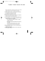
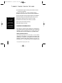
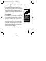
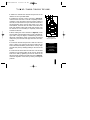
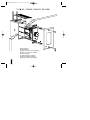
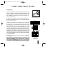
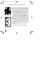
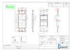
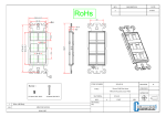
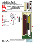
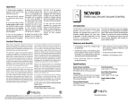
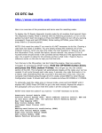
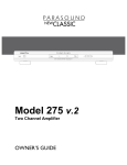
DS00101C/VCS-2D
2/5/99 1:32 PM
Page 12
M O D E L
VCS-2D
VCS-2D
PREMIUM STEREO VOLUME CONTROL
INSTALLATION & OPERATION GUIDE
DS00101C/VCS-2D
P
2/5/99 1:32 PM
S
R E M I U M
Page 1
T E R E O
V
O L U M E
C
O N T R O L
VCS-2D
Premium Stereo
Volume Control
TABLE OF CONTENTS
Introduction
1
Features and
Benefits
1
Installation
Considerations 3
Installation
Operation
8
Introduction
The VCS-2D is a wall-mount, Decora® style speaker volume
control. It connects between the speaker-level output of an
amplifier, speaker selector, etc. and a pair of speakers.
A perfect application for the VCS-2D is adjusting the volume
of remotely located speakers.The VCS-2D adjusts the volume
of speakers connected to it by attenuating the amplifier signal.
Niles volume controls use autoformers instead of L-pads for the
volume controlling element. This assures minimal internal
power dissipation with virtually no power wasted as heat.
10
Specifications 10
Features and Benefits
The VCS-2D offers a number of improvements over other
volume controls.
1
●
Interchangeable Decora-style inserts for fast, easy color
change. Inserts and knobs (sold separately) are available
in a variety of colors.
●
The VCS-2D uses a 12 position control, which is superior
to 10 position designs. You get a broader range of adjustment — there are 10 steps of attenuation instead of 8.
DS00101C/VCS-2D
P
2/5/99 1:32 PM
R E M I U M
S
Page 4
T E R E O
V
O L U M E
C
O N T R O L
Steps 11-6 attenuate -3 dB per step; steps 5-2 are -6 dB
per step. Step 12 is “full-on” and step 1 is “full-off”.
●
Greater dynamic range — you get 42 dB of total attenuation instead of the typical 20 or 30 dB.
●
POP-FREE switching between all steps.
●
100% tested, electronically and acoustically, for frequency
response, distortion and power handling.
●
The connectors on the VCS-2D are removable and
accommodate up to 14 gauge speaker wire. The
connectors simplify your installation:
• The speaker wires are easier to attach—no heavy
control to hold onto.
• The control may be removed without disconnecting
any wiring.
• ”Wire-Guard” barriers between each connector
terminal reduce the chance of a short-circuit.
●
Mounting depth of only 2 9/16”. Fits into standard 18 cu. in.
1-gang electrical boxes.
●
Printed circuit board construction uses no hand wiring,
assuring high reliability.
2
DS00101C/VCS-2D
P
2/5/99 1:32 PM
S
R E M I U M
TOOLS REQUIRED
• No. 2 Phillips
Screwdriver
• 1/8" Standard
Slotted Screwdriver
• 1/4" Standard
Slotted Screwdriver
• Wire Stripper
• 5/64" Allen Wrench*
Page 5
T E R E O
V
O L U M E
C
O N T R O L
●
Isolated left and right channel grounds make it safe for
use with any amplifier.
●
●
May be used with 4, 6, or 8 ohm speaker systems.
Ideal for both home and commercial sound installations.
●
Only screwdriver and wire stripper required for installation.
●
Power handling: 60 watts/channel peak music power.
●
Frequency response: 20 Hz to 20 kHz ±1.2 dB.
●
Available colors: White, Bone, Almond, or Black.
●
Ten year parts and labor warranty.
●
Proudly made in the USA.
Installation Considerations
The VCS-2D is a Decora-style module and is designed to
use standard Decora-style faceplates and mounting
hardware. Decora faceplates (up to 6-gang) with colormatched plate screws are available from your Niles dealer.
P-Rings and Electrical Boxes
The mounting depth of the VCS-2D is 2 9/16 ”. When
installed, the unit extends 2 1/16” behind the sheetrock wall
(assuming 1/2” sheetrock). For installation, you must choose
between a standard light switch plaster ring (p-ring) or a
standard 18 cu. in. (or larger) electrical box. Suitable p-rings
3
* Only required if changing color of unit.
DS00101C/VCS-2D
P
2/5/99 1:32 PM
R E M I U M
S
Page 8
T E R E O
V
O L U M E
C
and electrical boxes are available from your Niles dealer or
local electrical supply company. Using the p-ring is best
because it gives you unobstructed access to the full depth
of the wall. In some instances, the use of a p-ring may be
inappropriate, such as in a retro-fit (existing) installation, or
when building codes require that wall devices be enclosed
in electrical boxes. Contact your local building code and
inspection department if unsure.
O N T R O L
"Tech Tip"
Type of Speaker Wire
For most applications, we recommend you use 16 or 18
gauge, stranded copper speaker wire for the VCS-2D connections. For wiring runs longer than 80 feet, 14 gauge wire
is recommended. Using speaker wire larger than 14 gauge
for the VCS-2D connections is not recommended — the
wire may not fit into the connectors. Never use solid-core,
aluminum, or “Romex” type wire with the VCS-2D. When
running speaker wires inside walls, most states and municipalities in the U.S. specify that you must use a special type
of speaker wire. Usually, the requirement is that the wire
has a specific “CL” fire rating, such as “CL-2” or “CL-3”.
Consult your Niles dealer, building contractor, or local
building and inspection department if unsure about which
type of wire is best for your application.
Wire size is
expressed by it's
AWG (American
Wire Gauge)
number. The lower
the AWG number,
the larger the wire,
i.e., 12 AWG wire is
physically larger than
14 AWG.
VCS-2D Mounting Location
Convenient mounting locations for the VCS-2D are:
4
DS00101C/VCS-2D
P
2/5/99 1:32 PM
S
R E M I U M
Page 9
T E R E O
V
O L U M E
C
O N T R O L
●
Near entryways or exits
●
Near a desk
●
At your bedside
●
Close to a telephone
●
Near other wall controls (see caution next below)
DO NOT INSTALL THE VCS-2D INTO ELECTRICAL BOXES
WITH 110 VOLT DEVICES
Some states or municipalities allow devices such as the
VCS-2D to be installed into the same electrical box as 110
volt devices, provided a “low-voltage partition” is used
between the devices. We do not recommend this. Speaker
wires can act as an “antenna” for electrical noise. Locating
speaker wires too close to a light switch or dimmer may
cause a “popping” or “buzzing” sound to be heard through
the speakers. If you must locate the VCS-2D near electrical
devices, install it in a separate metal electrical box, ground
the box to the electrical system ground, and route the
speaker wires several feet away from the electrical wiring.
Figure 1
Removing the Knob
5
Changing the Color of the VCS-2D
The Decora-style insert and knob on the VCS-2D are
removable, allowing fast and easy color changes as needed.
Inserts and knobs are available in a variety of colors. If you
need to change the color of the VCS-2D:
DS00101C/VCS-2D
P
2/5/99 1:32 PM
R E M I U M
S
Page 10
T E R E O
V
O L U M E
C
O N T R O L
1. Obtain the VCS-2D knob and Decora-style insert in the
desired color from your Niles dealer.
2. Holding the VCS-2D control as shown in (Figure 1),
make sure that the knob is turned completely counterclockwise, to the off position. Note the current position of
the knob; this will ensure that you install the new knob in
the same position as the old one. Next, using a 5/64” allen
wrench/driver, locate the two set screws on the side of the
knob and carefully loosen both screws until the knob may
be removed. It is not necessary to completely remove the
screws from the knob.
3. Next, holding the control as shown in (Figure 2), locate
the two plastic mounting tabs at the top rear of the Decorastyle insert. Using two fingers, simultaneously press both
tabs down (towards the center of the insert) and forward
(away from you) until the insert pops free from its mounting slots.
4. Locate the new Decora-style insert. Hold the control so
that it is facing you. Insert the two bottom tabs into the
bottom slots first, followed by the two tabs on the top. Snap
the insert into place by carefully pressing on the front of the
insert.
5. Locate the new knob. Place the new knob onto the shaft
and align it to the same position as the old one. Secure the
knob to the shaft by tightening the two set screws on the
side of the knob. Holding the VCS-2D as shown in (Figure 1),
check the alignment of the knob by turning it through all
positions.
Figure 2
Removing the
Decora-style Insert
"TECH TIP"
Do not exert
excessive pressure on
the plastic
mounting tabs.
6
DS00101C/VCS-2D
P
2/5/99 1:32 PM
R E M I U M
S
Page 7
T E R E O
V
O L U M E
C
O N T R O L
a
b
e
c
d
f
g
(a) Electrical Box
(b) Speaker Wire
(c) VCS-2D Volume Control (supplied)
(d) Snap-on Color Insert (supplied)
(e) Knob (supplied)
(f) Device Screws (2 supplied)
(g) Decora Wallplate (supplied)
(h) Faceplate Screws (2 supplied)
7
h
DS00101C/VCS-2D
P
2/5/99 1:32 PM
R E M I U M
S
Page 6
T E R E O
V
O L U M E
C
O N T R O L
Installation
If you are installing the VCS-2D into an existing wall, take
time to consider any possible obstructions which may be
hidden inside the wall, such as wood and metal studs; electrical, telephone or other types of wiring; plumbing; conduit; old wall safes; etc.
1. Install the electrical box or p-ring in the usual manner.
2. Run all the necessary wiring to the VCS-2D. Label the
wires for future reference.
3. Make the connections to the VCS-2D. Locate the connectors for the VCS-2D (remove them if they are plugged
in). Next, strip 1/4” of insulation from the end of each wire.
Tightly twist the end of each wire until there are no frayed
ends. Insert each wire into the appropriate hole on the
removable connector blocks; secure the wiring to the connectors by tightening the small connector screws. Be certain that proper phasing is observed—connect the positive
terminals on the VCS-2D to the positive terminals on the
amplifier and speakers; the negative terminals on the VCS2D to the negative terminals on the amplifier and speakers.
See (Figures 3 and 4).
Figure 3
Wiring the Connectors
Receiver
To
Amplifier (Input)
VCS-2D
To
Speakers (Output)
4. Plug the connectors into the VCS-2D as shown in (Figure 5)
on next page.
The inputs of the VCS-2D are the connector pins
labeled “AMPLIFIER”
. The outputs are the connector
pins labeled “SPEAKERS”
. Be sure not to reverse these
connections or the VCS-2D will not function properly.
Speakers
Figure 4
Wiring Diagram
8
DS00101C/VCS-2D
P
2/5/99 1:32 PM
R E M I U M
Figure 5
Installing the
Connectors
S
Page 3
T E R E O
V
O L U M E
C
O N T R O L
5. Secure the VCS-2D to the electrical box or p-ring. Insert
the 11/4” long device screws into the oblong-shaped screw
holes on the top and bottom of the VCS-2D. Note that the
oblong shape of the screw holes allow you to position the
VCS-2D so that it is vertical. Position the VCS-2D so that the
screws are aligned with the threaded holes in the electrical
box or p-ring. Tighten the screws using a phillips screwdriver. DO NOT OVER-TIGHTEN. In some instances, you may
need to loosen these screws several turns to allow the VCS-2D
to fit flush with the Decora cover plate. See (Figure 6).
6. Use the shorter plate screws to fasten the Decora faceplate
to the VCS-2D. DO NOT OVER-TIGHTEN THE PLATE
SCREWS OR YOU MAY DAMAGE THE FACEPLATE. Line up
all the screws in the same direction for a finished look.
NOTE: Certain “old work” or “retro-fit” boxes, such as the
Carlon B225R, have a plastic “lip” which interferes with the
Decora faceplate screws. This lip prevents you from being
able to tighten these screws completely. To make the clearance necessary for these screws, you must remove the parts
of the lip causing the interference. There are two ways to
accomplish this:
1. Drill through the lip of the box at the screw points.
2. Cut notches into the lip with a pair of diagonal cutters.
Figure 6
Loosening the Screws
for a Flush Fit
9
DS00101C/VCS-2D
P
2/5/99 1:32 PM
R E M I U M
S
Page 2
T E R E O
V
O L U M E
C
Operation
1. Make sure the amplifier or receiver power is OFF and set
the volume to minimum.
2. Set the VCS-2D volume to maximum (fully clockwise).
3. If you are using a Niles speaker selection system, locate
the ON/OFF button which corresponds to the speaker pair
you wish to play. Set it to the ON position.
4. Turn on the amplifier or receiver and select a source,
such as the tuner or CD player.
5. Slowly turn up the amplifier or receiver volume and set it
to a comfortable (not maximum) listening level. Be careful
not to overdrive or "clip" your amplifier. If the sound
becomes muddy or distorted, you have reached the limit of
your amplifier’s volume capability and should quickly
reduce the volume to avoid damaging your speakers.
6. Adjust the volume of the speakers to the desired listening
level using the VCS-2D. If all the speaker pairs in your system are equipped with Niles volume controls, you can leave
the amplifier or receiver volume set at one position and use
the Niles controls exclusively.
7. You can turn off the speakers by turning the knob on the
VCS-2D fully counter-clockwise, or by pressing the ON/OFF
button on your speaker selector.
O N T R O L
SPECIFICATIONS
Audio Power
Handling
60 Watts/channel
peak music power
Mounting
In-wall, fits into most
18 cu. inch singlegang electrical boxes
at least 2 3/4” deep,
Decora-style faceplate
Wiring Requirements
Individual runs of
2-conductor speaker
wire, 14-22 gauge
Unit Dimensions
1 5/8" wide x 2 5/8"
high
Face Plate Dimensions
Decora wall plate;
2 3/4” wide x 4 1/2”
high
Depth Behind Plate
2 9/16”
10
DS00101C/VCS-2D
2/5/99 1:32 PM
Page 11
NILES ®
Niles Audio
Corporation
www.nilesaudio.com
12331 S.W. 130 Street
Miami, Florida 33186
Tel: (305) 238-4373
Fax: (305) 238-0185
©1999 Niles Audio Corporation. Niles and the Niles logo are registered
trademarks of Niles Audio Corporation. Decora is a registered trademark of Leviton
Manufacturing Company. DS00101C