1
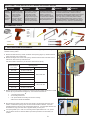
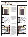
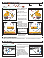
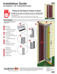
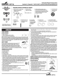
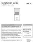
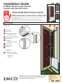
Installation Guide
for EMCO® Woodcore Triple-Track and
Colonial Triple-Track Storm Doors
Please Do Not Return Product to Store!
PLEASE call the storm door Solution Center at 1-800-933-3626
with any questions regarding installation, mis-cut part replacement, lost part replacement, or anything else related to
your storm door purchase.
• If your abilities do not match the requirements of this installation, contact an experienced contractor.
• EMCO has no responsibility in regard to the post-manufactured assembly and installation of EMCO® products.
PARTS OVERVIEW
Your storm door should contain the
following parts:
1
5
1
1
Rain Cap
2
Door Frame
3
Hinge Rail with 4 hinges
2
6
6
(Hinge Side Z-bar)
4
Ventilating Glass panel (2)
5
Insect Screen
6
Latch Rail
3
(Handle Side Z-bar)
7
Sweep, vinyl
8
Sweep, metal
9
Sweep Fin
4
Not Shown
10
Hardware Kit, includes
Door Mounting screws
Handle Set
Closer Kit
3
8
Figure 1
EMCO Enterprises, Inc., is a wholly owned subsidiary of Andersen Corporation. EMCO manufactures and supports the limited warranties for Andersen® and EMCO® doors. “Andersen”,
“EMCO” and all other marks where denoted are trademarks of Andersen Corporation.
©2011 Andersen Corporation. All rights reserved.
9
7
EMCO Enterprises, Inc.
PO Box 853
Des Moines, IA 50306-0853
Rev 6-2011 11025
P/N 503571
SAFETY FIRST - Please read and follow all warnings and cautions in this guide.
warning
Entry door
hardware
and handle
may
become
hot when
exposed to
sunlight.
Improper use of hand
or power tools could
result in injury and/or
product damage.
Follow equipment
manufacturer’s
instructions for safe
operation. Always
wear safety glasses.
warning
Windows and doors
can be heavy. Use safe
lifting techniques and
a reasonable number
of people with enough
strength to lift, carry, and
install window and door
products to avoid injury
and/or property damage.
warning
The insect screen is
intended for reasonable
insect control and not the
retention of objects or
persons within the interior.
The insect screen material
will not stop a person from
falling through the door.
warning
warning
Metal fasteners and other hardware components may
corrode when exposed to preservative treated and
fire-retardant treated lumber. Obtain and use the
appropriate size stainless steel fasteners and hardware
as called out by the installation guide to fasten unit
to any rough opening made from pressure treated
and fire-retardant treated lumber. Failure to use the
appropriate materials for the installation may cause a
failure resulting in injury, property or product damage.
RECOMMENDED TOOLS
• Safety Glasses
• Drill
• Tape Measure
• Drill Bits
• 3/32”
• 1/8”
• 5/32”
• 5/16”
• 7/16”
• 5/8”
• Center Punch
• Hacksaw
• Hammer
• Square
• Scissors
• Screwdrivers
• Pliers
• Level
• Pencil
1. VERIFY MOUNTING REQUIREMENTS
To install the storm door, you must verify that there is the necessary opening width and height and a
sufficient mounting surface.
H
1. Measure the width at the top, middle, and bottom of the opening (Figure 2). Measure from the
inside of the brick mold or exterior trim.
. Measure the height at the center of the opening. Measure from the inside of the brick mold or
exterior trim, down to the top of the bottom sill.
W1
3/4”
Use the this table to determine if your storm door will fit into the opening:
Nominal Storm
Opening Sizes
*
Door Sizes
W 1 - 3 (width)
36” x 80”
35 3/4” TO 36 3/8”
34” x 80”
33 3/4” TO 34 3/8”
33” x 80”
32 3/4” TO 33 3/8”
32” x 80”
31 3/4” TO 32 3/8”
30” x 80”
29 3/4” TO 30 3/8”
36” x 78”
35 3/4” TO 36 3/8”
32” x 78”
31 3/4” TO 32 3/8”
30” x 78”
29 3/4” TO 30 3/8”
1”
H (height)
2 1/2”
W2
80” TO 80 7/8”
78” TO 78 7/8”
Figure 3
W3
3. Make sure that the brick mold or exterior trim meets the mounting surface requirements to install
the rain cap, hinge rail and latch rail (Figure 3). You must have a minimum of:
•
•
•
*
1” mounting surface depth.
3/4” mounting surface front.
2 1/2” space between the existing door and the mounting
surface for the handle set installation.
Figure 2
to top of door
2 1/2”
37 3/4”
4. Most homeowners prefer to have the storm door handle on the same side as the entry door
*
handle. In shallow door openings, this can cause the two handles to interfere. Check for
potential interference using the rough measurements (Figure 4). If you anticipate that there will
be interference, hinge your storm door on opposite side of your entry door.
For opening widths up to 1” wider or for mounting surface depth between 5/8” - 3/4”, please
call our Solution Center at 1-800-933-3626 to purchase a special kit to accommodate your
situation.
Figure 4
2. INSTALLATION PREPARATION
In this step, you will remove the ventilating glass panels.
. Lay the door flat on a protected surface with the exterior side down.
TIP: Lay on door carton.
Figure 5
2. Remove the lower ventilating glass panel by pulling the latches
at the bottom toward each other. Lift the lower portion of the
ventilating glass panel up and then rotate it to remove (Figure 5).
3. Repeat the previous step to remove the upper ventilating glass
panel.
4. Stand each glass panel on its edge and out of the way to prevent
damaging them.
In this step, you will remove the insect screen.
5. Remove the insect screen by pulling the two pins toward each
other, then pull the insect screen up. Rotate the insect screen out of
its track (Figure 6).
6. Stand the insect screen on its edge and out of the way to prevent
damaging to it.
Figure 6
RIGHT HINGE
LEFT HINGE
In this step, you will determine which side of the opening to use as the
hinge side.
7. Left-hinged door (Figure 7) - Looking at the door from the exterior, a
left hinged storm door will have the hinge rail on the left side of the
storm door. Refer to the illustrations in the column on the left side of
the installation guide under this heading:
LEFT HINGE
8. Right-hinged door (Figure 8) - looking at the door from the exterior,
a right hinged storm door will have the hinge rail on the right side of
the storm door. Refer to the illustrations in the column on the right
side of the installation guide under this heading:
RIGHT HINGE
Figure 7
Remember, any mis-cuts during your storm door installation can be
replaced free of charge. Just call our Solution Center at
1-800-933-3626.
exterior
views
Figure 8
3. PREPARE STORM DOOR FOR HANGING
1 - #8x1”
Tools needed:
8 - #8x1”
1/8”
LEFT HINGE - Exterior View (Figure 9)
1
In this step, you will hang the rain cap
against the top mounting surface (Figure
9).
1. Center the rain cap in the door
opening.
2. Using a pencil, mark the hinge side
hole on the mounting surface. Set
rain cap aside.
3. Using the drill and 1/8” drill bit, drill a
hole in the mounting surface.
. Place the rain cap back on the door
opening.
5. Screw a #8 x 1” color-matched screw
in the hole as indicated by the red
arrow, fastening the rain cap to the
mounting surface.
6. Do not install the remaining screws at
this time.
RIGHT HINGE - Exterior View (Figure 9)
1
In this step, you will attach the hinge rail
to the door frame.
Figure 9
Top
HINGE
SIDE
MIDDLE
SCREWS
3
2
Figure 10
Figure 11
Top
Interior
x4
1/4”
2
3
Figure 12
Bottom
interior
7. Place latch side edge of door frame
on the ground.
TIP: Lay on door carton.
8. Remove the two (2) middle screws
from hinge side edge of door frame
(Figure 10).
9. Using a 1/8” drill bit, drill 1” minimum
deep holes into the door frame
where you removed the screws in the
previous step.
10. Locate the top of the hinge rail (Figure
11).
11. Position the hinge rail along the
hinge-side edge of the door frame,
extending the top of the hinge rail
1/4” beyond the top of the door frame
(Figure 12).
12. The top hole of the second hinge and
the bottom hole of the third hinge
should line up with the holes drilled in
Step 9.
13. Use #8 x 1” unpainted screws to
fasten the second and third hinge. Do
not overtighten screws.
1. Using a 1/8” drill bit, drill 1” minimum
deep holes into the door frame
through the remaining holes in the
hinges.
15. Attach hinges to the door frame using
unpainted #8 x 1” screws. Do not
overtighten screws.
In this step, you will cut the bottom of the
hinge rail to its proper length.
Figure 9
HINGE
SIDE
MIDDLE
SCREWS
Top
3
2
Figure 10
Figure 11
Top
Interior
x4
3
1/4”
2
Figure 12
Bottom
interior
16. Measure the height of the door
3
2
Figure 13
opening on the hinge side, measuring
from the underside of the rain cap
to the door sill. You will use this
measurement to cut the hinge rail to
its proper length.
17. Measure the hinge rail, starting at the
top and then marking the bottom with
the measurement that you took of the
door opening (Figure 13).
18. Using the hacksaw, cut the hinge rail
to its proper length.
3
2
Figure 13
4. HANG HINGED STORM DOOR:
6 - #8x1”
Tools needed:
8 - #8x1”
1/8”
LEFT HINGE - Exterior Views
In this step, you will hang the storm
door in the opening.
RIGHT HINGE - Exterior Views
. Position the door in the opening so
1
3
2
Figure 14
Figure 15
that the edge of the hinge rail is flush
with the end of the rain cap, and the
top end of the hinge rail is butted up
against the underside of the rain cap
(Figure 14).
2. While holding door in position,
mark onto the mounting surface the
location of the top-most pre-drilled
hole in the hinge rail. Once marked,
remove door from opening and set
aside.
3. Using the 1/8” drill bit, drill a hole
in the mounting surface where you
placed the mark.
4. Reposition the door in the opening
and align the pre-drilled hole in the
hinge rail with the hole that you
drilled in the mounting surface.
5. Fasten the door to the mounting
surface using one (1) #8 x 1” painted
screw.
6. Using the level, make sure that the
door is plumb (straight up and down).
7. While holding door in position,
use the 1/8” drill bit to drill holes in
the mounting surface through the
pre-drilled holes in the hinge rail.
8. Fasten the hinge rail to the mounting
surface using five (5) #8 x 1 painted
screws (Figure 15).
9. Open the storm door.
0. Using the 1/8” drill bit, drill holes in
the door jamb through the pre-drilled
holes in the hinge rail.
. Fasten the hinge rail to the door
jamb using eight (8) #8 x 1 unpainted
screws (Figure 16). Do not
overtighten the screws
1
3
2
Figure 14
Figure 15
In this step, you will install the insect
screen and ventilating glass panels.
2. Now that the door is hanging, install
Figure 16
the insect screen and two ventilating
glass panels in the reverse order of
what was done in step 2. (Figures
5 & 6)
Figure 16
5. INSTALL REMAINING FRAME COMPONENTS:
8 - #8x1”
Tools needed:
1/8”
LEFT HINGE - Exterior Views
In this step, you will finish fastening
the rain cap to the top mounting
surface.
RIGHT HINGE - Exterior Views
1. Close the storm door.
2. Adjust the rain cap so that the
1
1
gap between the rain cap and
door frame is the same along the
entire length of the rain cap.
3. Using the 1/8” drill bit, drill holes
in the mounting surface through
the pre-drilled holes in the rain
cap (Figure 17).
4. Fasten the rain cap to the
mounting surface using two (2)
#8 x 1” painted screws.
2
2
Figure 17
Figure 17
In this step, you will cut the bottom
of the latch rail to its proper length.
top
5. Measure the height of the door
6
6
Bottom
Figure 18
Figure 19
opening, measuring from the
underside of the rain cap to
the door sill. You will use this
measurement to cut the latch rail
to its proper length.
. Locate the top of the latch rail
(Figure 18).
7. Measure the latch rail, starting
at the top and then marking the
bottom with the measurement
that you took of the door
opening.
8. Using the hacksaw, cut the latch
rail to its proper length (Figure
19).
top
6
6
Bottom
Figure 18
Figure 19
In this step, you will attach the latch
rail to the mounting surface.
9. Position the latch rail so that the
1
1/4”
2
6
Figure 20
top end of the latch rail is butted
up against the underside of the
rain cap (Figure 20).
10. Close the storm door.
11. Measure the space between the
latch rail and the storm door. This
space should be 1/4” along the
entire length.
12. Using the 1/8” drill bit, drill holes
in the mounting surface through
the pre-drilled holes in the latch
rail. Use the pre-drilled holes in
the latch rail as guides.
13. Fasten the latch rail to the door
opening using six (6) #8 X 1”
painted screws.
1
1/4”
6
2
Figure 20
6. INSTALL WEATHER SEALING COMPONENTS
Tools needed:
OR
2 - #8x1/2”
4 - #8x1/2”
1/8”
LEFT HINGE - Interior Views
For doors with a Brass or Nickel finish
sweep only: in this step, you will install
the bottom sweep fin (Figure 21).
9
RIGHT HINGE - Interior Views
9
1. Slide the sweep fin into the fin track
flush with the sweep end.
2. Use pliers to crimp the ends of the
track legs (both ends) to secure the
fin.
3. Trim off excess sweep fin material.
8
8
In this step, you will install the sweep.
9
9
4. Open the door and slide the sweep
5.
Figure 21
6.
.
2
8.
8
onto the bottom of the door frame.
Make sure that the screw slots on
the sweep are towards the interior.
Position the door sweep so that it is
flush with the latch-side of the door
frame (Figure 22).
Close the door.
From the interior, adjust the sweep
up or down until the sweep fins
come into contact with the door sill.
Using the drill and 1/8” drill bit, drill
a starter hole into the door using the
pre-drilled hole slots as guides.
Figure 21
2
8
CAUTION
Do not drill completely through
door. This will create an
unnecessary hole in the door
and may cause water and air
infiltration.
Interior floor
8
9. Fasten the sweep to the door using
two (2) or four (4) #8 X 1/2 colormatched (to sweep) screws.
Figure 22
8
Interior floor
Figure 22
7. INSTALL CLOSER AND HANDLE SET
1. Refer to the instructions in the hardware kit box to install the closer and the handle set. Many home improvement stores or locksmiths can make
duplicate keys.
8. ADJUST THE CLOSER
Tools needed:
In this step, you will adjust the door closer.
LEFT HINGE - Interior Views
SLOWER
FASTER
Figure 23
1. Locate the adjustment screw at the end of the
closer that attaches to the door frame (Figure
23).
2. Open the door and then let it close to note the
speed at which the door closes.
3. Using a Phillips head screwdriver to adjust
the closer to the desired speed:
• For a faster closing speed, turn
the adjustment screw to the left
(counterclockwise).
• For a slower closing speed, turn the
adjustment screw to the right (clockwise).
4. Test the speed at which the door closes after
each adjustment. Adjust the screw more, if
needed, to achieve the desired door closing
speed.
RIGHT HINGE - Interior Views
SLOWER
FASTER
Figure 23
REGULAR MAINTENANCE
WINDOW GLASS – The glass may be cleaned with any household glass cleaner. Keep glass cleaners away from painted parts and brass/nickel
components.
PLASTIC PARTS – Plastic door components may be cleaned using a mild soap and water mixture and by gently rubbing the affected area. Do not use harsh
abrasives or any product that contains chlorine.
ALUMINUM PARTS – Aluminum parts on the door may be cleaned using a mild soap and water mixture and by gently rubbing the affected area. Mineral
spirits may be used and will not harm the paint. This will remove many items such as glue residue. Do not use harsh abrasives or any product that contains
chlorine.
LIMITED WARRANTIES
PRODUCT LIMITED WARRANTY
DOOR FRAME: EMCO Enterprises, Inc. (EMCO) warrants the door frame, hinges, and painted finish on EMCO® storm door products to be free from defects in manufacturing, materials,
paint adhesion, or workmanship, under normal use, for ten (10) years or as long as the original consumer purchaser owns the home in which the door was initially installed, whichever is
shorter.
COMPONENTS: EMCO warrants the non-glass and non-insect screen fabric components of EMCO® storm doors (including brass and nickel hardware finish and the mechanical functions of locksets, closers, windows and insect screens) to be free from defects in manufacturing, materials and workmanship for a period of one (1) year from the date of original retail purchase or for as long as the original consumer purchaser owns the home in which the door was initially installed, whichever is shorter. Kick panel retention within the frame is not covered
under this warranty.
In the event a door frame, hinges, insulated glass or a component fails as a result of a defect in manufacturing, materials or workmanship within the limited warranty period specified
above, and upon written proof of purchase, EMCO, at its option, will: provide a replacement door frame, hinge, and/or components without charge – installation is not included. Such
replacement or repair is warranted for the remainder of the original limited warranty period. Please locate the door serial number and written proof of purchase and contact EMCO
Consumer Support at 1-800-933-3626.
“OOPS-PROOF” INSTALLATION LIMITED WARRANTY
EMCO Enterprises, Inc. (EMCO) warrants that any part lost or mis-cut during the original installation of your EMCO storm door will be repaired or replaced at no additional charge within
ninety (90) days of the date of original purchase. This limited warranty will not apply if the part has been misused, abused or altered. Cutting parts not specified by the installation guide
or mis-drilled parts are not included in this warranty.
In the event a part is lost or mis-cut within the limited warranty period, EMCO, at its option, will provide the appropriate replacement part – installation is not included. Please locate the
door serial number and written proof of purchase and contact EMCO Consumer Support at 1-800-933-3626.
GENERAL LIMITED WARRANTY INFORMATION
The limited warranties set forth in this document are the only express warranties (whether written or oral) applicable to EMCO® storm doors, and no one is authorized to modify or expand
these limited warranties. All warranty claims must be made during the applicable warranty periods.
ALL IMPLIED WARRANTIES INCLUDING MERCHANTABILITY AND FITNESS FOR A PARTICULAR PURPOSE ARE LIMITED TO THE APPLICABLE STATUTE OF LIMITATION,
BUT IN NO CASE WILL THEY EXTEND BEYOND THE TERM OF THE LIMITED WARRANTIES SET FORTH ABOVE. EMCO EXCLUDES AND WILL NOT PAY FOR INCIDENTAL
OR CONSEQUENTIAL DAMAGES, WHETHER ARISING OUT OF CONTRACT, TORT OR OTHERWISE, AND ITS LIABILITY WILL IN ALL INSTANCES BE LIMITED TO THE
REPAIR OR REPLACEMENT OF THE DEFECTIVE PRODUCT.
Some states do not allow the exclusion of incidental and consequential damages, or limitation of the duration of an implied warranty, so the above limitations or exclusions may not apply
to you.
This limited warranty gives you specific legal rights, and you may also have other rights that may vary from state to state and in Canada.
What is NOT covered by this limited warranty: Damage caused by 1) improper installation, maintenance, or use; 2) chemicals or airborne pollutants, such as salt or acid
rain; 3) acts of God, including wind damage; 4) Products not manufactured by EMCO
EMCO Enterprises, Inc. is a wholly owned subsidiary of Andersen Corporation. EMCO manufactures Andersen® and EMCO® storm doors. EMCO supports the limited warranties covering Andersen® Storm and Screen Doors. “Andersen”, “EMCO” and all other marks where denoted are trademarks of Andersen Corporation. ©2011 Andersen Corporation. All rights
reserved.
Reprinted and effective as of May, 2011.