1
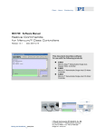
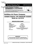
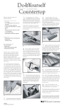
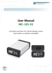
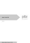
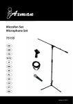
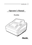
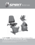
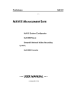
Motor controller 4ch
User manual
November 19, 2002
Release: 1.30
C-400
2002 by Pacific Laser Equipment
Pacific Laser Equipment
C-400 User Manual
Name: C-400UM
Release: 1.30
Release Date: November 19, 2002
© 2001 by
Pacific Laser Equipment
PLEquipment, 3941 S. Bristol St. Unit D-122, Santa Ana, CA. 92704,
( 509-355-5155, Fax: 509-355-5155, Email: [email protected]
Page 1 of 21
Motor controller 4ch
User manual
November 19, 2002
Release: 1.30
C-400
2002 by Pacific Laser Equipment
Table of contents:
1. Introduction
1.1 Product description
1.2 Labels
3
1.3 Operation
2. Block diagram
6
3. Technical specs
7
4. Test and troubleshooting
8
5. Command structure
5.1 Single commands
5.2 Compound commands
5.3 Macro commands
5.4 Reporting commands
9
6. Cable connections
10
7. Software
11
8. Commands
12
9. LabView
9.1
VIs (Drivers)
9.2
Example programs
13
10. OEM versions
18
PLEquipment, 3941 S. Bristol St. Unit D-122, Santa Ana, CA. 92704,
( 509-355-5155, Fax: 509-355-5155, Email: [email protected]
Page 2 of 21
Motor controller 4ch
User manual
November 19, 2002
Release: 1.30
C-400
2002 by Pacific Laser Equipment
1. Introduction
1.1.
Product description.
The C-400© is a unique 19inch rack mountable 4ch DC servo motor controller with integrated DC motor
amplifiers on board. It consists of precision amplifiers, power supplies, insulation transformers,
rectifiers, and voltage regulators and TTL logic built around the Mitsubishi M 50734SP processor.
All this is compactly packaged in a 6-part 19 x 3.5 x 10" rack-mount anodized aluminum case.
The DC voltage output can deliver up to +/-12V making the controller compatible with most mechanics
from: Newport, PI, OptoSigma and ThorLabs.
PC control is done via a null modem serial-interface cable that can be purchased as a STANDARD.
On the rear panel the user has access to the AC power plug and the ON / OFF switch.
The fuses are located inside the 19” chassis.
The controller is delivered with this User Manual, power cord and one null-modem serial cable.
This manual is provided as an aid in operating and programming the C-400© DC-Motor Controller.
This servo-controller is intended for motion control in research and industrial applications providing in a
single package a complete stand-alone control system for the smaller DC servo motors used in highprecision positioning systems.
The C-400© utilizes quadrature encoder signals for position feedback and depending on the resolution
of the encoder scale, incremental resolutions of 50nm to 0.1µm can be achieved.
The C-400© provides servo-control of position, velocity, and acceleration. Although each parameter is
programmable, each is also set to a programmable default value upon power-up.
Using the built-in commands and features, the user will very quickly be able to command the motor to
move to any desired position. During the motion the velocity and acceleration will be controlled in
accordance with the most recent settings of the controller parameters. It is not necessary to set them
up anew for each move. The starter package comes with all connecting cables and software necessary
for immediate operation.
Each axis has provision for two limit switches, in addition to a differential quadrature encoder input with
index capabilities. For highest precision in a homing application, motion is commanded until the
reference switch is encountered, then continues at a slower rate until the encoder index is found. With
this procedure, the home position may be repeated to an accuracy of one encoder count, or the
ultimate accuracy of the system.
All limit and reference switch inputs are sensed through line receivers with 1 volt of hysteresis for noise
rejection. The encoder inputs use differential line receivers with 300 mV of hysteresis. They may be
used with single encoders, as well. A capture/compare circuit is used to sense any change in the
state of the limit and reference switches. When any one of them changes, a maskable interrupt
is generated. These are several additional sources of interrupt, including excessive error,
encoder error index, and absolute and relative position breakpoints.
PLEquipment, 3941 S. Bristol St. Unit D-122, Santa Ana, CA. 92704,
( 509-355-5155, Fax: 509-355-5155, Email: [email protected]
Page 3 of 21
Motor controller 4ch
User manual
November 19, 2002
Release: 1.30
C-400
2002 by Pacific Laser Equipment
1.2. Labels.
Rear panel labels indicate the functions for every connector, the unit serial number and display the
power requirements.
1.3. Operation.
Controller operates only controlled by a host PC via the serial cable provided with the unit.
The operating voltage for the DC motors may change in the range from –12V to +12 V.
Serial communication is set by factory to 9600 baud, 8 data, 1 stop, no parity. Internal buffers are used,
so there is no handshake required. Use a null modem cable for connection.
Setting Motion Control Parameters
Prior to commanding the connected motor or stage to move, the servo-control as well as the velocity
and acceleration values have to be set. If you are using host software with valid configuration files or
the C-400© is set up to default to correct parameter settings, then you may skip this section.
Each stage could require its own set of parameters for proper operation.
They can be modified as appropriate for the actual setup. The settings are not particularly critical, so
you can vary parameters by +/- 50% to achieve better settling performance.
Operating Motors and Stages
Type MN<return>. C-400© is now on-line and ready for motion. If the motor oscillates or begins to "run
away" when the MN command is given, remove power and read further before continuing.
Enter MR1000 <return>. The motor should move 1000 encoder counts in the positive direction. When it
stops, enter TP <return>. The position should be very close to 1000. Now enter TT,TE <return> in order
to read the target and the position error. This reports where the motor should be (1000) and the
distance of the actual position from this target. If the reported position was 998, then the reported error
will be 2. If the reported position was 1002, the reported error will be -2.
To read all values at the same time, enter TT,TP,TE <return>. Now all three values are reported.
Now enter MR-1000 <return>. The motor should return to zero, or home, position.
Press <return> again. The motor should move another 1000 counts in the negative direction. Press it
again and again. The motor should move each time.
Now try GH <return>. The motor should return to the position it occupied when power was applied.
Now for advanced programming: enter MR1000,WS100,TE <return>.
The motor should move 1000 counts positive. When it arrives at this position, it should report how close
it came to the target.
For a longer move, enter MR100000<return> and verify that the motor has moved that distance. Press
the <return> key again and see that the motor moves the same amount in the same direction. Press it
again and again. A GH<return> command will return to the previously defined HOME position.
While in motion, we could have entered TV and pressed the <return> key
as often as desired to read the actual number of encoder counts moved during the last 0.4 seconds.
Set the acceleration to a lower value, such as SA10000 <return> and see the velocity increase and
decrease over a longer period. Set the velocity to various values and issue commands to move to
various positions using either MA or MR commands.
Move the stage some distance away from the end, say 100,000 counts, and try this:
MR50000,WS100,WA500,MR-50000,WS100,WA500,RP9 <return>.
The stage should cycle back and forth 50,000 counts with a delay of a half-second at each end.
It should do this ten times—once by command followed by nine repetitions.
PLEquipment, 3941 S. Bristol St. Unit D-122, Santa Ana, CA. 92704,
( 509-355-5155, Fax: 509-355-5155, Email: [email protected]
Page 4 of 21
Motor controller 4ch
User manual
November 19, 2002
Release: 1.30
C-400
2002 by Pacific Laser Equipment
Multi-Axis Control
The axis number will proceed whenever a specific axis needs to be moved or read.
Example: 1MR50000, 2MR-30000, 3TP, 4GH.
Default Values
C-400© has been designed to be as easy to use as possible. When shipped, the C-400© comes with
(factory) default settings. These settings can be read and changed using the Read_C400.vi and the
SET_C400.vi In most cases, the factory default values will be appropriate for the application.
Limit Sensors
During operation, the limit sensors (or switches) are used to stop the motion at the end of the allowable
travel range. Only one of the two switches will interrupt motion in a given direction.
When connecting other motor drives or mechanics, the correct limit switch wiring must be determined.
To do this, set the system into a safe position, set a low velocity with the SV command, begin motion
with an MR, MA or FE command and enable limit switch operation with the LN command. While the
motor is moving, actuate the limit switch toward which it is moving. If the motor stops, that is the correct
switch to connect at the end of desired motion for that direction. If the motor does not stop, actuate the
other limit switch. If the motor still does not stop, remove power and read further.
Each axis has provision for two limit switches and a reference switch, in addition to a
differential quadrature encoder input with index capabilities. For highest precision in a homing
application, motion is commanded until the reference switch is encountered, then continues at
a slower rate until the encoder index is found. With this procedure, the home position may be
repeated to an accuracy of one encoder count, or the ultimate accuracy of the system.
All limit and reference switch inputs are sensed through line receivers with 1 volt of hysteresis
for noise rejection. The encoder inputs use differential line receivers with 300 mV of hysteresis.
They may be used with single encoders, as well.
A capture/compare circuit is used to sense any change in the state of the limit and reference
switches. When any one of them changes, a maskable interrupt is generated. These are
several additional sources of interrupt, including excessive error, encoder error index, and
absolute and relative position breakpoints.
LM629 Data
1
Input register
6 (Read only)
Software reset
7 (Read only)
Interrupt register
2 (Read only)
Limit switch register
3 (Read only)
Configuration and output
6 (Read only)
LM629 Commands
0
(Desired channel selected by configuration register bits 6, 7, address 6)
©
The C-400 controller uses National Semiconductor LM629 integrated circuits to perform the
servo control functions. If the user wishes to program them directly, the programming is done
exactly as described in National's programming manual. For those users wishing to use the
C-400© in an interactive manual mode, joystick operation is possible also as an add-on option.
PLEquipment, 3941 S. Bristol St. Unit D-122, Santa Ana, CA. 92704,
( 509-355-5155, Fax: 509-355-5155, Email: [email protected]
Page 5 of 21
Motor controller 4ch
User manual
November 19, 2002
Release: 1.30
C-400
2002 by Pacific Laser Equipment
2. Block diagrams
2.1 General diagram.
2.2 Power supply block diagram
PLEquipment, 3941 S. Bristol St. Unit D-122, Santa Ana, CA. 92704,
( 509-355-5155, Fax: 509-355-5155, Email: [email protected]
Page 6 of 21
Motor controller 4ch
User manual
November 19, 2002
Release: 1.30
C-400
2002 by Pacific Laser Equipment
3. Technical specs
Number of motor channels
Maximum output voltage
Maximum current
Digital I/O channels
Control modes
Servo algorithm
Trajectory generation
1 to 4
- 12V to +12V
2 A peak
8 inputs, 5 outputs
Position and velocity
Proprietary
Trapezoidal
Incremental, single-ended or differential with index
Position encoder compatibility
1 MHz maximum
Communication
RS-232
Output type
Analog 0 to +/-12V
Control language
Two letter mnemonics, LabView 6.1 drivers,
Acceleration/deceleration, velocity,
position, digital filter gains, derivative
sampling interval, absolute and relative
Programmable functions
breakpoint positions, integration limit,
interrupt mask, maximum allowable able error
stop mode
Dynamic range
30 bits, (+/- 1,073,741,824)
Interrupts
Position breakpoints, limit switches, error limit
Addressing
Switch selectable. I/O mapped
Physical interface,
25-pin and 9-pin Sub D connectors
motors & I/O
Analog input:
0 to 5V (Optional through the I/O port).
Display:
Power out:
Power requirements:
Dimensions:
Enclosure
LED for internal power supply.
2.5W.
120V AC, 100mA.
5 x 2 x 3”
19” Rack. Aluminum (Black anodized or Aluminum)
PLEquipment, 3941 S. Bristol St. Unit D-122, Santa Ana, CA. 92704,
( 509-355-5155, Fax: 509-355-5155, Email: [email protected]
Page 7 of 21
Motor controller 4ch
User manual
November 19, 2002
Release: 1.30
C-400
2002 by Pacific Laser Equipment
4. Test and troubleshooting
Attention:
The unit uses AC 120V. This is a dangerous voltage.
Front and Back Panel Elements
Connectors :
RS-232
(1)
STAGES
(4)
AC 120V
(1)
Sub-D 9(m) Serial network input
Sub-D15(f) Motor connector
Standard AC 3 pin receptacle.
Indicators:
Power
Orange LED on front panel.
(1)
Fuses
The fuses are located inside the box. When replacing please use slow-blow 100mA.
AC Power
Make sure that the AC power used is always 120V.
Test
To test communication with the C-400© connect all cables and power-up than send the TP
command from any program capable to send ASCII commands via the COM port.
If the system is ready for operation the controller will respond with the encoder read-out.
Trouble Shooting
Problem (#1): The controller communicates and reports position values (TP), but the connected stage
or motor does not move.
Cause (#1): The 12V could be missing.
Problem (#2): Front panel LED is OFF.
Cause (#1): The FUSE could be blown.
There could be other instances when a failure mode could appear but that can only be determined on a
case by case basis.
5. Command structure
Over 40 commands are available for programming the C-400©. Use these commands to control motion
and to acquire reports regarding motion control parameters and status.
The command structure has been designed to minimize the effort required to use the C-400©.
Commands can be executed in various ways:
as Single Commands One function, executed immediately
as Compound Commands Multiple functions, executed immediately in sequence
as Macro Commands Command sequences, stored for later execution.
PLEquipment, 3941 S. Bristol St. Unit D-122, Santa Ana, CA. 92704,
( 509-355-5155, Fax: 509-355-5155, Email: [email protected]
Page 8 of 21
Motor controller 4ch
User manual
November 19, 2002
Release: 1.30
C-400
2002 by Pacific Laser Equipment
5.1. Single Commands
A single command is executed immediately after a carriage return is received and will be repeated
each time a carriage return is received, until a different command is entered.
Examples:
MR2000 <return> Move motor 2,000 steps relative to the present target
MN <return> Set motor in ON state
TP <return> Report (tell) position for motor
MA20000 <return> Send motor to absolute position 20,000
Both uppercase and lowercase characters are valid, and spaces are allowed.
5.2. Compound Commands
A compound command is a series of single commands separated by commas.
In this way, it is possible to string together several commands before terminating them with a carriage
return. These multiple commands will then be executed sequentially.
The syntax for a compound command is: CMD[n], CMD[n], ...,..., <return>
Example: mr5000,ws100,wa500,ma12000,ws100,wa800,tp<return>
A compound command, such as in the following example, may be entered as one program line. It
instructs the motor to move 1,000 encoder counts in the positive direction, wait in that position 500
milliseconds, return to the original position, wait 1 second, and then repeat that sequence 5 times.
Example: "MR1000,WS100,WA500,MR-1000,WS100,WA1000,RP5" <return>
Once this compound command is entered, it remains in the buffer until replaced by another command
and can be re-executed by sending a carriage return (pressing <enter>).
5.3. Macro Commands
Macros can be a most powerful tool for the programmer. A macro command is a grouping of
commands to form a short program, stored under a macro number.
To use macros to programming the C-400© controller, insert an MDn (MacroDefinition) command as
the first instruction on the line and follow it by a comma and a comma-separated command string. The
syntax for macro commands is:
MD(macro#), followed by a compound command string.
Example: MD3,MR1000,WS100,MR-1000,WS100,RP5 <return>
In this example, MD3 defines macro #3. To call up (run) this macro, just issue the command EM3.
Unlike MD# commands, EM# commands may be used in compound commands and, with some
restrictions, in other macro definitions.
A macro command can call other macros, but if the calling macro is to continue after the called macro
completes, the called macro must not contain any macro calls. For example, MC1 could call MC2, but
MC2 could not then call MC3 and still be able to return to complete the remainder of MC1.
Example: MD1,EM2,EM3,EM4,EM5,EM6
5.4. Reporting commands
Reporting commands are commands, which cause the C-400© controller to send a string of data, be it
a position, servo-control parameter, help or other information. These commands are easy to remember
as they usually begin with a T (tell). For example, TT (Tell Target).
PLEquipment, 3941 S. Bristol St. Unit D-122, Santa Ana, CA. 92704,
( 509-355-5155, Fax: 509-355-5155, Email: [email protected]
Page 9 of 21
Motor controller 4ch
November 19, 2002
User manual
Release: 1.30
C-400
2002 by Pacific Laser Equipment
6. Cable Connections
There are seven connectors on the C-400© to provide access to its functions. The motor connections
are included in the D-sub 15-pin connector with the encoder and limit switch signals.
The 9-pin sub-D connector is wired straight to the RJ-11 connector. The DSub-15 connectors are the
motor or stage connection.
Compatible with NEWPORT, PI and ThorLabs stages and motor drives.
PLEquipment, 3941 S. Bristol St. Unit D-122, Santa Ana, CA. 92704,
( 509-355-5155, Fax: 509-355-5155, Email: [email protected]
Page 10 of 21
Motor controller 4ch
User manual
November 19, 2002
Release: 1.30
Windows Library (DLL)
C-400
2002 by Pacific Laser Equipment
7. Software
On the CD provided the user will find the C812Lib202.dll file under the \DRIVERS directory.
LabView Driver Library
See content in the \DRIVERS folder on the CD.
Command Reference
All C-400© commands use two-letters to identify the type of operation followed by pertinent data values,
if necessary. For example, TP by itself is adequate to display the motor position, but MR alone would
be useless, because the system would not know how far you wished to move. All commands are
checked for acceptability as they are entered. MR, for example, must be followed by a minimum of 1
and a maximum of 9 digits to accommodate the allowable range of motion.
C-400© commands are arranged by group for the following discussion.
Motion and sequencing commands
AB Abort motion
DH Define home
GH Go home
MN Motor on
MF Motor off
MR Move relative
MA Move absolute
RP Repeat from beginning of line
WA Wait absolute time
WS Wait stop
FE Find edge (find limit)
Parameter setup commands
SV Set Velocity
SA Set Acceleration
SM Set maximum following error
LN Limit switch operation ON
LF Limit switch operation OFF
Reporting commands Report Identifier
CS Report checksum C:
TI Tell iteration number X:
TM Reports all listed macro commands
TY Tell programmed velocity Y:
TL Tell programmed acceleration L:
TE Tell error (distance from target) E:
TP Tell position P:
TT Tell target position T:
TV Tell actual velocity V:
PLEquipment, 3941 S. Bristol St. Unit D-122, Santa Ana, CA. 92704,
( 509-355-5155, Fax: 509-355-5155, Email: [email protected]
Page 11 of 21
Motor controller 4ch
User manual
November 19, 2002
Release: 1.30
C-400
2002 by Pacific Laser Equipment
8. Commands
MOTION and SEQUENCING COMMANDS
AB Abort motion
This command stops the motor at the present position; any further motion requirements are ignored.
The target position is changed to be equal to the present position.
FEn Find Edge (n = 0,1)
This command is used to move the system to a given initial position. The direction of motion depends
on the value of n. The target is set to + or - 16,777,013 depending on the value of n. The motor runs at
the programmed speed until the limit switch is activated.
Example: FE0 <return> causes motor to move in a positive direction until the reference input changes
state. If the reference input is high when the command is issued, the motor runs toward the positive
limit until the input changes to low, and vice versa.
FE1 <return> causes the motor to move in a negative direction until the reference input changes state.
These commands assume that your system has the reference input line connected to a reference
switch. FE can be useful in calibrating the home position on start-up or for simply slewing long
distances at the most recent velocity setting.
If limit switches are not in use, a command string such as
"FE0,WS100,WA500,DH,MN" could be used on startup to find the Home position value of a mechanical
stop. This command tells the motor to run toward a target value of +1,000,000,000 until stopped. When
the motor encounters the mechanical stop, the following error will rise quickly, triggering a halt because
of an Excessive Error condition. (See SM command.) This error halt will disable the motor loop, so the
MN command at the end is required to maintain the new position against any forces that might be
attempting to move it. It may be desirable to use the SM command to set the maximum allowable
following error to a low value at the start of motion. Do not forget to restore it to a better working value
after the operation is complete.
Note: This procedure requires that limit switches not be in use. If they are in use, they will automatically
stop motion without causing an Excessive Error condition.
GH Go Home
The Go Home command causes the motor to move to the absolute zero position.
Equivalent to an MA0 (Move to zero position) command.
Example:
GH <return>: Moves motor to zero position.
MAn Move Absolute (- 1,073,741,823< n < 1,073,741,823)
This command generates a motion to the absolute position n. The zero, or home position, may be
redefined by the DH (Define Home) statement. If not otherwise defined, it is the position where the
controller was when powered on.
MA0 <return>: Tells motor to go to Home position
MRn Move Relative
This command generates a motion of relative distance of n counts in the specified direction from the
current motor position. n may be either a positive or negative number. The resulting absolute target
position must be between + and - 1,073,741,823.
Examples:
MR5000 <return>: Motor moves 5,000 counts in positive direction.
MR-330 <return>: Motor moves 330 counts in negative direction.
MR2000,WS100,MR-1200 <return>:
PLEquipment, 3941 S. Bristol St. Unit D-122, Santa Ana, CA. 92704,
( 509-355-5155, Fax: 509-355-5155, Email: [email protected]
Page 12 of 21
Motor controller 4ch
User manual
November 19, 2002
Release: 1.30
C-400
2002 by Pacific Laser Equipment
MF Motor OFF
When this command is issued, the motor is no longer held in position (servocontrol is turned off) and
may be moved freely. The MF command is used to prevent unwanted movement or to allow for manual
positioning of the unit. When manually positioned, however, the motor position is still monitored in the
MF status and may be reported by the TP command. The opposite command is MN (Motor ON).
Use caution when turning the motor back on. The target position remains the same as when the MF
command was issued and the motor will try to return there unless the target position is redefined.
To set a manually selected position as the new target position before putting the motor back in the MN
(Motor ON) state use the DH (Define Home) or AB (Abort) command as follows:
AB,MN <return>
DH,MN <return>
The DH command is also useful for determining the encoder resolution. Issue the MF command,
manually position the motor/encoder at some known angle, issue a DH command to set the position to
0, then turn the motor/encoder one revolution.
Now the TP command will report the number of encoder counts/ revolution. PI stages have incremental
encoders with from 2000 to 4000 counts/ rev.
MN Motor ON
This is the normal system control mode, in which C-400© controls the axis position continuously. Any
deviation between actual and target position causes the motor to be driven toward the target, possibly
with maximum force, depending on the distance moved during the motor off condition.
Use caution when turning the motor back on. C-400© keeps track of both the motor and target position
even when in the MF state. When it receives an MN command, The controller will try to return the motor
to the old target, unless the target has been redefined.
Example: MN <return>
RPn Repeat (0 < n < 65,535)
This command causes the command string to repeat n times. If n is not specified, the command(s) in
the string are repeated 65,536 times. The repeat loop may be interrupted by sending any character.
This character should not be the first character of a new command, because it will be discarded.
Example: TE,WA500,RP99 <return>
Will display the distance to the target every 500 milliseconds (0.5 second) for a total of 100 times.
WAn Wait (0 < n < 65,535)
This command inserts a wait period of n milliseconds before going to the next command.
Example: MR2000,WA3000,MR-2000 <return>
This command line will move the motor by 2,000 steps, then, 3 seconds after the start of the move, the
motor will move back 2,000 steps. Note that the wait period of 3 seconds includes the time the motor is
moving. If the motor is to be at rest for 3 seconds, an additional command must be inserted to prevent
the wait interval from beginning until the motor has completed it's motion:
MR2000,WS100,WA3000,MR-2000 <return>
WSn Wait for motor stop
The WS command waits until the motor has reached the end of its trajectory and then waits for another
n milliseconds before continuing to the next command.
Example: MR5000,WS100,TE <return>
This command line moves the motor for 5000 counts and then waits for 100 ms after the motor has
completed the move before executing the TE command (Tell error) and reporting the error.
PLEquipment, 3941 S. Bristol St. Unit D-122, Santa Ana, CA. 92704,
( 509-355-5155, Fax: 509-355-5155, Email: [email protected]
Page 13 of 21
Motor controller 4ch
User manual
November 19, 2002
Release: 1.30
C-400
2002 by Pacific Laser Equipment
PARAMETER SETUP COMMANDS
DH Define Home
Defines the current motor position as the zero position (Home position).
Example: DH <return>: Sets the current motor position to 0.
SGn Sets the static gain (0 < n < 32,767)
This command sets the slope of the proportional relationship between the position error and the motor
voltage. The higher the gain value set, the greater the stiffness of the position coupling, meaning that a
small error value causes a proportionally larger motor current driving the motor towards the target.
The default gain value usually ensures stable operation. The optimum value depends on friction, inertia,
motor power, and the resolution of the encoder. It must be determined by the user.
If the error reported by an axis after completing its motion is excessive, the gain value may be
increased in small increments until the error is within acceptable limits. If the axis becomes unstable
and begins to oscillate, the gain must be reduced until the oscillation stops.
Example: SG80 <return> Sets a gain of 80
SAn Set Acceleration (0 < n < 2,000,000)
Sets the maximum acceleration rate in encoder counts per second squared.
Acceleration values are in the range from 100.000 to 800.000. The default value is set to 150.000.
SVn Set Velocity (0 < n < 500,000)
Causes the motor to run at maximum velocity of n counts/s for subsequent motion commands. The
value is given in encoder counts per second. If the torque load changes on the motor, the controller
attempts to maintain the velocity by varying the motor current.
Example:
SV40000 <return> Sets the velocity of motion to 40,000 counts per second.
SMn Set Maximum following error (0 < n < 32,767)
Sets the maximum allowable error between the dynamic target and the actual position. May be
changed as often as desired to provide maximum protection to the system. The normal following error
can be monitored during motion with the TF command. For maximum system safety, use the SM
command to limit following error to a value slightly above that required for normal operation.
LN
Limit Switch operation ON
Enable software limit switch operation. When a limit switch is encountered during motion, motion is
halted and is no longer possible in that direction as long as the switch remains closed. The target is
changed to the position at which the limit switch was encountered. Movement in the reverse direction is
not affected.
LF
Limit switch operation OFF
Disables software limit switch operation. C-400© also has logic circuitry to disable motion in the
direction of a hardware limit switch when the switch is actuated, whether or not the software limit switch
operation is enabled.
The LN and LF commands affect only the software. The LF command should only be used when
hardware limit switches are not installed.
PLEquipment, 3941 S. Bristol St. Unit D-122, Santa Ana, CA. 92704,
( 509-355-5155, Fax: 509-355-5155, Email: [email protected]
Page 14 of 21
Motor controller 4ch
User manual
November 19, 2002
Release: 1.30
C-400
2002 by Pacific Laser Equipment
REPORTING COMMANDS
Reporting commands cause the C-400© controller to emit a string of data. These commands are easy
to remember as they usually begin with a Tell statement.
TG Tell gain
Reports programmed SG values This value can be changed with the
TI Tell Iterations
This command reports the state of the repeat counter. It is useful for determining the number of times a
repetitive action has taken place.
Example: MR100,WS100,WA250,TI,RP99 The motor will make repetitive moves of 100 steps, with a
delay of .25 seconds between steps, for a total of 100 times. The TI command will report the number of
iterations remaining to be performed after each iteration.
TP Tell Position
Tell Position reports the absolute position of the motor. TP may be used to monitor motion during both
motor on and motor off status.
TT Tell Target
Reports target position. This is the absolute position to which the servo-loop will try to drive the motor
any time the MN (Motor ON) state is in effect.
TY Tell programmed velocity
Reports the Programmed Velocity value. This value can be changed with the SV command. The values
reported with the TV and TY commands should differ by only a few counts.
Command: TY <return>
Report: "Y:+0000020000"
TV Reports actual velocity
Command: TV <return>
Report: "V:+0000020006"
CS CheckSum
Calculates and reports the check-sum. This command is useful to test the integrity of the firmware.
The reported value should be the same every time.
Report: "C:50EE_FBF2"CRETX
TL Tell acceLeration
Reports programmed acceleration value.
Command: TL<return>
Report: "L:+0000170000"
TF Tell Following error
Reports the difference between the dynamic target and the actual position. During motion, it is normal
for the actual position to lag behind the target position by some amount, usually dependent on the
programmed velocity. If the velocity is higher than physically possible for the system, or if an
obstruction has been encountered, the Following Error will increase. If the obstruction is temporary, the
servo-action will attempt to reduce the error to zero when the obstruction is removed. If the condition is
not temporary, the error will increase until the programmed limit is reached.
Command: TF <return>
Report: "F:+0000000117"
TD Tell deceleration
Reports programmed SD values
Command: TD <return>
Report: "N:+0000126317"
PLEquipment, 3941 S. Bristol St. Unit D-122, Santa Ana, CA. 92704,
( 509-355-5155, Fax: 509-355-5155, Email: [email protected]
Page 15 of 21
Motor controller 4ch
User manual
November 19, 2002
Release: 1.30
C-400
2002 by Pacific Laser Equipment
MACRO COMMANDS
MDn Macro Definition (1 < n < 16)
This command is used to define a new macro command. Defining more than one macro with the same
value of n, will simply result in the loss of all but the last macro so defined. To define a macro, choose
the desired macro number in the allowable range, enter MD followed by this number and a comma and
then type the command or command sequence just as you would if running it directly.
Examples:
MD1,MR50000,WS100,GH <return> Defines macro #1
MD2,TT,TP <return> Creates a macro command to Tell Target, then Tell Position. Defines macro #2.
EM2 <return> Executes macro #2, (Same as entering TT,TP<return>)
EMn Execute Macro Command n (1 < n < 16)
This command is used to run a previously defined macro command.
Example: EM3 <return> Execute macro #3
RM Reset Macro
Used only to initialize the memory reserved for macro commands. It clears the macro storage.
Example: RM <return> Removes all stored macros
Note: This command needs 5 seconds for execution. During that time no communication is possible.
UTILITY COMMANDS
RT Reset
Restarts controller as if from a power-off condition. All values are restored to their defaults.
EN Echo on
Enables echoing of command characters as they are entered. Each character received is echoed
unchanged. This is a very useful feature when the Suprmtr6 is being controlled from a terminal.
EF Echo off
Disables echoing. When control is from a computer program, it is sometimes easier to program if there
is no echo, unless the program uses it for verification of successful transmission.
HE Help
Reports all available commands
PLEquipment, 3941 S. Bristol St. Unit D-122, Santa Ana, CA. 92704,
( 509-355-5155, Fax: 509-355-5155, Email: [email protected]
Page 16 of 21
Motor controller 4ch
User manual
November 19, 2002
Release: 1.30
9.1 VIs - Drivers –
C-400
2002 by Pacific Laser Equipment
9. LabView
The following Vis are provided on the enclosed CD. They are based on the C812Lib.dll file.
PLEquipment, 3941 S. Bristol St. Unit D-122, Santa Ana, CA. 92704,
( 509-355-5155, Fax: 509-355-5155, Email: [email protected]
Page 17 of 21
Motor controller 4ch
User manual
November 19, 2002
Release: 1.30
C-400
2002 by Pacific Laser Equipment
9.2 Example programs
A few example programs are also offered as listed bellow. The 2CH-C812.vi is also shown
bellow and please note that only one of the 2 channels has been wired.
PLEquipment, 3941 S. Bristol St. Unit D-122, Santa Ana, CA. 92704,
( 509-355-5155, Fax: 509-355-5155, Email: [email protected]
Page 18 of 21
Motor controller 4ch
User manual
November 19, 2002
Release: 1.30
10.
C-400
2002 by Pacific Laser Equipment
OEM versions
We are offering OEM versions.
For volume buyers custom designs are possible if they make economic sense.
PLEquipment, 3941 S. Bristol St. Unit D-122, Santa Ana, CA. 92704,
( 509-355-5155, Fax: 509-355-5155, Email: [email protected]
Page 19 of 21
Motor controller 4ch
User manual
November 19, 2002
Release: 1.30
2002 by Pacific Laser Equipment
MOTION COMMANDS
AB
FE
GH
MA
MF
MN
MR
ST
Abort motion
Find edge
Go home
Move absolute
Motor off
Motor on
Move relative
Stop
Stops the motor
Move to reference point
Moves to the origin
Moves to absolute position
No position control
Set motor in position control mode
Move relative to current position
Stops the motor
PARAMETER SETUP
BR Baud rate
DH Define home
EF Echo off
EN Echo on
IF I-term oN
IN I-term ofF
LS Limit set
RT Reset
SA Set acceleration
SD Set deceleration
SE Set dynamic gain
SG Set gain
SO Set output
SP Set point
SQ Set torque
SV Set velocity
Set baud rate
Define zero position
Set echo off
Set echo on
Enables Integral Term
Disables Integral Term
Set count number to step back
Resets the controller
Set the acceleration rate
Set the deceleration rate
Sets the dynamic gain
Sets the static gain
Sets output voltage
Sets the deceleration point
Sets the maximum output voltage
Sets the motor speed
REPORTING
CS Check sum
TD Tell deceleration
TE Tell following error
TG Tell gain
TI Tell iteration
TL Tell acceleration
TM Tell macros
TN Tell dynamic gain
TO Tell output
TP Tell position
TR Tell deceleration pt.
TT Tell target
TV Tell velocity
TY Tell commanded velocity
C-400
Reports the EPROM checksum
Reports programmed SD values
Reports the dynamic error
Reports programmed SG values
Reports iteration count
Reports programmed SA values
Reports stored macros
Reports programmed SE values
Reports output voltage command value
Reports actual position
Reports programmed SP values
Reports target position
Reports actual velocity
Reports programmed SV values
PLEquipment, 3941 S. Bristol St. Unit D-122, Santa Ana, CA. 92704,
( 509-355-5155, Fax: 509-355-5155, Email: [email protected]
Page 20 of 21
Motor controller 4ch
User manual
November 19, 2002
Release: 1.30
2002 by Pacific Laser Equipment
MACRO & SEQUENCE
EM
MC
MD
RM
TM
RP
WA
WS
WP
WD
WE
Execute macro
Macro command
Macro definition
Reset macro
Tell macro
Repeat
Wait absolute
Wait for stop
Wait for position
Wait for delta
Wait for error
Starts macro execution
Starts macro execution
Defines a macro command string
Erases macro storage
Reports all listed macro commands
Performs a command loop
Delay next command execution
Wait for motor stop
Wait until axis reaches specified position
Wait until axis has moved by the delta amount
Wait until error is < specified value
MISCELLANEOUS
AP
CP
LN
LF
RS
RG
IN
IF
HE
Adjust position
Calculate Point
Limit on
Limit off
Reset points
Reset strings
I-term oN
I-term ofF
Help
C-400
Modifies position in Point storage
Calculates SP
Enables limit switch operation
Disables limit switch operation
Reset point storage
Clears the string storage
Enables servo loop integral term
Disables servo loop integral term
Reports all available commands
PLEquipment, 3941 S. Bristol St. Unit D-122, Santa Ana, CA. 92704,
( 509-355-5155, Fax: 509-355-5155, Email: [email protected]
Page 21 of 21