1
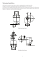
ASiSA
AS-Interface Speed Alarm
USER’S MANUAL
����������
�����
�����
� �
�����
� �
���
6111 Blue Circle Drive
Minnetonka, MN 55343
Phone: 952.930.0100
Fax: 952.930.0130
ISO 9001:2000 Certified
�����
Free Catalog and Application Assistance
1.800.328.6170
Visit Us Online
www.electro-sensors.com
990-002800 Revision C
Description
ASiSA continuously monitors rotating shaft speed, comparing it to a trip-point setting and alarming when less than the
trip-point. The ALARM state is accessible over AS-Interface communications and visibly indicated by the internal
ALARM led.
The rugged unit requires a shaft-mounted magnetic pulser target (disc or wrap) such as the model 255 pulser disc
(included). The rotating pulser target produces an alternating magnetic signal at ASiSA’s stationary sensing head. The
signal frequency varies in direct linear proportion to the rotating target’s rpm. ASiSA senses this frequency and compares
it to the TRIP-POINT setting.
When the frequency falls below the TRIP-POINT setting, ASiSA is alarmed.
When the frequency exceeds the TRIP-POINT setting, ASiSA is not-alarmed.
Measurable Speed Range
The ASiSA TRIP-POINT frequency is adjustable within the range:
0.53 → 27 Hz.
The frequency (f) to RPM conversion is given by the formula: RPM = f * 60 / PPR
Where f is in Hz (pulses per second) and PPR is pulser target pulses-per-revolution.
Since RPM changes inversely with PPR, increasing PPR scales TRIP-POINT RPM range down:
Pulser Target
Corresponding TRIP-POINT RPM range
Model 256 Pulser Disc (4 PPR)
8.0 → 400
Model 255 Pulser Disc (8 PPR)
4.0 → 200
Custom Pulser Wrap (16 PPR)
2.0 → 100
AS-Interface
Profile
S-B.A.E (A/B slave free profile, I/O code B)
AS-Interface Parameter bits
P3
(master Write Parameter info)
AS-Interface I/O Data bits
P2
P1
P0
unused
unused
unused
D2
D1
D0
unused
unused
D3
Output (master Data Exchange req. info)
ALARM unused (1)
Input (slave Data Exchange resp. info)
ALARM (D3) polarity
1 (Alarmed) - speed less than TRIP POINT setting
0 (Not Alarmed) - speed greater than TRIP POINT setting
LEDs
LED
ON
OFF
ALARM
Alarmed
Not Alarmed
POWER
Receiving Power
Not Receiving Power
ASi (status)
Communication OFF
Communication ON
2
Mechanical installation
ASiSA may be mounted on rigid conduit or with the mounting bracket assembly (provided).
The gap (A) between the sensing head and the Pulser Disc/Wrap must be 1/16 to 1/4 inch.
The center line of the magnets (B) must align with the center of the sensing head as the Pulser Disc/Wrap rotates.
Remove the round cover from the housing and pull AS-Interface network cable through the conduit port into the
enclosure. Connect the 2 cable wires to the terminal plug.
B
A
With Pulser Disc Target
�
A
A
With Pulser Wrap Target
3
Setting the TRIP-POINT
With network power applied and the shaft turning at normal operating speed, slowly turn the TRIP-POINT potentiometer
clockwise until the ALARM led turns on. Then slowly turn the TRIP-POINT potentiometer counter-clockwise until the
ALARM led turns off. How far below this point you set the TRIP-POINT will determine how far below the current shaft
speed the ASiSA will alarm. Firmly screw the round cover back onto the housing for normal use.
Specifications
Connector
2-conductor “phoenix-style” terminal plug
Power (network supplied)
20 → 31.6 Vdc, 30 mA maximum
TRIP-POINT
Potentiometer (single-turn, 280°, linear response)
0.53 → 27 Hz
(4.0 → 200 rpm with 8 PPR disc/wrap)
Setting
Range
LED indicators
AS-Interface
ALARM (red), POWER (green), ASi status (red)
Specification
Extended (A/B) addressing
Profile
V2.11
Yes
S-B.A.E
Airgap (sensing head to Disc/Wrap)
1/16 → 1/4 inch (2 → 6 mm)
Operating temperature
-25 → +85 °C (-13 → +185 °F)
Enclosure hazardous locations ratings
Weight
Class I, Div 1, Group C, D
Class II Groups E, F, G
UL File: E249019
(with bracket)
2.45 Lb (1.11 kg)
Dimensions (with bracket)
(in inches)
1.84
4.40
0.25
1.38
4.81
3.90
4.00
2.38
1" NPT
1.250
0.260
2.750
1.630
0.560
0.316
4