1
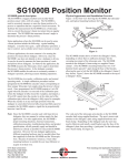
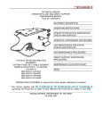
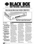
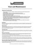
SG1000C Single-Turn Position Monitor
SG1000C general description
The SG1000C is a rugged, medium cost encoder-based
position sensor with a 4-20 mA output. The SG1000C is used
to accurately measure or sense the position of a process or
operation that has a repetitive single-turn rotary movement
(sensing a rotary position anywhere from 0° to 360°).
The SG1000C was developed for use as a Grain Distributor
Position Monitor (sensing the position of the distributor’s
chute). However, the SG1000C can also be used in other
applications where a single-turn position needs to be monitored.
The SG1000C has two modes: calibration mode, and normal
operating mode. A simple calibration procedure teaches
(programs) the SG1000C the encoder value corresponding to the
‘home’ (0°) position. Once programmed the SG1000C outputs:
• A 4 mA DC signal when the encoder is at the 0° home
position (a.k.a. the 0% position).
• A 20 mA DC signal when the encoder is at the 359° full
single-turn position (a.k.a. the 100% position). (Note: The
full-turn position is at 359° and not 360°, since 360° is a
complete wrap-around resulting in 0° again).
• Any mid-span encoder position between 0° and 359° is
represented by the output signal being proportionally between
4 and 20 mA.
Note: Since the SG1000C was developed for use as a Grain
Distributor Position Monitor, this user manual is
written mainly for that application. For other singleturn applications, the SG1000C’s proper mounting
locations, electrical connections, calibration procedure,
troubleshooting hints, and product specifications, all still
generally apply and should be followed as closely as
possible for successful SG1000C operation. However
for other applications, different mounting hardware may
be needed than shown. Because of numerous variances,
if other mounting hardware is needed the user must
fabricate or acquire it on their own.
The SG1000C attaches to the process’s single-turn shaft
using an “end-of-shaft” mounting method. See Figure 2. The
SG1000C’s encoder-shaft-end screws into a single 3/8-inch
diameter hole, to a depth of 0.625 inch, having 3/8” – 16 UNC2B threads.
Even though the SG1000C is mounted to the process shaft via
the “end-of-shaft” mounting method, installation of flexible
conduit and of the optional stabilizer bracket is recommended,
which allows the SG1000C to “float” along with any wobble
of the process’s shaft while still preventing the SG1000C from
rotating along with that shaft (see Fig. 2).
Note: The stabilizer bracket’s U-bolt is slightly oversized
to provide about 1/8” of slack between it and the
SG1000C. The U-bolt’s slack prevents it from
rigidly clamping to the SG1000C’s conduit port.
�������
�������������
������������������
�����������������
��������
�������
��������������������
Figure 2:
Electrical connections
The SG1000C’s electrical cable has three wires, plus a shieldwire. Connect as follows: (See Figure 3):
�������
�������
����������
�
���
Physical Appearance and Installation Overview
������
������������
Figure 1 is the front-view of the SG1000C, showing the encoderoutput-shaft.
���
�
� �
�
������������
������
������
���������
����������
��������
�����
Figure 3:
�����
�������������
����������������������
Figure 1:
6111 Blue Circle Drive
Minnetonka, MN 55343
Phone: 952.930.0100
Fax: 952.930.0130
ISO 9001:2000 Certified
•
•
•
•
Connect the shield wire to the earth ground.
Connect the black wire to the power-supply (-) terminal.
Connect the red wire to the power-supply (+24 Vdc)
terminal.
Connect the clear wire to a resistive load of 250 Ω to
500 Ω, (usually this load is internal to a PLC, etc.).
Free Catalog and Application Assistance
1.800.328.6170
Visit Us Online
www.electro-sensors.com
990-002420 Revision D
•
Note: The clear wire is the 4-20 mA DC output line.
The other side of the 250 Ω to 500 Ω load must be
connected to the power-supply (-) terminal.
See Figure 4 below for related information.
enclosure, and not the encoder-shaft-end of the enclosure:
•
If the encoder shaft turns in the CW direction as the
process’s shaft is turned from the 0° home to the 359°
full-turn position, then set SW1 to the OFF position (i.e.,
toward the center of the PC board). See Figure 4.
•
If the encoder shaft turns in the CCW direction as the
process’s shaft is turned from the 0° home to the 359°
full-turn position, then set SW1 to the ON position (i.e.,
toward the edge of the PC board). See Figure 4.
Calibration Procedure
Calibration consists of teaching the SG1000C the encoder
value for the 0° ‘home’ position. (Note: After being taught the
encoder value for the 0° ‘home’ position, the SG1000C then
automatically figures the encoder value for the 359° full singleturn position as per the CW/CCW direction set by Var01).
Note: The direction switch SW1 is monitored only briefly
during a calibration power-up (i.e., calibration switch
SW2 pressed-in while applying +24 Vdc to the unit).
After the unit powers-up and is in calibration mode,
SW1 is no longer relevant. Hence, changing SW1 at
this point has no effect. Because of this, SW1 must
be set to the desired position before the +24 Vdc
power is applied to the unit in order for the calibration
power-up to capture the desired setting of SW1.
The six calibration steps are as follows (once the user is familiar
with the calibration procedure they need only follow the
underlined portions as a quick calibration guide):
1) Remove (twist CCW) the back-end-cover from the
SG1000C.
This provides access to the edge of the SG1000C’s printed
circuit board, namely the direction switch SW1 (the slide
switch), and the calibration switch SW2 (the push-button
switch). See Figure 4 for locations of these switches.
CCW
3) Press-in the calibration switch SW2, then apply +24 Vdc
power to the SG1000C.
(Do not press SW2 multiple times or allow it to change state,
just keep it pressed-in). Continue to keep SW2 pressed-in
for a few seconds until the SG1000C outputs a constant 12
mA from its signal line, then release the button.
The SG1000C is now in the calibration mode.
CW
���
CW(OFF)
���
CCW(ON)
SW1 Detail
��
���
����
���
�����
�����
������
4) Move the SG1000C to the 0° home position.
Note: The SG1000C’s 0° ‘home’ calibration position should
be located in the ‘space’ between any two downspouts
of the Grain Distributor system (and NOT pointed at
any particular downspout since this ‘home’ position also
ends-up being the 20 mA to 4 mA rollover-point).
• If the 20 mA to 4 mA rollover-point occurs while
pointing at a downspout, then it could cause confusion
during normal operation if the chute positioning was
‘off’ by just one encoder count. That could cause
the SG1000C to indicate the chute as being at the 4
mA position when in reality it was still at the 20 mA
position (the difference being only one encoder count).
Hence, it is best to locate the 0° ‘home’ position at a
spot that is less critical to the 20 mA to 4 mA rolloverpoint, i.e., such as between downspouts.
Figure 4:
Note: Also on the edge of the PC board are two adjustment
potentiometers, R7 and R8, and a 3-pin terminal TB1.
Pot R7 is for tweaking the 4 mA output level. Pot R8 is
for tweaking the 20 mA output level. These two pots are
factory-adjusted, and the user normally should not have to
adjust them. It is best to leave these two pots alone.
The user normally should not have to disconnect the
3-wire cable from the SG1000C. But if they do so, they
must reconnect the 3-wire cable to the SG1000C as
follows:
• +24Vdc red wire to TB1-1.
• 4-20mA signal clear wire to TB1-2.
• Power supply ground black wire to TB1-3.
5) Press the calibration switch SW2.
• This captures the present encoder count. This value is
then used for the 0° home position.
• The SG1000C then automatically exits the calibration
mode and enters the normal operating mode.
Note: The calibration mode is exited at this point for both
valid and invalid calibrations.
For a valid calibration: If the user does not
2) Before applying +24 Vdc power to the SG1000C, set the
direction switch SW1 on the SG1000C’s PC board to the
proper position for the application.
SW1 tells the SG1000C the direction the encoder turns, CW
or CCW, as the process’s shaft is turned from the 0° home
to the 359° full-turn position. The CW or CCW direction is
defined via the viewer looking at the back-cover-end of the
2-4
Free Catalog and Application Assistance
1.800.328.6170
Website: www.electro-sensors.com
990-002420 Revision D
immediately turn the shaft, then the output signal is
4 mA. (Because the shaft was left in the 0° home
position from step 5, the output signal is at 0%,
which is 4 mA).
For an invalid calibration: The output signal
remains at 12 mA.
See the “Valid Calibration” and “Invalid Calibration”
sections below for details regarding whether, or not, your
SG1000C accepted the process’s calibration position.
If re-calibration is needed, see the section below titled
“How to clear-out the existing calibration and
reprogram the SG1000C.”
Invalid Calibration (Error condition behavior)
Assuming the user followed the calibration process incorrectly,
the SG1000C behaves as follows:
• The output signal remains at a constant 12 mA after the
calibration mode is automatically exited.
6) Replace the back-end-cover onto the SG1000C.
This ends the calibration procedure.
Power-ups; calibration vs. normal operating mode
•
Valid Calibration (Normal Operating Behavior)
Assuming the user followed the calibration process correctly,
the SG1000C behaves as follows:
• When the shaft is at the 0° home position (i.e., the 0%
position) the output signal is 4 mA.
• When the shaft is at the 359° full-turn position (i.e., the 100%
position) the output signal is 20 mA.
• Any mid-span position between 0° and 359° is represented by
the output signal being proportionally between 4 and 20 mA
(i.e., proportionally between 0% and 100%).
•
An SG1000C that is un-calibrated (or if the calibration
attempt was invalid) automatically powers-up in the
calibration mode, the next time power is applied.
A properly calibrated SG1000C powers-up in the normal
operating mode, when power is applied.
Troubleshooting Hints
As an aid to troubleshooting, see figure 3 on how to connect an
ammeter to directly measure the 4-20mA output signal.
1) If your SG1000C outputs a 4 mA to 20 mA signal, but not at
the shaft positions expected, then double-check the following:
A) Before you performed the calibration procedure, did you
set the direction switch SW1 to the proper position (CW
or CCW) before applying power to the SG1000C.
B) Did you program the SG1000C at your desired 0° home
position?
C) Is your SG1000C terminal TB1 wiring correct?
• +24Vdc red wire is TB1-1.
• 4-20mA signal clear wire is TB1-2.
• Power supply ground black wire is TB1-3.
D) Assuming conditions (A), (B), and (C) are proper, and
your SG1000C still seems to behave improperly, then
try re-calibrating again, paying close attention to the six
calibration steps.
Note: Since the SG1000C is designed to monitor one full
single-turn of shaft rotation, theoretically this results in
no 0% or 100% run-out zones left-over on either end of
the rotary sweep (i.e., once the 359° full-turn position is
reached, any further movement results in an immediate
rollover to the 0° home position).
However to make the the hardware calibration of the
R7 and R8 potentiometers easier, there is a two-encoder
count plateau at the 0° home position, and a two-encoder
count plateau at the 359° full-turn position.
This means:
• the SG1000C signals 4 mA for both the 0° home
position as well as for one encoder count after the 0°
home position.
• the SG1000C signals 20 mA for both the 359° full-turn
position as well as one encoder count before the 359°
full-turn position.
2)
• For a properly calibrated SG1000C, the direction of
calibration (CW or CCW), and the encoder values for the 0°
home and 359° full-turn shaft positions are all stored in the
SG1000C’s EEPROM memory.
Note: Since a properly calibrated SG1000C can never enter the
calibration mode again by itself after the calibration mode
is exited, the direction switch SW1 and the calibration
switch SW2 are ignored (during normal operating mode).
This means that for a properly calibrated SG1000C
the calibration results are protected from the user
inadvertently changing the SW1 position, or by pressing
SW2 (during normal operating mode).
3-4
If you have gone through troubleshooting hints (1A), (1B),
(1C), and (1D), and if your SG1000C seems to otherwise
respond properly, from 0° to 359° of rotation, with the only
exception being that strange values other than 4 mA and
20 mA are output for the positions (e.g., 3 mA at 0° home
position and 23 mA at the 359° full-turn position), then
possibly the R7 and R8 factory potentiometer settings have
been tampered with. See Figure 4 for location of these
pots.
Evidence of R7 and R8 tampering is most easily seen when
in the calibration mode. When R7 and R8 are at their
factory-settings, the output signal is 12 mA during
calibration mode. (Recall that the output signal remains
at 12 mA until the calibration process is completed). If
during calibration mode the output signal is not 12 mA,
then most likely the R7 and R8 factory-settings have been
tampered with.
Free Catalog and Application Assistance
1.800.328.6170
Website: www.electro-sensors.com
990-002420 Revision D
Troubleshooting Hints (cont.)
Mechanical packaging
• Mounts on “end-of-shaft” via single 3/8-inch diameter hole,
to a depth of 0.625 inch, and 3/8 “– 16 UNC threads.
• Cylindrical aluminum housing / cover. Outside diameter of 311/16th inch. Maximum length of 7-5/8th inch (length includes
cover and encoder shaft).
• The stabilizer bracket can be semi-rigidly mounted to the
application’s framework using two user supplied 5/16”
diameter bolts.
Environmental considerations
If you feel confident that you have followed the calibration
procedure properly (perhaps have done it several times
over), and followed the troubleshooting hints in (1A),
(1B),(1C), and (1D), AND you still see strange values
other than 4 mA at 0° ‘home’ and 20 mA at the 359° fullturn, then you can attempt to restore R7 and R8 to the
factory-settings by doing the following: (This assumes
you have already calibrated your SG1000C for the 0° home
position).
A) During normal operating mode, move the shaft to your
0° home position. Adjust R7 until 4 mA is output from
the signal line.
B) During normal operating mode, move the shaft to
the 359° full-turn position. Adjust R8 until 20 mA is
output from the signal line.
C) You can now test and verify that your R7 and R8 are
indeed set back to factory settings. Do this by reentering the calibration procedure (press-in SW2, then
apply power). If the 4 mA to 20 mA output signal is at
12 mA (or fairly close) when in the calibration mode,
then you have properly restored R7 and R8 settings.
D) Continue and complete the calibration procedure for
the shaft’s 0° home position.
Class I, Div 1, Groups C, D
Class II, Div 1, Groups E, F, G
UL File: E249019
• NEMA4X Cast Aluminum Housing
• Temperature range of -40ºC to +65ºC (-40ºF to 149ºF).
• Humidity range of 0% to 90% non-condensing.
Operator interface
• One pushbutton: (enter calibration mode upon power-up,
calibrate for 0° home position).
• One slide switch: (select calibration direction CW/CCW).
Operation modes
• Normal Operating Mode: (output 4 mA to 20 mA signal
corresponding to shaft position).
• Calibration Mode: (select calibration direction, calibrate for
0° home shaft position).
How to clear-out the existing calibration, and
reprogram the SG1000C
First remove +24Vdc power, then press and hold-in the SW2
button while re-applying the +24Vdc power to the SG1000C.
Continue to keep the SW2 button pressed-in for a few seconds
until the SG1000C outputs 12 mA, then release the SW2 button.
The old calibration has now been cleared-out, and the SG1000C
is in calibration mode awaiting new calibration. See the
“Calibration Procedure” section for complete details.
I/O requirements
• Input: External power supply of +24 Vdc (± 10%). The
SG1000C’s current draw is 40 mA DC or less
• Output: 12 mA DC output signal for an un-calibrated system
(when running in Calibration Mode, or in Normal Operating
Mode with improper calibration).
• Output: 4 mA DC to 20 mA DC output signal proportional
to shaft position, for a properly calibrated system running in
Normal Operating Mode.
Specifications
Performance
• The SG1000C’s built-in 9-bit absolute encoder measures shaft
position (internal readings are 0 up to 511 counts).
• The SG1000C uses a 1:1 gear-ratio between the output-shaft
and the encoder.
• The SG1000C’s 4-20 mA output signal resolution is 0.2%,
and is updated once every 7 msec. (0.2% is 1 encoder count
out of 512 counts).
• Since the 4-20 mA output spans 16 mA, a 0.2% resolution
gives an incremental change of 0.032 mA (16mA x 0.002).
• The SG1000C’s maximum mechanical rated speed is 200
RPM.
• In the event of power failure or shutdown, the EEPROM
retains the shaft calibration direction (CW, CCW), and shaft
calibration positions (0° home, 359° full-turn).
Additional Information
To get additional information about the SG1000C, visit our
website at: www.electro-sensors.com
Notice:
Copyright © 2009 Electro-Sensors, Inc. All rights reserved. No part
of this document can be duplicated or distributed without the express
written permission of Electro-Sensors, Inc.
While the information in this manual has been carefully reviewed for
accuracy, Electro-Sensors, Inc. assumes no liability for any errors or
omissions in the information. Electro-Sensors, Inc. reserves the right
to make changes without further notice to any part of this manual or
product described in this manual.
4-4
Free Catalog and Application Assistance
1.800.328.6170
Website: www.electro-sensors.com
990-002420 Revision D