1
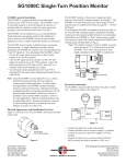
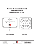
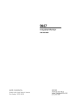
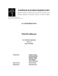
SG1000B Position Monitor
SG1000B general description
The SG1000B is a rugged, medium cost encoder-based
position sensor with a 4-20 mA output. The SG1000B is
used to accurately measure or sense the linear position of a
process or operation that has a repetitive linear movement. To
facilitate this measurement the SG1000B uses a TelescopicArm to convert the process’s linear movement into an angular
movement. The SG1000B then measures the arm’s angle to
determine the process’s linear position.
Physical Appearance and Installation Overview
Figure 1 is the front-view showing the SG1000B, the telescopicarm, and typical mounting hardware for both.
�������
��������������
�����������������
�������������
Some applications where the SG1000B can be used to sense
a linear position include the following: a grain handling
slidegate; a security fence gate; a pick-and-place operation; a
louver control; and a cylinder arm’s linear extension or reach.
Of these applications, the most common is for sensing the
position of a linear driven slidegate. (However, since the
SG1000B’s use does not depend on how a slidegate is driven,
it can also be used to measure the linear position of a rackand-pinion driven slidegate). In whatever the application, the
SG1000B measures the Telescopic-Arm’s angle to determine
the process’s linear position. In the slidegate example,
the SG1000B enables the end-user to accurately monitor a
slidegate’s position, allowing accurate blending operations.
The SG1000B has two modes: calibration mode, and normal
operating mode. A simple calibration procedure teaches
(programs) the SG1000B the encoder values corresponding to
three unique Telescopic-Arm angles along the process’s linear
travel. Once programmed, the SG1000B outputs a 4 mA DC
signal when the encoder is at one-end of the calibration span
(when the slidegate is fully-closed for example), and outputs a
20 mA DC signal when the encoder is at the other-end of the
calibration span (when the slidegate is fully-open for example).
When the encoder is at any mid-span position (when the
slidegate is somewhere between fully-closed and fully-open for
example), the SG1000B outputs a signal that is proportionally
between 4 and 20 mA.
Note: Since the SG1000B is mostly used with linear driven
slidegates, this user manual is written mainly for that
application. For other applications, the SG1000B’s
proper mounting locations, electrical connections,
calibration procedure, troubleshooting hints, and product
specifications, all still generally apply and should be
followed as closely as possible for successful SG1000B
operation. However for non-slidegate applications,
different mounting hardware may be needed (other than
that supplied) for both the SG1000B and the TelescopicArm. Because of numerous variances, if such other
mounting hardware is needed the user must fabricate or
acquire it on their own.
6111 Blue Circle Drive
Minnetonka, MN 55343
Phone: 952.930.0100
Fax: 952.930.0130
ISO 9001:2000 Certified
�����������������
Figure 1:
The SG1000B mounts above or below the slidegate’s frame,
depending on where there is sufficient clearance for the
sweeping movement of the telescopic-arm. The SG1000B
mounts to the slidegate’s frame using two supplied ‘beam
clamps’. (The SG1000B’s mounting bracket has two 5/16”
diameter holes spaced 2” apart along the base of the bracket,
allowing the user to bolt the SG1000B to the slidegate’s frame if
they desire). Figure 2 shows the SG1000B mounted to the top of
a slidegate’s frame.
�������������
�������
������������
�����
��������
Figure 2:
The wide-end of the telescopic-arm attaches to the SG1000B
encoder shaft using supplied hardware. The arm’s narrow-end
attaches to the slidegate’s plate using supplied hardware and
beam clamp. Depending on the slidegate used, the user may
need to fabricate and install a small bracket onto the face of the
slidegate’s plate, thus providing a ‘grab-point’ for the telescopicarm’s beam-clamp. See figure 3a.
Free Catalog and Application Assistance
1.800.328.6170
Visit Us Online
www.electro-sensors.com
990-002410 Revision F
is centered evenly between the two springs on the telescopicarm mounting hardware (this lessens stress on the telescopicarm). Re-tighten the carriage bolts when finished. See Figure 5.
�������
��������������
��������
��������
���������
�����
����
�����������
����
��������������
����������
�������
������������
���������������
�������
��������
��������
Figure 3a:
Figure 5:
Or, if there is clearance between the slidegate’s frame and plate
when the gate is fully-open, the telescopic-arm’s mounting
hardware stud can be reconfigured with the beam-clamp, thus
allowing the beam-clamp to directly grab the plate’s edge. See
figure 3b.
Electrical connections
The SG1000B’s electrical cable has three wires, plus a shieldwire. Connect as follows: (See Figure 6):
�������
�������
����������
�
���
������
������������
���������
�����
���
�
Figure 3b:
� �
There are some limitations as to where the SG1000B can be
mounted along the perimeter of the slidegate’s frame. The
SG1000B must be mounted within the end-points of the sliding
plate’s linear travel. See Figure 4 for examples of valid and
invalid mounting positions. (Figure 4 shows the slidegate in the
fully-closed position, i.e, 0% open).
�������
�������
������
������
���������
����������
��������
�����
Figure 6:
•
•
•
•
�������
�����
���� ����
�
������������
����
�������
•
Connect the shield wire to the earth ground.
Connect the black wire to the power-supply (-) terminal.
Connect the red wire to the power-supply (+24 Vdc)
terminal.
Connect the clear wire to a resistive load of 250 Ω to
500 Ω, (usually this load is internal to a PLC, etc.).
Note: The clear wire is the 4-20 mA DC output line.
The other side of the 250 Ω to 500 Ω load must be
connected to the power-supply (-) terminal.
See Figure 7 below for related information.
�������
�������������
����������������
������
����
�������������
������������������
Figure 4:
The SG1000B mounting bracket has some vertical adjustment
capability. After the SG1000B has been mounted on the
slidegate frame, if need be loosen the two 5/16” diameter
carriage bolts holding the two bracket halves together, and set
the height of the bracket so the narrow-end of the telescopic-arm
2-6
Free Catalog and Application Assistance
1.800.328.6170
Website: www.electro-sensors.com
990-002410 Revision F
Calibration Procedure
•
Calibration consists of teaching the SG1000B the encoder
values for the following three telescopic-arm positions:
- arm perpendicular to the gate’s linear travel direction.
- arm with slidegate fully-closed (i.e., 0% open).
- arm with slidegate fully-open (i.e., 100% open).
The 10 calibration steps are as follows (once the user is familiar
with the calibration procedure they need only follow the
underlined portions as a quick calibration guide).
Note: The direction switch SW1 is monitored only briefly
during a calibration power-up (i.e., calibration switch
SW2 pressed-in while applying +24 Vdc to the unit).
After the unit powers-up and is in calibration mode,
SW1 is no longer relevant. Hence, changing SW1 at
this point has no effect. Because of this, SW1 must
be set to the desired position before the +24 Vdc
power is applied to the unit in order for the calibration
power-up to capture the desired setting of SW1.
1) Remove (twist CCW) the back-end-cover from the
SG1000B.
This provides access to the edge of the SG1000B’s printed
circuit board, namely the direction switch SW1 (the slide
switch), and the calibration switch SW2 (the push-button
switch). See Figure 7 for locations of these switches.
CCW
3) Press-in the calibration switch SW2, then apply +24 Vdc
power to the SG1000B.
(Do not press SW2 multiple times or allow it to change state,
just keep it pressed-in). Continue to keep SW2 pressed-in
for a few seconds until the SG1000B outputs a constant 12
mA from its signal line, then release the button.
The SG1000B is now in the calibration mode.
CW
���
CW(OFF)
���
CCW(ON)
SW1 Detail
��
���
����
���
�����
�����
4) Run the gate to the position that places the TelescopicArm in a perpendicular 90° position to the gate’s linear
travel direction. See Figure 8.
Note: If the slidegate drive system does not allow the user the
ability to control the slidegate precisely enough so as to
place the telescopic-arm perpendicular to the direction
of travel, then the user can instead do the perpendicular
calibration point by first detaching the narrow-end
of the arm from the slidegate’s plate (by loosening
the small beam clamp) and manually setting the arm
perpendicular to the travel direction.
������
Figure 7:
Note: Also on the edge of the PC board are two adjustment
potentiometers, R7 and R8, and a 3-pin terminal TB1.
Pot R7 is for tweaking the 4 mA output level. Pot R8 is
for tweaking the 20 mA output level. These two pots are
factory-adjusted, and the user normally should not have to
adjust them. It is best to leave these two pots alone.
The user normally should not have to disconnect the
3-wire cable from the SG1000B. But if they do so, they
must reconnect the 3-wire cable to the SG1000B as
follows:
• +24Vdc red wire to TB1-1.
• 4-20mA signal clear wire to TB1-2.
• Power supply ground black wire to TB1-3.
�������
���
2) Before applying +24 Vdc power to the SG1000B, set the
direction switch SW1 on the SG1000B’s PC board to the
proper position for the application.
SW1 tells the SG1000B the direction the encoder turns,
CW or CCW, as the gate is moved from the fully-closed
to the fully-open position. The CW or CCW direction is
defined via the viewer looking at the back-cover-end of the
enclosure, and not the encoder-shaft-end of the enclosure:
•
If the encoder shaft turns in the CCW direction as the
gate is moved from the fully-closed to the fully-open
position, then set SW1 to the ON position (i.e., toward
the edge of the PC board). See Figure 7.
Figure 8:
5) Press the calibration switch SW2.
• This captures the present encoder count. This value is then
used for the telescopic-arm at perpendicular position.
• The output signal remains at 12 mA.
• Reattach arm after step 5 (if removed in step 4).
If the encoder shaft turns in the CW direction as the gate
is moved from the fully-closed to the fully-open position,
then set SW1 to the OFF position (i.e., toward the center
of the PC board). See Figure 7.
3-6
Free Catalog and Application Assistance
1.800.328.6170
Website: www.electro-sensors.com
990-002410 Revision F
Calibration Procedure (Cont.)
calibrated position, then the encoder “wraps-around” and the
output signal jumps to the fully-open calibrated value of 20
mA.
• If the gate is moved to a position that is slightly beyond
(outside of) the fully-open (100% open) calibrated position,
then the output signal remains at 20 mA. This is known as
100% ‘run-out’ , and it holds up to a certain point. If the
encoder is turned far enough beyond the fully-open (100%
open) calibrated position, then the encoder “wraps-around”
and the output signal jumps to the fully-closed calibrated
value of 4 mA.
• For a properly calibrated SG1000B, the direction of
calibration (CW or CCW), and the encoder values for the arm
at perpendicular, fully-closed, and fully-open gate positions
are all stored in the SG1000B’s EEPROM memory.
6) Move the gate to the fully-closed position (0% open).
7) Press the calibration switch SW2.
• This captures the present encoder count. This value is
then used for the fully-closed position (0% open).
• The output signal remains at 12 mA.
8) Move the gate to the fully-open position (100% open).
Note: As the gate moves from fully-closed to fully-open, the
SG1000B’s encoder shaft must turn at least 1/64th of a
turn, but not more than 0.36 of a turn. Or seen another
way, as the gate moves from fully-closed to fullyopen, the telescopic-arm must swing at least 5.6°, but
not more than 130°. Hence, if the arm swings more
than 130°, or less than 5.6°, then the SG1000B will
not properly work for the application.
Note: Since a properly calibrated SG1000B can never enter the
calibration mode again by itself after the calibration mode
is exited, the direction switch SW1 and the calibration
switch SW2 are ignored (during normal operating mode).
This means that for a properly calibrated SG1000B
the calibration results are protected from the user
inadvertently changing the SW1 position, or by pressing
SW2 (during normal operating mode).
If re-calibration is needed, see the section below titled
“How to clear-out the existing calibration and
reprogram the SG1000B.”
9) Press the calibration switch SW2.
• This captures the present encoder count. This value is
then used for the fully-open position (100% open).
• The SG1000B then automatically exits the calibration
mode and enters the normal operating mode.
Note: The calibration mode is exited at this point for both
valid and invalid calibrations.
For a valid calibration: If the user does not
immediately move the gate, then the output signal
is 20 mA. (Because the gate was left in the fullyopen position from step 8, the output signal is at
100%, which is 20 mA).
For an invalid calibration: The output signal
remains at 12 mA.
See the “Valid Calibration” and “Invalid Calibration”
sections below for details regarding whether, or not, your
SG1000B accepted the gate’s three calibration positions.
Invalid Calibration (Error condition behavior)
Assuming the user followed the calibration process incorrectly,
the SG1000B behaves as follows:
• The output signal remains at a constant 12 mA after the
calibration mode is automatically exited.
An “invalid calibration” is most likely due to one of the
following:
- If the user did not move the gate (or moved it but less than
a 5.6º swing of the arm) between teaching the SG1000B
the fully-closed and fully-open positions, then the closed
and open positions have the same (or nearly the same)
encoder count.
- The user accidentally “double-pressed” SW2 either
during power-up or then while teaching the SG1000B the
perpendicular or the fully-closed positions.
10)Replace the back-end-cover onto the SG1000B.
This ends the calibration procedure.
Valid Calibration (Normal Operating Behavior)
Assuming the user followed the calibration process correctly,
the SG1000B behaves as follows:
• When the gate is at the fully-closed position (0% open), the
output signal is 4 mA.
• When the gate is at the fully-open position (100% open), the
output signal is 20 mA.
• Any gate position between 0% open and 100% open is
represented by the output signal being proportionally between
4 mA and 20 mA.
• If the gate is moved to a position that is slightly beyond
(outside of) the fully-closed (0% open) calibrated position,
then the output signal remains at 4 mA. This is known as 0%
‘run-out’ , and it holds up to a certain point. If the encoder
is turned far enough beyond the fully-closed (0% open)
Power-ups; calibration vs. normal operating mode
•
•
4-6
An SG1000B that is un-calibrated (or if the calibration
attempt was invalid) automatically powers-up in the
calibration mode, the next time power is applied.
A properly calibrated SG1000B powers-up in the normal
operating mode, when power is applied.
Free Catalog and Application Assistance
1.800.328.6170
Website: www.electro-sensors.com
990-002410 Revision F
Troubleshooting Hints
As an aid to troubleshooting, see figure 6 on how to connect an
ammeter to directly measure the 4-20mA output signal.
1) If your SG1000B outputs a 4 mA to 20 mA signal, but not at
the gate positions expected, then double-check the following:
A) Before you performed the calibration procedure, did you
set the direction switch SW1 to the proper position (CW or
CCW) before applying power to the SG1000B.
B) As your gate moves from fully-closed to fully-open, does
the SG1000B’s telescopic-arm swing more than 130º, or
less than 5.6º? If so, then the SG1000B will not work in
your application.
C) Is your SG1000B terminal TB1 wiring correct?
• +24Vdc red wire to TB1-1.
• 4-20mA signal clear wire to TB1-2.
• Power supply ground black wire to TB1-3.
D) Assuming conditions (A), (B), and (C) are proper, and
your SG1000B still seems to behave improperly, then
try re-calibrating again, paying close attention to the ten
calibration steps.
2)
indeed set back to factory settings. Do this by reentering the calibration procedure (press-in SW2, then
apply power). If the 4 mA to 20 mA output signal is at
12 mA (or fairly close) when in the calibration mode,
then you have properly restored R7 and R8 settings.
D) Continue and complete the calibration procedure for
the arm’s perpendicular, fully-closed and fully-open
positions.
How to clear-out the existing calibration, and
reprogram the SG1000B
First remove +24Vdc power, then press and hold-in the SW2
button while re-applying the +24Vdc power to the SG1000B.
Continue to keep the SW2 button pressed-in for a few seconds
until the SG1000B outputs 12 mA, then release the SW2 button.
The old calibration has now been cleared-out, and the SG1000B
is in calibration mode awaiting new calibration. See the
“Calibration Procedure” section for complete details.
If you have gone through troubleshooting hints (1A), (1B),
(1C), and (1D), and if your SG1000B seems to otherwise
respond properly, from fully-closed to fully-open, with
the only exception being that strange values other than 4
mA and 20 mA are output for the fully-closed/fully-open
positions (e.g., 3 mA at one-end and 23 mA at the otherend), then possibly the R7 and R8 factory potentiometer
settings have been tampered with. See Figure 7 for location
of these pots.
Evidence of R7 and R8 tampering is most easily seen
when in the calibration mode. When R7 and R8 are at
their factory-settings, the output signal is 12 mA during
calibration mode. (Recall that the output signal remains at
12 mA until the calibration process is completed). If during
calibration mode the output signal is not 12 mA, then most
likely the R7 and R8 factory-settings have been tampered
with.
If you feel confident that you have followed the calibration
procedure properly (perhaps have done it several times
over), and followed the troubleshooting hints in (1A),
(1B),(1C), and (1D), AND you still see strange values other
than 4 mA at one end and 20 mA at the other, then you
can attempt to restore R7 and R8 to the factory-settings
by doing the following: (This assumes you have already
calibrated your SG1000B for the arm at perpendicular,
fully-closed, and fully-open gate positions).
A) During normal operating mode, move the gate to your
fully-closed calibrated position. Adjust R7 until 4 mA
is output from the signal line.
B) During normal operating mode, move the gate to the
fully-open calibrated position. Adjust R8 until 20 mA is
output from the signal line.
C) You can now test and verify that your R7 and R8 are
5-6
Free Catalog and Application Assistance
1.800.328.6170
Website: www.electro-sensors.com
990-002410 Revision F
Specifications
Performance
Because of numerous variances, if such other mounting
hardware is needed the user must fabricate or acquire it on
their own.
- The SG1000B’s built-in 9-bit absolute encoder measures
the telescopic-arm position (internal readings are 0 up to 511
counts).
- The SG1000B uses a 1:2.75 gear-ratio on the output-shaft of
the encoder.
- The maximum calibrate-able span is 0.36 turns of the output
shaft (or a 130º swing of the telescopic-arm).
- The minimum calibrate-able span is 1/64th turn of the output
shaft (or a 5.6º swing of the telescopic-arm).
- The SG1000B’s 4-20 mA output signal resolution depends
mostly on:
• The number of encoder counts in the calibration span for
the application’s end-to-end swing of the telescopic-arm.
• And the location of the telescopic-arm’s perpendicular
point in the calibration span.
Environmental considerations
Class I, Div 1, Groups C, D
Class II, Div 1, Groups E, F, G
UL File: E249019
- NEMA4X Cast Aluminum Housing
- Temperature range of -40ºC to +65ºC (-40ºF to 149ºF).
- Humidity range of 0% to 90% non-condensing.
Operator interface
- One pushbutton: (enter calibration mode upon power-up, and
calibrate for the three telescopic-arm positions).
- One slide switch: (select calibration direction, CW/CCW).
With these dependences, the SG1000B’s 4-20 mA resolution
varies from a best of 0.2% of the calibrated span (when
calibrated at the maximum span of 511 encoder counts), to a
worst of 5.0% of the calibrated span (when calibrated at the
minimum span of 21 encoder counts).
Since the 4-20 mA output has a 16 mA span, a 0.2%
resolution gives an incremental change of 0.032 mA, and a
5.0% resolution gives an incremental change of 0.800 mA.
Operation modes
- Normal Operating Mode: (output 4 mA to 20 mA signal
corresponding to the telescopic-arm position).
- Calibration Mode: (select calibration direction, calibrate for
the three telescopic-arm positions).
- When power is shutdown or fails, the EEPROM retains
the telescopic-arm calibration direction (CW, CCW), and
calibration positions (arm at perpendicular, arm at one end of
span, and arm at other end of span).
Mechanical packaging
- The SG1000B has a cylindrical aluminum housing / cover.
Outside diameter of 3-11/16th inch. Maximum length
of 7-5/8” (length includes cover and encoder shaft).
- The Telescopic-Arm is 1.8” wide at it widest.
Different arm lengths are available per application’s needs.
- For typical slidegate applications:
• The SG1000B mounts onto the slidegate frame using two
supplied ‘beam clamps’, or via two user supplied 5/16”
diameter bolts (length and thread-type chosen by user as
needed).
• The narrow-end of the Telescopic-Arm attaches to the
slidegate’s plate using supplied hardware and one beam
clamp (supplied). However, depending on the slidegate the
user may need to fabricate and install a small bracket onto the
face of the slidegate’s plate, thus providing a ‘grab-point’ for
the Telescopic-Arm’s beam clamp.
- For all applications, the wide-end of the Telescopic-Arm
attaches to the SG1000B using supplied hardware.
- For non-slidegate applications:
• Different mounting hardware may be needed (other than that
supplied) for both the SG1000B and the Telescopic-Arm.
I/O requirements
- Input: External power supply of +24 Vdc (± 10%). The
SG1000B’s current draw is 40 mA DC or less.
- Output: 12 mA DC output signal for an un-calibrated system
(when running in Calibration Mode, or in Normal Operating
Mode with improper calibration).
- Output: 4 mA DC to 20 mA DC output signal proportional
to telescopic-arm position, for a properly calibrated system
running in Normal Operating Mode.
Additional Information
Some common Telescopic-Arms used with the SG1000B are:
16” Arm: 800-010116
18” Arm: 800-010118
20” Arm: 800-010120
To get additional information about the SG1000B, visit our
website at: www.electro-sensors.com
The SG1000B and Telescopic-Arm have US Patent #7,191,527,
and US Patent #7,444,751.
Notice:
Copyright © 2009 Electro-Sensors, Inc. All rights reserved. No part
of this document can be duplicated or distributed without the express
written permission of Electro-Sensors, Inc.
While the information in this manual has been carefully reviewed for
accuracy, Electro-Sensors, Inc. assumes no liability for any errors or
omissions in the information. Electro-Sensors, Inc. reserves the right
to make changes without further notice to any part of this manual or
product described in this manual.
6-6
Free Catalog and Application Assistance
1.800.328.6170
Website: www.electro-sensors.com
990-002410 Revision F