1
ColorCalibration
Software for color calibration of Sony Aibo robots in a RoboCup environment
By
Jens Törner
Carl Axelsson
USER MANUAL
Table of contents
1. Introduction
1.1 Quickstart
3
3
2. Working with ColorCalibration
2.1 Toolbox
2.2 Image window
2.3 Menus
2.4 Image index
2.5 Color tables
2.6 Automatization
2.7 Preferences
5
5
6
6
7
7
8
9
3. Working with files
3.1 PGM file format
3.2 KJI file format
3.3 Color Table file format
3.4 Converting PGM files to KJI files
10
10
10
10
10
4. Using native segmentation code
4.1 Why use native code?
4.2 Compiling the code to work with ColorCalibration
11
11
11
2
1 Introduction
ColorCalibration is developed with a RoboCup
environment in mind but can be reconfigured for other
color calibration needs. It will let you calibrate a color
table for use with your Sony Aibo robot with little effort.
It provides powerful tools to view, modify and
automatize the calibration.
Previous experience with Sony Aibo robots, RoboCup
and Open-R programming is assumed throughout this
user manual.
If you are a first time user please browse through the
Quickstart section of this manual to get started as soon as
possible.
Thank you for choosing ColorCalibration.
1.1 Quickstart
Install the program files in a directory. Start up the
ColorCalibration program with:
java ColorCalibration
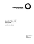
When the program is running, click the “Load” button in
the toolbox to open up the load file dialog. Select the
quickstart.kji image included in the ColorCalibration
distribution and click load. The image is loaded and
displayed as a thumbnail in the image index window at
the bottom of the screen. Single click on the image to
open it up in an image window. Your screen should now
look something like the screen pictured to the left.
Select some pixels from the ball by clicking on them in
the image window, and watch how the segment grows.
Select other colors from the toolbox and try to make the
segmented image as good as possible. If you make a
mistake, you can always click “Undo” to delete your last
selection. But remember that the undo function works
with channels, one for each color, so you have to be in
the right color in order to undo. There are twenty steps of
undo in each channel.
3
When you are satisfied with the segmentation, click the
“Save CT” button in the toolbox to save your color table.
Just press ok when the program asks for suffix.
ColorCalibration is so much more, but you should now
have a general idea of how to calibrate your Aibo!
4
2 Working with ColorCalibration
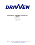
2.1 The Toolbox
Here you will find the most commonly used tools and
operations. The toolbox resides in a window of its own,
and can easily be placed anywhere on the screen you find
convenient.
Load – Opens the load image dialog which lets you select
and load one or more images from the hard drive or
directly from your Memory Stick reader. Images loaded
are displayed in the image index window on the bottom
of your screen.
Save CT – Opens the save color table dialog which lets
you specify a filename and path to save the color table.
You will be prompted for how to label the color table
arrays, just press ok to save it as “generic”. For more
information on the format color tables are saved in,
please see 3.3, Color Table file format.
Undo – Enables you to erase your last selected pixel from
your color table. Undo works with channels, so only
pixels selected in the color currently active is erased. To
undo a selection in another color, simply select that color
in the toolbox and press undo the desired number of
times. There are twenty steps of undo in each channel.
Please note that the results from undo will not be visible
until the image window is in focus. Undo effects all
images, not just the one(s) currently displayed.
Show Blobs – Checking this option displays all the
images in the index window as segmented. This is a great
way to get an overview of how good your color table is at
the moment. Please note that keeping this option checked
at all time might drastically reduce program performance.
Show In CT – Checking this option lets you click a pixel
in an image and see where in the color space it is located.
This is a powerful tool to find stray pixels in your color
table.
Color palette – Clicking on these selects which color you
are currently working with. The button is colored in the
5
active color. This also affects which undo channel is
used.
Threshold – This slider shows the threshold value for the
current color. Just drag it to change the threshold.
Thresholds affect how many pixels will be included when
growing the segments. Thresholds are saved with the
color table.
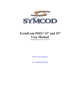
2.2 Image window
The image window is the main working window. In this
window you click to select pixels (color values) to be
included in your color table. The small display to the
right in the window shows the segmented version of the
image. Clicking on the buttons with arrows displays the
next/previous image.
2.3 Menus
The menus contain many options not available anywhere
else in ColorCalibration. There are five main categories:
File, Color Table, Options, Window and Help.
File – Images – Load – Opens the load image dialog
which lets you select and load one or more images from
your hard drive or directly from your Memory Stick
reader. Images loaded are displayed as thumbnails in the
image index window on the bottom of your screen. Single
click on a thumbnail to open it up in a new window.
File – Color Table – Load – Opens the load color table
dialog which lets you load a previously saved color table.
File – Color Table – Save – Opens the save color table
dialog which lets you specify a filename and path to save
your color table. You will be prompted for how to label
the color table arrays, just press ok to save it as “generic”.
For more information on the format color tables are saved
in, please see 3.3, Color Table file format.
File – Preferences – Opens the preferences dialog. For
more information on preferences settings, please see 2.7,
Preferences.
File – Exit – Exits the program.
6
Color Table – Modify – Opens the color table window.
This lets you see how the color values in your color table
are distributed in the color space. For more information
on how to work with the color table window, please see
2.5, Color Table.
Color Table – Reset – Resets the color table. Please be
careful with this function. You must undo for all the color
channels to get your color table back.
Options – Automatization – Opens the automatization
window. For more information on the automatization
process, please see 2.6, Automatization.
Window – Show Toolbox – Opens the toolbox window if
it is not already on open.
Window – Show Image Index – Opens a new image
index.
Help – Help – Shows this manual.
Help – About – Shows info about ColorCalibration.
2.4 Image index
The image index window shows small, thumbnail size,
versions of all images loaded. Images can be displayed as
regular images or segmented ones, based on the current
color table. Just check “Show Blobs” in the toolbox to
show segmented images. Please note that updating many
segmented images might drastically reduce program
performance.
2.5 Color table
The color table window shows how the color values in
the images loaded and in the current color table are
distributed in the YUV color space. There are 32 levels of
Y (light), which one is displayed is indicated by the
“light” slider. For each Y value, the U and V values in the
current color table are shown by a box in the color space
area. If the “show pixels” option is checked, all color
values that are actually in the images are also plotted in
each box, with darker colors representing a higher
density. Boxes showing the color value boundaries may
overlap each other, and in that case the color with the
highest priority takes precedence. The colors are ordered
7
in the same order they are displayed in the toolbox
palette, with the default order being orange, yellow, sky
blue, pink, green, red, dark blue, white, carpet, black and
silver where orange has the highest priority. Priority rules
are the same for the “show pixels” option, in case of
overlapping.
When the mouse is moved around in the color space area
the color directly under the mouse pointer is displayed to
the right. Also displayed to the right are the actual U- and
V values for the color currently selected. The button
“Clear color” clears the color boundaries for the color
currently selected and only for the current Y (light) value.
At all times you need to press the “Update CT” buttons
for the changes to take effect.
Clicking the button “Close” closes the color table
window.
2.6 Automatization
The automatization window lets you specify whether to
run the automatization process with the current color
table or one loaded from disk. Clicking “Configure” lets
you specify how many color values to select during the
automatization and if you want to use local histograms
(e.g., one histogram for each image and color values are
selected from each) or global histograms (e.g., one
histogram for the entire set of images to select color
values from) or both. It also lets you specify how many
color values of each color you want to add to you color
table. Note that a low number of values are recommended
if using local histograms. With the global histograms a
larger number is probably better.
A good way to automatize the calibration is to run the
automatization first, getting a low number of color values
from each image and then run it again, getting a high
number of color values from all images. This will
generate color values for most objects.
Experiment to find values that work for your type of
playing field and light conditions.
The automatization process needs a large set of images to
be effective.
8
2.7 Preferences
The preferences window lets you set your colors and their
names. It also lets you check/uncheck colors. Unchecking
a color makes ColorCalibration ignore the color for all
processes, e.g., segmentation and automatization.
However, you are still able to select pixels from an image
with an unchecked color; it just won’t show in the
segmentation.
Preferences also lets you specify a system library that
contains segmentation routines, if you want to use your
own segmentation routines. Just specify the name, and
make sure the systems library path environment variable
is set to where the segmentation library is located and
check the option “Use native” to use your own
segmentation routines. You can read more about native
segmentation routines in Chapter 4, Using native
segmentation code.
9
3 Working with files
There are a few file formats you need to be familiar with,
to get the most out of ColorCalibration. Here is a short
description of the file formats.
3.1 PGM file format
The PGM file format is the format of the tutorial Open-R
program Image Capture. It is divided in three files; the
Y-, U- and V component. No compression
3.2 KJI file format
The KJI file format is, unlike PGM, a one file per image
format. It is a YUV format and bears a close resemblance
with the PGM format. No compression.
3.3 Color Table file format
The color tables are saved as C++ source code, giving
you the ability to just include one when you compile your
Open-R source code. Example:
#define TableSize 32
const unsigned char red_generic[TableSize*4]= {
127, 127, 127, 127,
…}
3.4 Converting PGM files to KJI files
To convert image files created for example by the OpenR tutorial program Image Capture, a batch conversion
tool is included in the ColorCalibration distribution. It is
a stand-alone application that can be run either as a
command line application or with a graphical interface. It
is called FileConverter. To use FileConverter in
command line mode, just run it like a normal java
program with your Y images as parameters. Example:
java FileConverter Yimg00.pgm Yimg01.pgm
To use FileConverter in a graphical environment, just run
it without any parameters and a file selection dialog is
displayed, letting you specify files to convert.
The files converted are saved in the same directory as the
PGM files.
10
4 Using native segmentation code
ColorCalibration gives you the ability to run your own
segmentation routines, written, for example, in C or C++.
4.1 Why use native code?
Why use your own code when ColorCalibration provides
built-in, robust segmentation routines? The reason is
simple. Calibration is done in order to make the
segmentation optimal. If you are not using the same
segmentation on your Aibo robot then you can not be
sure the color table made with ColorCalibration is the
optimal one. This does not mean that using the built-in
segmentation is a bad idea. It is based on the latest
segmentation routines from Team Sweden used
successfully in RoboCup. But for serious Aibo
applications we strongly recommend using your own
routines.
4.2 Compiling the code to work with
ColorCalibration
In order to use your own segmentation routines in
ColorCalibration, you first need to compile your
segmentation code into a system library with a small
ColorCalibration wrapper included. A wrapper working
on Team Sweden’s segmentation routines is included in
the ColorCalibration distribution. Modify it to work with
your segmentation code and compile it. Example for
linux:
g++ -I/usr/java/jdk1.4/include -I/usr/java/jdk1.4/include/linux -fPIC Segm.cc –c
g++ -shared -Wl,-soname,libMySegm.so -o libMySegm.so Segm.o
Where Segm.cc is your segmentation routine with the
ColorCalibration wrapper included:
#include "AiboImage.cc"
11
The wrapper contains three methods. You may not
change the input or return parameters of these methods.
But you may freely alter the methods to fit your
segmentation code.
/* set the image from Y-, U- and V-arrays */
jint Java_AiboImage_setImage(JNIEnv*, jobject, jintArray, jintArray, jintArray);
/* set the threshold from an array of thresholds */
jint Java_AiboImage_setThreshold(JNIEnv*, jobject, jintArray);
/* get the segmentation from array with colors indexes matching color table */
jintArray Java_AiboImage_getSegmentation(JNIEnv*, jobject, jintArray);
12