1
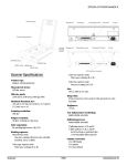
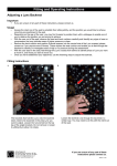
^1 USER MANUAL
^2 Accessory 12C
^3 Vacuum Fluorescent Display Unit
^4 4Ax-603601-xUxx
^5 September 24, 2003
Single Source Machine Control
Power // Flexibility // Ease of Use
21314 Lassen Street Chatsworth, CA 91311 // Tel. (818) 998-2095 Fax. (818) 998-7807 // www.deltatau.com
Copyright Information
© 2003 Delta Tau Data Systems, Inc. All rights reserved.
This document is furnished for the customers of Delta Tau Data Systems, Inc. Other uses are
unauthorized without written permission of Delta Tau Data Systems, Inc. Information contained
in this manual may be updated from time-to-time due to product improvements, etc., and may not
conform in every respect to former issues.
To report errors or inconsistencies, call or email:
Delta Tau Data Systems, Inc. Technical Support
Phone: (818) 717-5656
Fax: (818) 998-7807
Email: [email protected]
Website: http://www.deltatau.com
Operating Conditions
All Delta Tau Data Systems, Inc. motion controller products, accessories, and amplifiers contain
static sensitive components that can be damaged by incorrect handling. When installing or
handling Delta Tau Data Systems, Inc. products, avoid contact with highly insulated materials.
Only qualified personnel should be allowed to handle this equipment.
In the case of industrial applications, we expect our products to be protected from hazardous or
conductive materials and/or environments that could cause harm to the controller by damaging
components or causing electrical shorts. When our products are used in an industrial
environment, install them into an industrial electrical cabinet or industrial PC to protect them
from excessive or corrosive moisture, abnormal ambient temperatures, and conductive materials.
If Delta Tau Data Systems, Inc. products are directly exposed to hazardous or conductive
materials and/or environments, we cannot guarantee their operation.
ACC-12C
Table of Contents
INTRODUCTION .......................................................................................................................................................1
SETUP PROCEDURE ................................................................................................................................................3
DISPLAY COMMANDS ............................................................................................................................................5
CONNECTORS ...........................................................................................................................................................7
J1(JDISP) ..................................................................................................................................................................7
P1 ..............................................................................................................................................................................7
TB1............................................................................................................................................................................7
CONNECTOR PINOUTS...........................................................................................................................................9
Headers and Terminal Block Connectors..................................................................................................................9
J1 (JDISP 14-Pin Header)....................................................................................................................................9
TB1 (2-Pin Terminal Block) .................................................................................................................................9
POWER SUPPLY REQUIREMENTS....................................................................................................................11
DIAGRAMS AND SCHEMATICS..........................................................................................................................13
Table of Contents
i
ACC-12C
ii
Table of Contents
ACC-12C
INTRODUCTION
PMAC's Accessory 12C (ACC-12C) is a 2x40 character Vacuum Fluorescent Display unit which
interfaces to all versions of PMAC via their 14-pin Display Connector J1 (JDISP). This accessory is
assembled from two separate boards: the Vacuum Fluorescent board (manufactured by IEE Inc.) and the
bottom adapter board (manufactured by Delta Tau Inc.). The package includes a 6' long 14-pin flat cable
for connection to PMAC's J1 connector and a bezel with a mounted glass filter.
Refer to the enclosed schematic diagrams for dimensions and panel mounting information.
Introduction
1
ACC-12C
2
Introduction
ACC-12C
SETUP PROCEDURE
To use ACC-12C in conjunction with PMAC simply connect its J1 connector to PMAC's J1 connector via
the provided flat cable. In addition, the following PMAC memory write statements should be executed:
1. WY:$7D0,$16
2. WX:$FFFE,$xxx4
;
;
;
;
tells PMAC that the display unit is ACC-12C as
opposed to ACC-12 or ACC-12A
for extra display wait states for the standard
20MHz PMAC
or
WX:$FFFE,$xxx7
; for extra display wait states for the 30 MHz PMAC
; (PMAC+Option 5)
However, the three most significant hexadecimal digits ($xxx.) must not be changed. These digits are
set by PMAC’s firmware at the power on initialization stage based on the positions of the memory wait
state hardware jumpers. Therefore prior to the execution of step 2 above, a RHX:$FFFE,1 command
should be executed to check the value of the three most significant hexadecimal digits for a particular
PMAC.
Example: If a RHX:$FFFE,1 returns $1113 (one wait state for memory), then the step 2 above should
be WX:$FFFE,$1114 for the standard 20 MHz version of PMAC , or WX:$FFFE,$1117 for the 30
MHz version of PMAC.
Note
The memory write command in the step 2 above must be executed once per power
cycle initialization or a PMAC reset. To do this, a PLC program may be used
which disables itself after the memory write command execution.
Example: With I5=2 or 3, the following PLC program may be used:
OPEN PLC 1
CLEAR
CMD "WX:$FFFE,$xxx4"
DISABLE PLC 1
CLOSE
Setup Procedure
3
ACC-12C
4
Setup Procedure
ACC-12C
DISPLAY COMMANDS
Refer to the PMAC User's Manual for the details of available Display commands. Currently, these
commands may be issued either from within Motion programs or PLC programs. Example: To display a
message starting at the tenth character on the screen, the following command is used:
DISPLAY 10"This is a Message"
To display a PMAC variable (e.g. P100) starting at the character location 20 and with 8 digital total 3
after the decimal point, the following command may be used:
DISPLAY 20,8.3,P100
Note
PMAC's display buffer is 80 character wide with location 0 being the upper left, 39
the upper right, 40 the lower left and 79 the lower right.
Display Commands
5
ACC-12C
6
Display Commands
ACC-12C
CONNECTORS
Refer to the enclosed schematic drawing of the adapter board.
J1(JDISP)
This is a 14-pin Header which is pin-to-pin compatible with the PMAC's J1 connector and should be
connected to PMAC's J1 via the supplied flat cable.
P1
This is a 14-pin connector used for the piggyback connection of the adapter board to the main display
board.
TB1
This 2-pin terminal block allows an alternative method of power supply connection to the display unit.
Note that E1 should be removed if power is supplied via this connector. Moreover, if the connecting
cable between the PMAC and the ACC-12A is longer than 6’, use of this connector for the direct supply
of power is strongly recommended.
Connectors
7
ACC-12C
8
Connectors
ACC-12C
CONNECTOR PINOUTS
Headers and Terminal Block Connectors
J1 (JDISP 14-Pin
Header)
Pin #
Symbol
Function
1
2
3
4
5
6
7
8
9
10
11
12
13
14
Vdd
Vss
RS
Vee
E
R/W
DB1
DB0
DB3
DB2
DB5
DB4
DB7
DB6
Input
Common
Input
Input
Input
Input
Bidirectional
Bidirectional
Bidirectional
Bidirectional
Bidirectional
Bidirectional
Bidirectional
Bidirectional
Top View
Description
Notes
+5V Power
PMAC Common
Read Strobe
Contrast Adjust Vee
Display Enable
Read or Write
Display Data 1
Display Data 0
Display Data 3
Display Data 2
Display Data 5
Display Data 4
Display Data 7
Display Data 6
E1 must be installed
TTL sig. Input
0 to +5V dc
High is Enable
TTL signal Out
TTL level
TTL level
TTL level
TTL level
TTL level
TTL level
TTL level
TTL level
This is a 14-pin Header that is pin-to-pin compatible with the PMAC's J1 connector
and should be connected to PMAC's J1 via the supplied flat cable.
TB1 (2-Pin Terminal Block)
Top View
Pin #
Symbol
Function
Description
Notes
GND
Common Digital Ground
1
+5V
Input
+5V Supply
Alternative Power Supply*
2
This 2-pin terminal block allows an alternative method of power supply
connection to the display unit.
*In applications where the connecting cable between PMAC and ACC-12C is
longer than 6', bring in power through pin 2 of TB1. Connect Pin 1 of TB1 to
both PMAC's and the power supply’s ground signals. Remove jumper E1.
Connector Pinouts
9
ACC-12C
EPoint*
Physical
Layout
Description
E2
Install jumper to pass power through PMAC’s J1 connector
to ACC-12C; Remove jumper if power is brought in
through TB1.
For Future Use.
E3
For Future Use.
E1
Default
Installed
Not
Installed
Not
Installed
* These jumpers are located on the bottom side of the adapter board.
10
Connector Pinouts
ACC-12C
POWER SUPPLY REQUIREMENTS
For more detailed description of the Vacuum Fluorescent Display specifications, refer to the IEE Inc.'s
Manual (S03601-96-080). The maximum current requirement is quoted to be 580mA at 5 Volts.
Power Supply Requirements
11
ACC-12C
12
Power Supply Requirements
ACC-12C
DIAGRAMS AND SCHEMATICS
J1
7.87 in. (199.9 mm)
ACC - 12C
E2
E1
E3
2
1
.25 in
(6.4 mm)
TB1
TOP VIEW
.25 in
(6.4 mm)
SIDE VIEW
BOTTOM VIEW
NEW IDEAS IN MOTION . . .
13
Diagrams and Schematics
2.00 in (50.8 mm)
1.43 in
(36.3 mm)
ACC-12C
14
Diagrams and Schematics