1
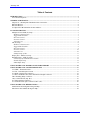
^1 USER MANUAL
^2 Accessory 5E
^3 UMAC MACRO & I/O
^4 3Ax-603437-xUxx
^5 October 23, 2003
Single Source Machine Control
Power // Flexibility // Ease of Use
21314 Lassen Street Chatsworth, CA 91311 // Tel. (818) 998-2095 Fax. (818) 998-7807 // www.deltatau.com
Copyright Information
© 2003 Delta Tau Data Systems, Inc. All rights reserved.
This document is furnished for the customers of Delta Tau Data Systems, Inc. Other uses are
unauthorized without written permission of Delta Tau Data Systems, Inc. Information contained
in this manual may be updated from time-to-time due to product improvements, etc., and may not
conform in every respect to former issues.
To report errors or inconsistencies, call or email:
Delta Tau Data Systems, Inc. Technical Support
Phone: (818) 717-5656
Fax: (818) 998-7807
Email: [email protected]
Website: http://www.deltatau.com
Operating Conditions
All Delta Tau Data Systems, Inc. motion controller products, accessories, and amplifiers contain
static sensitive components that can be damaged by incorrect handling. When installing or
handling Delta Tau Data Systems, Inc. products, avoid contact with highly insulated materials.
Only qualified personnel should be allowed to handle this equipment.
In the case of industrial applications, we expect our products to be protected from hazardous or
conductive materials and/or environments that could cause harm to the controller by damaging
components or causing electrical shorts. When our products are used in an industrial
environment, install them into an industrial electrical cabinet or industrial PC to protect them
from excessive or corrosive moisture, abnormal ambient temperatures, and conductive materials.
If Delta Tau Data Systems, Inc. products are directly exposed to hazardous or conductive
materials and/or environments, we cannot guarantee their operation.
Accessory 5E
Table of Contents
INTRODUCTION .....................................................................................................................................................1
ACC-5E Board Options ..........................................................................................................................................1
JUMPERS AND PINOUTS......................................................................................................................................3
Jumpers 1A - 1R Backplane Thumbwheel Port Connection...................................................................................3
RP4: SIP Resistor ....................................................................................................................................................4
RP5: SIP Resistor ....................................................................................................................................................4
S1: Dipswitch UBUS MACRO IC Base Address ...................................................................................................5
I/O CONFIGURATION ...........................................................................................................................................7
Multiplexer Port JTHW (J2) Setup .........................................................................................................................7
Hardware Characteristics ..................................................................................................................................7
Suggested M-Variables.......................................................................................................................................7
Direction Control ...............................................................................................................................................7
Inversion Control................................................................................................................................................8
Alternate Uses.....................................................................................................................................................8
JIO (J4) Setup..........................................................................................................................................................8
Hardware Characteristics ..................................................................................................................................8
Suggested M-Variables.......................................................................................................................................9
Direction Control ...............................................................................................................................................9
Inversion Control..............................................................................................................................................10
Alternate Uses...................................................................................................................................................10
Example Setup of JIO .......................................................................................................................................11
Display Port - JDISP (J6) Setup............................................................................................................................11
Handwheel Port – JHW (J7) Setup .......................................................................................................................11
Channel-Specific MACRO IC I-Variables........................................................................................................12
Encoder Input Setup .........................................................................................................................................12
PFM Output Setup ............................................................................................................................................13
UMAC MACRO & I/O BOARD CONNECTOR SUMMARY ..........................................................................15
UMAC MACRO & I/O CONNECTOR PINOUTS .............................................................................................17
J2: JTHW – Thumbwheel Port.............................................................................................................................17
J4: JI/O - General Purpose I/O Port .....................................................................................................................19
J6: JDISP - Display Port Connector.....................................................................................................................21
J7: JHW - Handwheel Port, Pulse and Direction Output Connector....................................................................22
TB1: Watchdog Relay Connector .........................................................................................................................23
J10,J11: MACRO I/O (Opt. B, C).........................................................................................................................23
P1: UBUS Interface Connector .............................................................................................................................25
U17: MACRO Fiber Optic Connector (OPT A, B)...............................................................................................26
UMAC MACRO & I/O MEMORY MAPS...........................................................................................................27
Identification and Configuration Register Map.....................................................................................................27
MACRO IC Base Address & Register Map..........................................................................................................28
Table of Contents
i
Accessory 5E
ii
Table of Contents
Accessory 5E
INTRODUCTION
Delta Tau’s Universal Motion and Automation Controller (UMAC) combines the power of the PMAC
controller with an integrated packaging and connectivity strategy that gives the user revolutionary
flexibility and ease of use. The UMAC consists of a set of “3U” format Euro-cards (100 x 160 mm) that
can be assembled in a variety of different strategies.
The ACC-5E UMAC MACRO & I/O accessory (P/N 300-603437-10X) provides the interface capabilities
for the LCD Display port, handwheel port, general purpose I/O port, thumbwheel port, and MACRO in
both fiber and wire formats.
ACC-5E Board Options
ACC-5E: UMAC I/O and MACRO Accessory
(Shown w/OPT2 & OPTB installed)
This 3U-size rack-mounted board provides four general-purpose (non-servo) I/O ports for the UMAC:
1.
2.
3.
4.
The JDISP display port
The JTHW multiplexor port
The JIO general-purpose I/O port
The JHW handwheel port
These are the same ports that are present along the top of a PC-bus PMAC2, or out the front of a VMEbus PMAC2. Optionally, it can also provide a 16-node or 32-node MACRO-ring interface. It connects to
the CPU board through the UBUS backplane expansion port. It is intended for Pack use only.
•
•
•
•
Option A: 16-node MACRO Interface with SC-style fiber-optic transceiver
Option B: 16-node MACRO interface with SC-style fiber-optic transceiver and RJ-45 electrical
connector
Option C: 16-node MACRO interface with RJ-45 electrical connectors
Option 2: Additional 16 nodes of MACRO interface (32 nodes total). Requires Option A, B, or C.
Introduction
1
Accessory 5E
2
Introduction
Accessory 5E
JUMPERS AND PINOUTS
The picture below shows the location of jumpers, resistor packs, dipswitch, and connectors:
P5
-H
J2
R
W
P4
TH
IN
W
M
-S
R
TE
-J
P
IS
D
-J
J6
ST
JU
AD W
H
AY
-J
PL
IS
J7
D
ES
D
R
LC
IP
N
IO
AT
R
JUMPERS
1A - 1R
LINK INDICATOR
J10 - RJ45
INPUT
J5 - JISP
J11 - RJ45
OUTPUT
U17 - FIBER
TRANSCEIVER
S1
I/O
-J
J4
DO
TB
1
H
C
H
IT
-W
AT
C
SW
IP
G
-D
MACRO & I/O Card Layout
(Shown w/OPTB installed)
Note
The ACC-5E accessory shown here is not the exact revision of the circuit board that is
currently distributed. However, all the components represented here exist on current
revisions.
Jumpers 1A - 1R Backplane Thumbwheel Port Connection
Install these 16 shorting bars when the backplane is used for thumbwheel port functions.
The UBUS Specification does not require these lines to be connected and these backplane lines may
actually be used for other purposes.
Normally these jumpers are not installed.
Jumpers and Pinouts
3
Accessory 5E
RP4: SIP Resistor
This common bussed 6-pin resistor pack is used to select between single-ended and differential
handwheel encoder inputs.
When placed with pin 1 of the resistor pack at pin 1 of the SIP socket, this resistor pack biases the
negative side of the differential handwheel encoder inputs to 2.5Vdc. This is the configuration for singleended encoders.
When placed with pin 1 of the resistor pack at pin 6 of the SIP socket, this resistor pack biases the
negative side of the differential handwheel encoder inputs to 5Vdc. This is the configuration for
differential encoders.
Refer to the schematic below for the handwheel encoder input circuit:
10
1KSIP10C
2.2KSIP6C
2
3
4
5
6
7
8
9
6
5
4
3
2
2
3
4
5
6
7
8
9
SIP SOCKET
TO CONNECTOR J7
1
RP3
2.2KSIP10C
SIP SOCKET
RP4
1
RP2
10
1
+5V
1
3
5
7
RP5
2
4
6
8
HW1_A1+
HW1_B1+
HW2_A2+
HW2_B2+
220SIP8I
GND
HW2_B2HW2_A2HW1_B1HW1_A1-
RP5: SIP Resistor
This 8-pin resistor pack has 4 individual resistors that are used to apply a termination resistance between
differential handwheel encoder inputs.
Remove this resistor pack when using single-ended encoders to reduce a threshold shift that occurs when
there is no negative side input.
Refer to the schematic above for the application of RP5 in the handwheel encoder circuit.
4
Jumpers and Pinouts
Accessory 5E
S1: Dipswitch UBUS MACRO IC Base Address
This 4-position dipswitch is used to select the UBUS address for the ACC-5E.
ACC-5E Mapping Table
{CS4 Mappings}
MACRO & I/O
SW1 Settings
4
on
on
on
on
on
on
on
on
off
off
off
off
off
off
off
off
3
on
on
on
on
off
off
off
off
on
on
on
on
off
off
off
off
2
on
on
off
off
on
on
off
off
on
on
off
off
on
on
off
off
1
on
off
on
off
on
off
on
off
on
off
on
off
on
off
on
off
Turbo
PMAC
MACR
O IC #
(m)
Base
Channel
Address
0
1
2
3
4
5
6
7
8
9
10
11
12
13
14
15
$78400
$79400
$7A400
$7B400
$78500
$79500
$7A500
$7B500
$78600
$79600
$7A600
$7B600
$78700
$79700
$7A700
$7B700
2nd Gate
Array
Base
Address
(OPT2)
$79400
$7A400
$7B400
$78500
$79500
$7A500
$7B500
$78600
$79600
$7A600
$7B600
$78700
$79700
$7A700
$7B700
Not
Availabl
e
Config.
Ident.
Address
$78F10
$79F10
$7AF10
$7BF10
$78F14
$79F14
$7AF14
$7BF14
$78F18
$79F18
$7AF18
$7BF18
$78F1C
$79F1C
$7AF1C
$7BF1C
The memory mapping for the UBUS MACRO & I/O accessory allows 16 channels to be selected. The
dipswitch selects between any of the 16 banks of memory. This allows for up to 16 ACC-5Es to be
logically configured.
Note
The ACC-5E defines the mapping for its memory depending upon whether it is a single
gate array or dual gate array device. The dual gate option for the ACC-5E is OPT-2.
The 2nd gate array base addresses are shown in the last column of the table.
Therefore, although there are 16 "slots" to place the ACC-5E into, these same "slots" may
be occupied by MACRO accessory cards that have OPT2 installed. When this occurs,
the accessory card occupies the equivalent of two slots and, therefore there may be fewer
slots available for addressing. Be careful to allow for OPT2 addressing when more than
one ACC-5E card is used!
Note
The ACC-5E with OPT-2 installed occupies 2 slots of address space. However, there is
only one CS16-identification register for the accessory card even when OPT-2 is
installed.
Jumpers and Pinouts
5
Accessory 5E
6
Jumpers and Pinouts
Accessory 5E
I/O CONFIGURATION
Two ports on the Accessory 5E may be used for general purpose I/O, the JIO (J4) port and the JTHW (J2)
port. Although their setup is similar to setting them up for a PMAC2 PC, there are some addressing
differences which need to be made clear.
Multiplexer Port JTHW (J2) Setup
The JTHW multiplexer port has 16 discrete digital I/O lines for general-purpose use. The lines are
configurable by byte for input or output (on the DSPGATE2 I/O IC, the lines are individually
configurable for input or output, but the buffer ICs are only byte-configurable), and individually
configurable for inverting or non-inverting format.
Hardware Characteristics
When configured as an output, each line has a 5V CMOS totem-pole driver. This driver can sink or
source up to 20 mA. There is a 10 κ pull-up resistor to 5V on each line for input purposes, but the driver
IC can hold the line high or low despite this resistor. When configured as an input, the buffer IC presents
a high-impedance input either sinking or sourcing; no significant current will flow. The pull-up resistor
on the line will bias the line high in the absence of anything actively pulling the line low at significantly
lower impedance.
Suggested M-Variables
The 16 I/O lines are memory-mapped into PMAC’s address space in register Y:$C082. Typically, these
lines are used as a unit with specially designed multiplexing I/O accessories and appropriate multiplexing
M-variables (TWB, TWD, TWR, and TWS formats), in which case PMAC2 handles the direct control of
these I/O lines automatically. However, these lines can also be accessed individually with M-variables.
Following is a suggested set of M-variable definitions to use these data lines:
M40->Y:$078402,8
M41->Y:$078402,9
M42->Y:$078402,10
M43->Y:$078402,11
M44->Y:$078402,12
M45->Y:$078402,13
M46->Y:$078402,14
M47->Y:$078402,15
M48->Y:$078402,8,8,U
M50->Y:$078402,0
M51->Y:$078402,1
M52->Y:$078402,2
M53->Y:$078402,3
M54->Y:$078402,4
M55->Y:$078402,5
M56->Y:$078402,6
M57->Y:$078402,7
M58->Y:$078402,0,8,U
;
;
;
;
;
;
;
;
;
;
;
;
;
;
;
;
;
;
SEL0 Line; J2 Pin 4
SEL1 Line; J2 Pin 6
SEL2 Line; J2 Pin 8
SEL3 Line; J2 Pin 10
SEL4 Line; J2 Pin 12
SEL5 Line; J2 Pin 14
SEL6 Line; J2 Pin 16
SEL7 Line; J2 Pin 18
SEL0-7 Lines treated as a byte
DAT0 Line; J2 Pin 3
DAT0 Line; J2 Pin 5
DAT0 Line; J2 Pin 7
DAT0 Line; J2 Pin 9
DAT0 Line; J2 Pin 11
DAT0 Line; J2 Pin 13
DAT0 Line; J2 Pin 15
DAT0 Line; J2 Pin 17
DAT0-7 Lines treated as a byte
Direction Control
In the default configuration set automatically at power-up/reset, DAT0 to DAT7 are set up as noninverting inputs; SEL0 to SEL7 are set up as non-inverting outputs with a zero (low voltage) value. If
any of the multiplexer port accessories are to be used, this configuration must not be changed.
The direction control bit for each of these I/O bits is located in the corresponding bit in the matching X
register. For example, the direction control bit for DAT3 is located at X:$78402,3; the direction control
bit for SEL6 is located at X:$78402,14.
I/O Configuration
7
Accessory 5E
Because the buffer ICs can only be switched by byte, it is best to define 8-bit M-variables for the
direction control. Suggested definitions are:
M60->X:$078402,0,8
M62->X:$078400,8,8
; Direction control for DAT0 to DAT7
; Direction control for SEL0 to SEL7
These M-variables should take values of 0 or 255 ($FF) only; 0 sets the byte to input, 255 sets the byte to
output.
In addition, the bi-directional buffer IC for each byte has a direction control line accessible as a software
control bit. These control lines and bits must match the ASIC direction bits. In the UMAC version of the
Turbo PMAC2, the buffer direction control bits are at UMAC address Y:$78F10,11 and Y:$78411,8.
These address are based off the Configuration Identification Address chosen by the dip switch S1 setting.
A bit value of 0 specifies input; 1 specifies output.
Suggested M-variable definitions are:
M61->Y:$78F10,11
M63->Y:$78F11,8
; Buffer direction control for DAT0 to DAT7
; Buffer direction control for SEL0 to SEL7
If it is desired to change either of these I/O bytes, it must be done by user programs (usually this is done
in PLC 1 acting as a reset PLC, scanning through once on power-up/reset, then disabling itself).
Inversion Control
Each line on the JTHW port is individually controllable as to whether it is an inverting I/O point (0=+5V;
1=0V) or a non-inverting I/O point (0=0V; 1=+5V).
Register X:$78406 contains the inversion control bits:
X:$78406 bits 0 to 7 control DAT0 to DAT7, respectively
X:$78406 bits 8 to 15 control SEL0 to SEL7, respectively
A value of 0 in the control bit sets the corresponding I/O point as non-inverting. A value of 1 in the
control bits sets the corresponding I/O point as inverting. At power-up/reset, PMAC automatically sets all
of the I/O points on the JTHW port as non-inverting. To use any of the multiplexed I/O accessory boards
on the JTHW port, all I/O points on the port must be left non-inverting.
Alternate Uses
Because of the byte-wide direction-control buffer ICs, it is not possible to use all of the I/O points on the
JTHW in their alternate uses.
Each general-purpose I/O point on the JTHW port has an alternate use as a supplemental fixed-use I/O
point on a supplemental machine interface channel (1* or 2*). The points are individually controllable as
to general-purpose use or fixed use by control register Y:$78406. Refer to this register in the memory-I/O
map to see the alternate uses of each point. At power-up/reset, UMAC automatically sets up all of the I/O
points on the port for general-purpose use.
JIO (J4) Setup
The JIO port has 32 discrete digital I/O lines for general-purpose use. The lines are configurable by byte
for input or output (on the DSPGATE2 I/O IC, the lines are individually configurable for input or output,
but the buffer ICs are only byte-configurable), and individually configurable for inverting or noninverting format.
Hardware Characteristics
Because all of these lines default to inputs at power-up/ reset, any lines used as outputs will pull to +5V at
power-up/reset until software configures them as outputs.
8
I/O Configuration
Accessory 5E
When configured as an output, each line has a 5V CMOS totem-pole driver. This driver can sink or
source up to 20 mA. There is a 10 κ pull-up resistor to 5V on each line for input purposes, but the driver
IC can hold the line high or low despite this resistor. When configured as an input, the buffer IC presents
a high-impedance sinking input; no significant current will flow. The pull-up resistor on the line will bias
the line high in the absence of anything actively pulling the line low at significantly lower impedance.
Suggested M-Variables
The 32 I/O lines are memory-mapped into UMAC’s address space in the registers Base Address and Base
Address+1, depending on SW2 settings. Typically these I/O lines are accessed individually with Mvariables. Following is a suggested set of M-variable definitions to use these data lines with a base
address of $78400:
M0->Y:$78400,0 ; I/O00 Data Line; J3 Pin 1
M1->Y:$78400,1 ; I/O01 Data Line; J3 Pin 2
M2->Y:$78400,2 ; I/O02 Data Line; J3 Pin 3
M3->Y:$78400,3 ; I/O03 Data Line; J3 Pin 4
M4->Y:$78400,4 ; I/O04 Data Line; J3 Pin 5
M5->Y:$78400,5 ; I/O05 Data Line; J3 Pin 6
M6->Y:$78400,6 ; I/O06 Data Line; J3 Pin 7
M7->Y:$78400,7 ; I/O07 Data Line; J3 Pin 8
M8->Y:$78400,8 ; I/O08 Data Line; J3 Pin 9
M9->Y:$78400,9 ; I/O09 Data Line; J3 Pin 10
M10->Y:$78400,10 ; I/O10 Data Line; J3 Pin 11
M11->Y:$78400,11 ; I/O11 Data Line; J3 Pin 12
M12->Y:$78400,12 ; I/O12 Data Line; J3 Pin 13
M13->Y:$78400,13 ; I/O13 Data Line; J3 Pin 14
M14->Y:$78400,14 ; I/O14 Data Line; J3 Pin 15
M15->Y:$78400,15 ; I/O15 Data Line; J3 Pin 16
M16->Y:$78400,16 ; I/O16 Data Line; J3 Pin 17
M17->Y:$78400,17 ; I/O17 Data Line; J3 Pin 18
M18->Y:$78400,18 ; I/O18 Data Line; J3 Pin 19
M19->Y:$78400,19 ; I/O19 Data Line; J3 Pin 20
M20->Y:$78400,20 ; I/O20 Data Line; J3 Pin 21
M21->Y:$78400,21 ; I/O21 Data Line; J3 Pin 22
M22->Y:$78400,22 ; I/O22 Data Line; J3 Pin 23
M23->Y:$78400,23 ; I/O23 Data Line; J3 Pin 24
M24->Y:$78401,0 ; I/O24 Data Line; J3 Pin 25
M25->Y:$78401,1 ; I/O25 Data Line; J3 Pin 26
M26->Y:$78401,2 ; I/O26 Data Line; J3 Pin 27
M27->Y:$78401,3 ; I/O27 Data Line; J3 Pin 28
M28->Y:$78401,4 ; I/O28 Data Line; J3 Pin 29
M29->Y:$78401,5 ; I/O29 Data Line; J3 Pin 30
M30->Y:$78401,6 ; I/O30 Data Line; J3 Pin 31
M31->Y:$78401,7 ; I/O31 Data Line; J3 Pin 32
Direction Control
The direction control bit for each of these I/O bits is located in the corresponding bit in the matching X
register. For example, with the base address set at $78400 the direction control bit for I/O03 is located at
X:$78400,3; the direction control bit for I/O30 is located at X:$78401,6. Because the buffer ICs can only
be switched by byte, it is best to define 8-bit M-variables for the direction control. Suggested definitions
are:
M32->X:$78400,0,8 ; Direction control for I/O00 to I/O07
M34->X:$78400,8,8 ; Direction control for I/O08 to I/O15
M36->X:$78400,16,8 ; Direction control for I/O16 to I/O23
M38->X:$78401,0,8 ; Direction control for I/O24 to I/O31
I/O Configuration
9
Accessory 5E
These M-variables should take values of 0 or 255 ($FF) only; 0 sets the byte to input, 255 sets the byte to
output. The default values are zero for all of the above registers.
In addition, the bidirectional buffer IC for each byte has a direction control line accessible as a software
control bit. These control lines and bits must match the ASIC direction bits. The buffer direction control
bits are at the UMAC Configuration Identification Address (depends on SW2), with bits 7 to 10
controlling the four bytes of the JIO port. A bit value of 0 specifies input; 1 specifies output. With base
address of $78400, the suggested M-variable definitions are:
M33->Y:$78F10,7 ; Buffer direction control for I/O00 to I/O07
M35->Y:$78F10,8 ; Buffer direction control for I/O08 to I/O15
M37->Y:$78F10,9 ; Buffer direction control for I/O16 to I/O23
M39->Y:$78F10,10 ; Buffer direction control for I/O24 to I/O31
In the default configuration automatically set at power-up/reset, I/O00 to I/O31 are set up as inputs (M32
through M39 = 0). This is done for maximum safety; no lines can be forced into an undesirable high or
low state. Any of these lines that are to be used as outputs must be changed to outputs by user programs
(usually this is done in PLC 1 acting as a reset PLC, scanning through once on power-up/reset, then
disabling itself).
Inversion Control
Each line on the JIO port is individually controllable as to whether it is an inverting I/O point (0=+5V;
1=0V) or a non-inverting I/O point (0=0V; 1=+5V). For base address $78400, registers X:$78404 and
X:$78405 contain the inversion control bits:
X:$78404 bits 0 to 23 control I/O00 to I/O23, respectively
X:$78405 bits 0 to 7 control I/O24 to I/O31, respectively
Suggested M-Variable definitions
m41->x:$78404,0,8
m42->x:$78404,8,8
m43->x:$78404,16,8
m44->x:$78405,0,8
m45->x:$78404,0,24
A value of 0 in the control bit sets the corresponding I/O point as inverting. A value of 1 in the control
bits sets the corresponding I/O point as non-inverting. At power-up/reset, UMAC automatically sets all of
the I/O points on the JIO port as inverting. On power up all of the inputs are at zero and pulled up to 5V.
Alternate Uses
The direction-control of the buffer ICs must be set properly for the alternate uses of the I/O points, just as
for the general-purpose I/O uses. These lines must be set properly at power up.
Each general-purpose I/O point on the JIO port has an alternate use as a supplemental fixed-use I/O point
on a supplemental machine interface channel (1* or 2*). The default setting of configures this port for the
general purpose I/O. If the user needs the supplemental channel registers, then you must set these bits to
0 at power up to use each line as a general-purpose I/O point. The points are individually controllable as
to general-purpose use or fixed use by control registers Y:$78404 and Y:$78405, when base address is at
$78400. Refer to these registers in the memory-I/O map to see the alternate uses of each point. At powerup/ reset, UMAC automatically sets up all of the I/O points on the port for general-purpose use
Suggested M-Variable Definitions
M46->Y:$78404,0,24
M47->Y:$78405,0,8
10
;setup for IO0-23
;setup for IO24-32
I/O Configuration
Accessory 5E
Example Setup of JIO
If the above definitions were made, we could set these variables to their proper values in an initialization
PLC. This example sets up the first 2 bytes as outputs and the second 2 bytes as inputs. All set to noninverting. I usually will use the following technique for an initialization PLC,
#define
#define
#define
#define
#define
#define
#define
#define
#define
#define
#define
#define
DIR_CONTROL_1
BUFF_CONTROL_1
DIR_CONTROL_2
BUFF_CONTROL_2
DIR_CONTROL_3
BUFF_CONTROL_3
DIR_CONTROL_4
BUFF_CONTROL_4
INV_CTRL_0_23
INV_CTRL_24_31
Alt_use_0_23
Alt_use_24_31
m32
m33
m34
m35
m36
m37
m38
m39
m45
m44
m46
m47
OPEN PLC 6 CLEAR
DIR_CONTROL_1 = 255 ;set as output
BUF_CONTROL_1 = 1 ;set as output
DIR_CONTROL_2 = 255 ;set as output
BUF_CONTROL_2 = 1 ;set as output
DIR_CONTROL_3 = 0 ;set as input
BUF_CONTROL_3 = 0 ;set as input
DIR_CONTROL_4 = 0 ;set as input
BUF_CONTROL_4 = 0 ;set as input
INV_CTRL_0_23 = $FFFF ;set as non-inverting
INV_CTRL_24_31 =$FF ;set as non-inverting
Alt_use_0_23 = $FFFFFF
Alt_use_0_7 = $FF
;place other initialization variables here
while (1<2)
;PLC in here (perhaps E_STOP routine)
.
.
endwhile
CLOSE
Display Port - JDISP (J6) Setup
The JDISP connector (J6) allows connection of the ACC-12 or ACC-12A liquid crystal displays, or of the
Acc-12C vacuum fluorescent display. Both text and variable values may be shown on these displays
using the DISPLAY command, executing in either motion or PLC programs.
Handwheel Port – JHW (J7) Setup
The Handwheel port on the Acc5E is a convenient and cheap tool to use for an extra two encoder inputs
and two PFM outputs. The encoder input lines do not provide a method for inputting an index pulse, but
quadrature encoder input is available. The 2 PFM outputs can used be used in many different
applications including driving stepper motors or laser outputs.
I/O Configuration
11
Accessory 5E
Channel-Specific MACRO IC I-Variables
(For MACRO IC Channel n*, where n* = 1 to 2) I-Variables in the I6810s, I6820s, I6910s, and I6920s
control the hardware aspects of the MACRO IC “DSPGATE2” ASIC that provides the machine interface
for supplemental channels 1 and 2. Note that few of these functions are normally used on the Turbo
PMAC2s. By default, only the two encoder inputs and the two C-channel PWM/PFM outputs are used.
These I-variables are not active if the MACRO IC is not present, or is a “MACROGATE” IC.
Encoder Input Setup
To set up a supplemental encoder channel through the thumbwheel port, there is very little software setup
involved. One parameter you will have to change is the encoder decode. This UMAC I variable is I68n0
or I69n0, where is the supplemental channel. There is firmware support for a system with 4 Acc5E’s
addressed to Macro IC #0-3 (based on the settings of S1). You could then access to 8 supplemental
encoder channels with I-variable pointers. Since it is possible to connect up to 16 Accessory 5Es into a
system, there are methods available to set up additional supplemental encoders through M-Variable
pointers. Consult Delta Tau Technical Support if you wish to bring in more than 8 supplemental encoder
channels.
I68n0/I69n0
I68n0 and I69n0 control how the encoder input signal for Channel n* (n* = 1 to 2) on a “DSPGATE2”
MACRO IC is decoded into counts. For MACRO ICs 0 and 2, n = n*; for MACRO ICs 1 and 3, n = n* +
5 (i.e. I6810 controls MACRO IC 0 Channel 1; I6970 controls MACRO IC 3 Channel 2). As such, this
defines the sign and magnitude of a “count”. The following settings may be used to decode an input
signal.
I68n0/I69n0 = 0: Pulse and direction CW
I68n0/I69n0 = 1: x1 quadrature decode CW
I68n0/I69n0 = 2: x2 quadrature decode CW
I68n0/I69n0 = 3: x4 quadrature decode CW
I68n0/I69n0 = 4: Pulse and direction CCW
I68n0/I69n0 = 5: x1 quadrature decode CCW
I68n0/I69n0 = 6: x2 quadrature decode CCW
I68n0/I69n0 = 7: x4 quadrature decode CCW
I68n0/I69n0 = 8: Internal pulse and direction
I68n0/I69n0 = 9: Not used
I68n0/I69n0 = 10: Not used
I68n0/I69n0 = 11: x6 hall format decode CW*
I68n0/I69n0 = 12: MLDT pulse timer control (Internal pulse resets timer; external pulse latches timer)
I68n0/I69n0 = 13: Not used
I68n0/I69n0 = 14: Not used
I68n0/I69n0 = 15: x6 hall format decode CCW*
*Requires version B or newer of the DSPGATE2 MACRO IC.
12
I/O Configuration
Accessory 5E
After setting up the decode properties you can process the data in the encoder conversion table. The
encoder counter data for the first encoder will be located at the BaseAddress+11 from your SW1 setting.
The second channel of encoder data will be at BaseAddress+19. The following is an example for the
encoder conversion table settings for an Accessory 5E with two encoders wired into the Handwheel port
and switch settings for a base address of $78400.
I6810=7
I6820=7
I8008=$78410
I8009=$78418
I903=$3509
I904=$3509
I1003=$350a
I1004=$350a
;x4 quadrature decode CCW
;x4 quadrature decode CCW
;1/T interpolation where data is at $78411 at 9th
;entry of ECT
;1/T interpolation where data is at $78419 at
;10th entry of ECT
;Motor 9 position is now set up for position
;feedback through the handwheel port
;Motor 9 position is now set up for velocity
feedback through the handwheel port
;Motor 10 position is now set up for position
feedback through the handwheel port
;Motor 10 position is now set up for velocity
feedback through the handwheel port
Alternatively, you could use the data from the following M-Variables:
M901->X:$78411,0,24
M991->X:$3509,0,24
M1001->X:$78419,0,24
M1091->X:$350a,0,24
;encoder counter for handwheel encoder 1
;output from the encoder conversion table with
;1/T interpolation
;encoder counter for handwheel encoder 1
;output from the encoder conversion table with
;1/T interpolation
I68n2/I69n2 and I68n3/I69n3 are used to setup the encoder capture characteristics (see Turbo Software
Reference Manual). If you are using the encoder capture function, the captured data will be located at
X:$BaseAddress+3,0,24.
PFM Output Setup
There is also very little setup needed when configuring the 2 PFM output signals on the Handwheel port
of the 5E. Variables I68n6/I69n6 through I68n8/I69n8 are the variables provided through firmware. You
can reference all of these variables in the Turbo Software Reference Manual.
I68n6/I69n6
I68n6/I69n6 = 0: Outputs A & B are PWM; Output C is PWM
I68n6/I69n6 = 1: Outputs A & B are DAC; Output C is PWM
I68n6/I69n6 = 2: Outputs A & B are PWM; Output C is PFM
I68n6/I69n6 = 3: Outputs A & B are DAC; Output C is PFM
Since we want PFM outputs we would select a value of 2 or 3 for this variable. The output register will
then be located at address $BaseAddress+4,8,16,s for the first PFM output and $BaseAddress+12,8,16,s
for the second PFM channel.
Example for Base Address of $78400:
I6816=3
I6826=3
M902->X:$78414,8,16,S
M1002->X:$7841C,8,16,S
I/O Configuration
;first supplemental channel output mode
;second supplemental channel output mode
;first supplemental output channel PFM address
;Second supplemental output channel PFM address
13
Accessory 5E
Now by setting M902 or M1002 to a value, you will see the PFM output on pins 11-18 on the handwheel
port. The maximum value of M902 or M1002 is 32767 will corresponds to a PFM value ½ the PFM
clock set by I6803. The pulse width is configured through I6804 for all of the channels at the same base
address. Reference the Turbo Software Reference Manual for all of the details of this setup.
14
I/O Configuration
Accessory 5E
UMAC MACRO & I/O BOARD CONNECTOR SUMMARY
J2:
JTHW
-
Thumbwheel port connector: 26-pin box header connector
J3:
JIO
-
I/O interface connector (32 I/O lines): 40-pin box header connector
J5:
JTAG
-
Programming header (Factory use only)
J6:
JDISP
-
Alphanumeric display connector: 14-pin box header
J7:
JHW
-
Handwheel port, pulse and direction output combined: 20-pin box header
J9:
WD
-
Watchdog relay connector: 4-pin mini-combicon connector
J10:
RJ45IN
-
MACRO wire-based input: 8-pin RJ45 connector (OPTB or OPTC only)
J11:
RJ45OUT
-
MACRO wire-based output: 8-pin RJ45 connector (OPTB or OPTC only)
P1:
JEXP
-
UBUS Interface (96-pin DIN connector)
U17:
OPTOXCVR
-
MACRO Fiber optic interface: 2- SC style optical connectors (OPTA or OPTB
only)
UMAC MACRO & I/O Board Connector Summary
15
Accessory 5E
16
UMAC MACRO & I/O Board Connector Summary
Accessory 5E
UMAC MACRO & I/O CONNECTOR PINOUTS
The schematic circuits shown in this section are for interface reference only. Subtle differences may exist
between the circuits shown here and the actual hardware used.
J2: JTHW – Thumbwheel Port
(26-pin Header)
Pin #
Symbol
Function
Description
Front View
Notes
1
GND
Common
Power Supply Return
2
GND
Common
Power Supply Return
3
DAT0
Bidirect
Thumbwheel Data Line 0
4
SEL0
Bidirect
Thumbwheel Select Line 0
5
DAT1
Bidirect
Thumbwheel Data Line 1
6
SEL1
Bidirect
Thumbwheel Select Line 1
7
DAT2
Bidirect
Thumbwheel Data Line 2
8
SEL2
Bidirect
Thumbwheel Select Line 2
9
DAT3
Bidirect
Thumbwheel Data Line 3
10
SEL3
Bidirect
Thumbwheel Select Line 3
11
DAT4
Bidirect
Thumbwheel Data Line 4
12
SEL4
Bidirect
Thumbwheel Select Line 4
13
DAT5
Bidirect
Thumbwheel Data Line 5
14
SEL5
Bidirect
Thumbwheel Select Line 5
15
DAT6
Bidirect
Thumbwheel Data Line 6
16
SEL6
Bidirect
Thumbwheel Select Line 6
17
DAT7
Bidirect
Thumbwheel Data Line 7
18
SEL7
Bidirect
Thumbwheel Select Line 7
19
n.c.
Not Connected
20
GND
Common
Power Supply Return
21
n.c.
Not Connected
22
GND
Common
Power Supply Return
23
n.c.
Not Connected
24
GND
Common
Power Supply Return
25
+5V
Vcc
Power Supply
Pwr supply output from UBUS backplane
26
n.c.
Not Connected
The JTHW connector provides the UMAC system with the ability to communicate either by using the thumbwheel port
protocol or by a user-created parallel means.
UMAC MACRO & I/O Connector Pinouts
17
Accessory 5E
+5V
+5V
U9
48
47
46
45
44
43
42
41
40
39
38
37
36
35
34
33
32
31
30
29
28
27
26
25
DATA_0
DATA_1
DATA_2
DATA_3
DATA_4
DATA_5
DATA_6
DATA_7
C23
OE1
A0
A1
GND
A2
A3
VCC
A4
A5
GND
A6
A7
A8
A9
GND
A10
A11
VCC
A12
A13
GND
A14
A15
OE2
T/R1
B0
B1
GND
B2
B3
VCC
B4
B5
GND
B6
B7
B8
B9
GND
B10
B11
VCC
B12
B13
GND
B14
B15
T/R2
74FCT16245ATA
(TSSOP)
.1UF
1
2
3
4
5
6
7
8
9
10
11
12
13
14
15
16
17
18
19
20
21
22
23
24
J2
J2
OUT4
C24
.1UF
GND
GND
+5V
+5V
U10
SEL_6
SEL_7
C25
.1UF
GND
74FCT16245ATA
(TSSOP)
9
8
7
6
5
4
3
2
RP10
RP11
1
+5V
10KSIP10C
10
SEL_4
SEL_5
OUT5
1
2
3
4
5
6
7
8
9
10
11
12
13
14
15
16
17
18
19
20
21
22
23
24
1
SEL_2
SEL_3
T/R1
B0
B1
GND
B2
B3
VCC
B4
B5
GND
B6
B7
B8
B9
GND
B10
B11
VCC
B12
B13
GND
B14
B15
T/R2
9
8
7
6
5
4
3
2
SEL_0
SEL_1
OE1
A0
A1
GND
A2
A3
VCC
A4
A5
GND
A6
A7
A8
A9
GND
A10
A11
VCC
A12
A13
GND
A14
A15
OE2
10
48
47
46
45
44
43
42
41
40
39
38
37
36
35
34
33
32
31
30
29
28
27
26
25
1
2
3
4
5
6
7
8
9
10
11
12
13
14
15
16
17
18
19
20
21
22
23
24
25
26
DAT0
SEL0
DAT1
SEL1
DAT2
SEL2
DAT3
SEL3
DAT4
SEL4
DAT5
SEL5
DAT6
SEL6
DAT7
SEL7
10KSIP10C
(JTHW)
GND
GND
DAT0
SEL0
DAT1
SEL1
DAT2
SEL2
DAT3
SEL3
DAT4
SEL4
DAT5
SEL5
DAT6
SEL6
DAT7
SEL7
N.C.
GND
N.C.
GND
N.C.
GND
+5V
N.C.
HEADER 26
GND
C26
.1UF
GND
Circuitry for J2 JTHW Interface
18
UMAC MACRO & I/O Connector Pinouts
Accessory 5E
J4: JI/O - General Purpose I/O Port
(40-pin Header)
Front View
Pin #
Symbol
Function
1
2
3
4
5
6
7
8
9
10
11
12
13
14
15
16
17
18
19
20
21
22
23
24
25
26
27
28
29
30
31
32
33
34
35
36
37
38
39
40
I/O00
I/O01
I/O02
I/O03
I/O04
I/O05
I/O06
I/O07
I/O08
I/O09
I/O10
I/O11
I/O12
I/O13
I/O14
I/O15
I/O16
I/O17
I/O18
I/O19
I/O20
I/O21
I/O22
I/O23
I/O24
I/O25
I/O26
I/O27
I/O28
I/O29
I/O30
I/O31
GND
GND
PHASE
SERVO
GND
GND
+5V
Bidirect
Bidirect
Bidirect
Bidirect
Bidirect
Bidirect
Bidirect
Bidirect
Bidirect
Bidirect
Bidirect
Bidirect
Bidirect
Bidirect
Bidirect
Bidirect
Bidirect
Bidirect
Bidirect
Bidirect
Bidirect
Bidirect
Bidirect
Bidirect
Bidirect
Bidirect
Bidirect
Bidirect
Bidirect
Bidirect
Bidirect
Bidirect
Common
Common
Output
Output
Common
Common
Vcc
Vcc
+5V
UMAC MACRO & I/O Connector Pinouts
Description
Input or Output #00
Input or Output #01
Input or Output #02
Input or Output #03
Input or Output #04
Input or Output #05
Input or Output #06
Input or Output #07
Input or Output #08
Input or Output #09
Input or Output #10
Input or Output #11
Input or Output #12
Input or Output #13
Input or Output #14
Input or Output #15
Input or Output #16
Input or Output #17
Input or Output #18
Input or Output #19
Input or Output #20
Input or Output #21
Input or Output #22
Input or Output #23
Input or Output #24
Input or Output #25
Input or Output #26
Input or Output #27
Input or Output #28
Input or Output #29
Input or Output #30
Input or Output #31
Power Supply Return
Power Supply Return
Phase Clock Output
Servo Clock Output
Power Supply Return
Power Supply Return
Power Supply
Power Supply
Notes
Pwr supply output from UBUS backplane
Pwr supply output from UBUS backplane
19
Accessory 5E
+5V
+5V
U10
48
47
46
45
44
43
42
41
40
39
38
37
36
35
34
33
32
31
30
29
28
27
26
25
IO_00
IO_01
IO_02
IO_03
IO_04
IO_05
IO_06
IO_07
C25
OE1
A0
A1
GND
A2
A3
VCC
A4
A5
GND
A6
A7
A8
A9
GND
A10
A11
VCC
A12
A13
GND
A14
A15
OE2
T/R1
B0
B1
GND
B2
B3
VCC
B4
B5
GND
B6
B7
B8
B9
GND
B10
B11
VCC
B12
B13
GND
B14
B15
T/R2
1
2
3
4
5
6
7
8
9
10
11
12
13
14
15
16
17
18
19
20
21
22
23
24
OUT5
OUT0
J3
74FCT16245ATA
(TSSOP)
C26
J3
.1UF
.1UF
I/O00
I/O01
I/O02
I/O03
I/O04
I/O05
I/O06
I/O07
I/O08
I/O09
I/O10
I/O11
I/O12
I/O13
I/O14
I/O15
I/O16
I/O17
I/O18
I/O19
I/O20
I/O21
I/O22
I/O23
I/O24
I/O25
I/O26
I/O27
I/O28
I/O29
I/O30
I/O31
U11
OUT2
74FCT16245ATA
(TSSOP)
C28
.1UF
IO_28
IO_29
IO_30
IO_31
PHASE
SERVO
C29
.1UF
GND
T/R1
B0
B1
GND
B2
B3
VCC
B4
B5
GND
B6
B7
B8
B9
GND
B10
B11
VCC
B12
B13
GND
B14
B15
T/R2
74FCT16245ATA
(TSSOP)
1
2
3
4
5
6
7
8
9
10
11
12
13
14
15
16
17
18
19
20
21
22
23
24
OUT3
RP12
10
IO_26
IO_27
OE1
A0
A1
GND
A2
A3
VCC
A4
A5
GND
A6
A7
A8
A9
GND
A10
A11
VCC
A12
A13
GND
A14
A15
OE2
10KSIP10C
RP13
10KSIP10C
RP14
10KSIP10C
RP15
1
U12
48
47
46
45
44
43
42
41
40
39
38
37
36
35
34
33
32
31
30
29
28
27
26
25
1
2
3
4
5
6
7
8
9
10
11
12
13
14
15
16
17
18
19
20
21
22
23
24
25
26
27
28
29
30
31
32
33
34
35
36
37
38
39
40
9
8
7
6
5
4
3
2
.1UF
IO_24
IO_25
10
C27
1
IO_22
IO_23
9
8
7
6
5
4
3
2
IO_20
IO_21
10
IO_18
IO_19
1
IO_14
IO_15
IO_16
IO_17
9
8
7
6
5
4
3
2
IO_12
IO_13
T/R1
B0
B1
GND
B2
B3
VCC
B4
B5
GND
B6
B7
B8
B9
GND
B10
B11
VCC
B12
B13
GND
B14
B15
T/R2
10
IO_10
IO_11
OE1
A0
A1
GND
A2
A3
VCC
A4
A5
GND
A6
A7
A8
A9
GND
A10
A11
VCC
A12
A13
GND
A14
A15
OE2
OUT1
1
IO_08
IO_09
1
2
3
4
5
6
7
8
9
10
11
12
13
14
15
16
17
18
19
20
21
22
23
24
9
8
7
6
5
4
3
2
48
47
46
45
44
43
42
41
40
39
38
37
36
35
34
33
32
31
30
29
28
27
26
25
+5V
10KSIP10C
(JI/O)
I/O00
I/O01
I/O02
I/O03
I/O04
I/O05
I/O06
I/O07
I/O08
I/O09
I/O10
I/O11
I/O12
I/O13
I/O14
I/O15
I/O16
I/O17
I/O18
I/O19
I/O20
I/O21
I/O22
I/O23
I/O24
I/O25
I/O26
I/O27
I/O28
I/O29
I/O30
I/O31
GND
GND
PHASESERVOGND
GND
+5V
+5V
HEADER 40
GND
C30
.1UF
GND
Circuitry For J3 JI/O Interface
20
UMAC MACRO & I/O Connector Pinouts
Accessory 5E
J6: JDISP - Display Port Connector
(14-pin Header)
Pin #
1
2
3
4
5
6
7
8
9
10
11
12
13
14
Note 1:
Note 2:
Note 3:
Note 4:
Symbol
Function
Description
Front View
Notes
+5V
Vcc
Power Supply
Pwr supply output from UBUS backplane
GND
Common
Power Supply Return
RS
Output
Read Select
Connected to OUT8Vee
Output
LCD Display Intensity
Pot adjusts between 5V and GND
E
Output
LCD Display Enable
Connected to OUT7R/WOutput
Read/write- Signal
Connected to OUT6DB1
Bidirect
Data Bit 1
DB0
Bidirect
Data Bit 0
DB3
Bidirect
Data Bit 3
DB2
Bidirect
Data Bit 2
DB5
Bidirect
Data Bit 5
DB4
Bidirect
Data Bit 4
DB7
Bidirect
Data Bit 7
DB6
Bidirect
Data Bit 6
Upon a clear-reset power-up, this port will automatically output data to the LCD device.
This port is designed to operate with the ACC-12 display products from Delta Tau Data Systems Inc.
This port is capable of being used as an 8-bit parallel input or output.
The value of Y:$10D0 (for Turbo UMAC) is set to $80 for ACC-12A (LCD Display). Set this register to $16 for
ACC-12C (Vacuum Fluorescent Display) or basic parallel output from the display buffer register. Set this register
to 00 if the JDISP connector is to be used as an 8-bit parallel port.
UMAC MACRO & I/O Connector Pinouts
21
Accessory 5E
J7: JHW - Handwheel Port, Pulse
and Direction Output Connector
(20-pin Header)
Front View
Pin #
Symbol
Function
1
2
3
4
5
6
7
8
9
10
11
12
13
14
15
16
17
18
19
20
GND
+5V
HW1_A+
HW1_AHW1_B+
HW1_BHW2_A+
HW2_AHW2_B+
HW2_BPUL1+
PUL1DIR1+
DIR1PUL2+
PUL2DIR2+
DIR2GND
+5V
Common
Vcc
Input
Input
Input
Input
Input
Input
Input
Input
Output
Output
Output
Output
Output
Output
Output
Output
Common
Vcc
Description
Notes
Power Supply Return
Power Supply
Handwheel #1 'A+' Input
Handwheel #1 'A-' Input
Handwheel #1 'B+' Input
Handwheel #1 'B-' Input
Handwheel #2 'A+' Input
Handwheel #2 'A-' Input
Handwheel #2 'B+' Input
Handwheel #2 'B-' Input
Pulse Output #1+
Pulse Output #1Direction Output #1+
Direction Output #1Pulse Output #2+
Pulse Output #2Direction Output #2+
Direction Output #2Power Supply Return
Power Supply
Pwr supply output from UBUS backplane
Pwr supply output from UBUS backplane
10
RP2
1
10
1
+5V
RP3
SIP SOCKET
1
6
5
4
3
2
1KSIP10C
SIP SOCKET
2
3
4
5
6
7
8
9
RP4
HW1_A1HW1_B1HW2_A2HW2_B2-
2.2KSIP6C
1
3
5
7
RP5
2
3
4
5
6
7
8
9
2.2KSIP10C
2
4
6
8
HW1_A1+
HW1_B1+
HW2_A2+
HW2_B2+
220SIP8I
GND
+5V
U8
VCC
HW1_A1
3
4
OUT-A
IN-A
IN-A
EN-A,C
IN-C
HW1_B1
5
HW2_A2
13
12
OUT-C
IN-C
OUT-B
IN-B
IN-B
EN-B,D
IN-D
HW2_B2
11
OUT-D
J7
+5V
U7
IN-D
GND
16
J7
VCC
2
HW1_A1+
1
HW1_A1-
7
HW1_B1-
6
HW1_B1+
PUL_1
7
14
HW2_A2+
DIR_2
15
15
HW2_A2-
DIR_1
1
4
HW2_B2-
10
HW2_B2+
OUT-A
OUT-A
EN-A,C
OUT-C
12
9
IN-A
IN-C
IN-B
OUT-C
OUT-B
OUT-B
EN-B,D
OUT-D
PUL_2
9
IN-D
8
OUT-D
GND
ST34C86CF16
(SO16)
16
2
DIR_1+
3
DIR_1-
5
PUL_1-
6
PUL_1+
14
DIR_2+
13
DIR_2-
11
PUL_2-
10
PUL_2+
8
GND
+5V
ST34C87CF16
(SO16)
HW1_A1+
HW1_A1HW1_B1+
HW1_B1HW2_A2+
HW2_A2HW2_B2+
HW2_B2PUL_1+
PUL_1DIR_1+
DIR_1PUL_2+
PUL_2DIR_2+
DIR_2-
1
2
3
4
5
6
7
8
9
10
11
12
13
14
15
16
17
18
19
20
(JHW,PD)
GND
+5V
HW1_A1+
HW1_A1HW1_B1+
HW1_B1HW2_A2+
HW2_A2HW2_B2+
HW2_B2PUL_1+
PUL_1DIR_1+
DIR_1PUL_2+
PUL_2DIR_2+
DIR_2GND
+5V
HEADER 20
C21
.1UF
GND
GND
+5V
C22
.1UF
GND
Circuitry For J7 JHW Interface
22
UMAC MACRO & I/O Connector Pinouts
Accessory 5E
TB1: Watchdog Relay Connector
(4 pin Mini-Combicon)
Pin #
Symbol
Function
1
NC
Relay Contact
Normally closed contact
Description
2
3
COM
NO
Relay Contact
Relay Contact
Watchdog Common
Normally open contact
4
COM
Relay Contact
Watchdog Common
Front View
Notes
This Pin is connected to J9-2 and J9-4
when the watchdog is tripped.
Connected to pin 4.
This pin is connected to J9-2 and J9-4
when the system is functioning normally.
This pin is disconnected when the
Watchdog circuit trips (error condition).
Connected to pin 2.
J9-WD
+5V
K1
J9
3
4
3
5
D2
10
1
2
3
4
NC
COM
NO
COM
9
8
MMBD301LT1
(SOT23)
1
1
1
12
FBR12ND05
Q1
2N7002
3
2
SOT23
GND
Watchdog Relay Circuit
J10,J11: MACRO I/O (Opt. B, C)
(8 pin RJ45)
Pin #
Symbol
Function
Description
1
DATA+
Data +
Differential MACRO Signal.
Front View
Notes
J10: DATA+ input.
J11: DATA+ output.
2
DATAData Differential MACRO Signal
J10: DATA- input.
J11: DATA- output.
3
Unused
Unused terminated pin
See schematic below.
4
Unused
Unused terminated pin
See schematic below.
5
Unused
Unused terminated pin
See schematic below.
6
Unused
Unused terminated pin
See schematic below.
7
Unused
Unused terminated pin
See schematic below.
8
Unused
Unused terminated pin
See schematic below.
The cable used for MACRO wired connections is CAT5 verified straight-through 8 conductor.
UMAC MACRO & I/O Connector Pinouts
23
Accessory 5E
J11
rj45
J11
tx+
tx-
1
2
3
4
5
6
7
8
CON8
R23
50
R24
50
R31
50
R25
50
R26
50
R32
50
R27
50
R28
50
R33
50
J10
rj45
J10
rx+
rx-
U18
14
15
16
CT
TDTD+
CMT
TXTX+
CT
RDRD+
CT
RXRX+
12
11
10
1
2
3
4
5
6
7
8
CON8
3
2
1
5
6
7
R37
50
R38
50
R39
50
R40
50
R41
50
R42
50
PE-68515
M5
MTG HOLE
R36
75
R35
75
R43
50
R44
50
R45
50
C64
.01 mfd 2kv
24
UMAC MACRO & I/O Connector Pinouts
Accessory 5E
P1: UBUS Interface Connector
(96 pin EURO-Connector)
Pin #
Row A
Front View on Accessory Card
Row B
Row C
1
+5Vdc
+5Vdc
+5Vdc
2
GND
GND
GND
3
BD01
DAT0
BD00
4
BD03
SEL0
BD02
5
BD05
DAT1
BD04
6
BD07
SEL1
BD06
7
BD09
DAT2
BD08
8
BD11
SEL2
BD10
9
BD13
DAT3
BD12
10
BD15
SEL3
BD14
11
BD17
DAT4
BD16
12
BD19
SEL4
BD18
13
BD21
DAT5
BD20
14
BD23
SEL5
BD22
15
BS1
DAT6
BS0
16
BA01
SEL6
BA00
17
BA03
DAT7
BA02
18
BX/Y
SEL7
BA04
19
N.C.
BA06
N.C.
20
BA05
BA07
CS421
N.C.
BA08
N.C.
22
CS16BA09
N.C.
23
BA13
BA10
BA12
24
BRDBA11
BWR25
BS3
MEMCS0BS2
26
MEMCS1RESET
27
PHASE+
IREQ1SERVO+
28
PHASEIREQ2SERVO29
N.C.
IREQ3N.C.
30
-15Vdc
N.C.
+15Vdc
31
GND
GND
GND
32
+5Vdc
+5Vdc
+5Vdc
1. Refer to the UBUS Specification for detailed signal descriptions.
2. Items shown in gray boxes represent optional UBUS backplane operation. Jumpers must be installed to use these
signals.
UMAC MACRO & I/O Connector Pinouts
25
Accessory 5E
U17: MACRO Fiber Optic Connector
(OPT A, B)
(2 Socket SC-Style)
Front View
Pin #
Symbol
Function
Description
Notes
1
RX
Fiber Input
MACRO Ring Receiver
2
TX
Fiber Output
MACRO Ring Transmitter
1. The fiber optic version of MACRO uses 62.5/125 multi-mode glass fiber optic cable terminated in an SC-style
connector. The optical wavelength is 1,300nm.
2. It is possible to "adapt" wire to fiber operation when using OPT B.
26
UMAC MACRO & I/O Connector Pinouts
Accessory 5E
UMAC MACRO & I/O MEMORY MAPS
The diagrams below shows the mapping of the registers used in the ACC-5E.
There are two maps shown here: They represent the layout for the CS16- identification registers and the
CS4- Gate Array Select registers.
Identification and Configuration Register Map
Identification Register (CS16-) TABLE
15
14
13
12
10
9
8
7
6
5
4
3
2
1
VENDOR
0
BASE
11
SCLK
16
VLTN
17
W/F
18
OUT0
19
OUT1
20
OUT2
21
OUT3
22
OUT4
23
+1
BANK
DLB
BIST
OUT5
OUT6
OUT7
OUT8
+2
LINK FAULT-
BANK 0
LTCOMP
CODE
OPTION CODE
+3
OUT1
OUT0
W/F
VLTN
SCLK
OUT6
OUT5
BIST
DLB
LTCOMP
BANK
CARD
TYPE
+2
LINK FAULT-
BANK 1
OUT2
OUT7
+1
OUT3
OUT8
BASE
OUT4
REVISION
+3
UMAC MACRO & I/O Memory Maps
27
Accessory 5E
SCLK: (Read/Write)
0 = Servo and phase clock input mode (Source is supplied from UBUS)
1 = Servo and phase clock source (power-up default)
VLTN: (Violation Status) (Read Only)
0 = No violation
1 = Violation
W/F:
(Wire/Fiber) (Read/Write)
0 = Fiber (Power-up default)
1 = Wire
BANK: (Bank Select) (Read/Write)
0 = Bank 0
1 = Bank 1
DLB:
(Data Loop Back) (Read/Write)
0 = Disabled (power-up default)
1 = Enabled
BIST: (Built In Self Test) (Read/Write)
0 = Disabled (power-up default)
1 = Enabled
OUT0 - OUT8: (Read/Write)
These are registered bits that operate hardware located on the circuit board (i.e. JDISP). The user
must take care not to change these bits when changing other configuration bits.
LINK FAULT-: (Link Fault Interrupt) (Read Only)
0 = ERROR- Input signal that is selected by W/F has no activity.
1 = NORMAL- Input signal is present.
Vendor Codes: (Read Only Least sig. 4 bits in 2 adjacent registers)
Vendor codes are assigned by board manufacturer per the UBUS Specification.
This board has a vendor code of 0000 0001 (the code for Delta Tau Data Systems Inc.).
Option Codes: (Read Only Least sig. 5 bits in 2 adjacent registers)
Located in CS16- register base address + 2, these bits are set as follows:
00000 0wxyz
w : O3 strap
x : O2 strap
y : O1 strap - MACRO is installed
z : O0 - 1 = Dual gate array 0 = Single gate array
Revision Codes: (Read Only Least sig. 4 bits in base address of bank 1)
This register is located in the CS16- register base address, bank one, these bits are set as follows:
00000 0wxyz
Card Type Code: (Read Only 14 bits in 3 adjacent registers of bank 1)
Located starting in CS16-register base address + 1, these bits are set by the board manufacturer to
indicate which board this is.
Delta Tau Data Systems Inc. assigns the board number into this space as converted to
hexadecimal. Since the number of this board is 603437 the value of these registers is set to
343710=0D6D16.
MACRO IC Base Address & Register Map
28
UMAC MACRO & I/O Memory Maps
Accessory 5E
Refer to the Turbo PMAC Software Reference for a detailed description of each register used in the gate
arrays on the ACC-5E accessory card.
The table described in "S1: Dipswitch UBUS MACRO IC Base Address" section above shows the base
addresses available for the ACC-5E.
UMAC Turbo systems may have up to 16 MACRO ICs, although only 4 at any given time can support
automatic firmware functions by designation as MACRO ICs 0 – 3 (configured by I20 – I23). The 16
possible base addresses are $07xy00, where ‘x’ can be 8, 9, A, or B, and ‘y’ can be 4, 5, 6, or 7.
This section assumes that MACRO ICs 0 – 3 have the default base addresses of $078400, $078500,
$078600, and $078700.
Here are some practices that should be followed to simplify the user's operation of the device ports (i.e.
JDISP, JTHW) on the ACC-5E accessory card:
1. Always start the first ACC-5E card at the base address of $78400. This is the first address available
for a MACRO IC (CS4-) based device and has reference examples that directly refer to this address in
the software reference manual.
2. If multiple ACC-5E accessory cards are used in the UMAC system, plan to use the device ports on
the first (lowest addressed) ACC-5E.
UMAC MACRO & I/O Memory Maps
29