1
Freescale Semiconductor, Inc.
Freescale Semiconductor
Freescale Semiconductor, Inc...
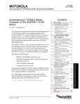
Emmanuel Roy, David Crawford, Iain Stirling
In the rapidly evolving arena of telecommunications, the need for
digital signal processors (DSPs) with ever greater performance
continually leads to new high technology, low-cost devices with
low power consumption and dissipation. The
DSP56307/DSP56311 processors are recent powerful additions to
Motorola’s high performance DSP56300 family of
DSPs [1],[2],[4]. Although the DSP56307/DSP56311 specifically
target the telecommunications marketplace, they are also ideally
suited as general-purpose devices.
Among the innovative features of the DSP56307/DSP56311
processors is a dedicated filtering hardware unit, the Enhanced
Filtering Coprocessor (EFCOP), that can potentially double the
overall speed performance. High-level programming languages
such as C and C++ greatly simplify the processors’ programing
tasks (including the EFCOP), making the DSP56307/DSP56311
processors accessible to any engineer, from DSP novices to DSP
experts. The combination of high processing performance and the
ability to program in high-level languages eases
DSP56307/DSP56311 implementation, reduces application
development time, and improves code readability and
maintenance.
Contents
1
2
Programming Examples ......... 2
EFCOP Overview .................... 2
2.1
2.2
EFCOP Modes ................................. 4
EFCOP Programming Model .......... 4
3
TASKING Tool Suite .............. 8
3.1
File Requirements for Programming
the EFCOP ...................................... 8
FDM and FCM Source Code
Declaration .................................... 10
EFCOP Register Access in
TASKING C.................................. 10
3.2
3.3
4
Transferring Data to and
from the EFCOP.................... 11
4.1
4.2
4.3
Polling............................................ 12
Direct Memory Access (DMA) ..... 13
Interrupts........................................ 17
5
6
EFCOP Initialization Mode. 19
Application Examples ........... 20
6.1
6.2
6.3
6.4
Software Installation and Concepts21
FIR Filter ....................................... 21
Adaptive FIR filter......................... 24
Residu Function from the GSM
EFR/AMR Vocoders27
7
DSP56311EFCOPandDSP56307
EFCOP Compared ................ 29
References .............................. 29
8
This application note examines the EFCOP modes of operation
and explains how to configure and activate these modes from C
using TASKING’s Tool Suite for the DSP56300 family [6]. The
code was developed and tested on a DSP56307 evaluation
module, but the development approach, the EFCOP concepts, and
the C code examples provided here apply equally to the
DSP56311. The minor differences between the DSP56311
EFCOP and the DSP56307 EFCOP are stated in Section 7.
Finally, we recommend that you read this application note in
conjunction with Chapter 10 of the DSP56307 User’s Manual,
“Enhanced Filter Coprocessor” [1].
© Freescale Semiconductor, Inc., 2004. All rights reserved.
For More Information On This Product,
Go to: www.freescale.com
Programming the DSP56307/DSP56311
EFCOP in C
Programming the
DSP56307/DSP56311 EFCOP in C
Using TASKING’s Tool Suite
Order Number: AN2108/D
Rev. 0, 5/2001
Freescale Semiconductor, Inc.
EFCOP Overview
1
Programming Examples
Accompanying this application note are files containing examples of typical filtering configurations. Each
example presents an overview of relevant theory, a description of implementation issues and techniques,
and a C code example. You can obtain a zipped file containing all files required to run the examples from
http://www.mot.com/SPS/DSP/documentation/appnotes.html. This code was tested with the
TASKING C/C++ for DSP563xx 2.2, Rev. 2 tool chain running under Windows NT 4.0 and Windows 98.
The CrossView Pro Debugger runs the code on a DSP56307EVM.
2
EFCOP Overview
Freescale Semiconductor, Inc...
The DSP56307 EFCOP is a dedicated filtering hardware unit that implements many standard
filtering structures. It contains an independent filtering multiply and accumulate (MAC) unit, giving the
DSP56307 dual MAC capability. It operates concurrently with the DSP56300 core, giving the DSP56307
a maximum potential performance of 200 Million Instruction per Second (MIPS).
The EFCOP supports two basic filtering architectures: Finite Impulse Response (FIR) and all-pole Infinite
Impulse Response (IIR). These architectures can be combined to form a pole-zero IIR filter. The EFCOP
architecture also has an adaptive FIR filtering mode with a flexible coefficient update mechanism that
allows a range of adaptive algorithms to be used—for example, the Least Mean Square (LMS) algorithm,
the Normalized LMS, and customized update algorithms. However, an adaptive IIR mode is not
supported. The EFCOP also runs in Multichannel mode with up to 64 FIR/IIR filters.
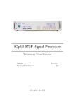
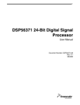
We use the EFCOP to process data samples as shown in Figure 1. Input data samples are taken from the
DSP56307 internal memory, the EFCOP filters the data, and the output data samples are stored back into
internal memory. Although we use internal memory in the applications discussed here, external memory
could also be used if desired.
Input
Signal
y0
y1
y2
...
x0
x1
x2
x3
...
Filtered
Signal
EFCOP
X/Y Memory
X memory
Y memory
X/Y Memory
Shared Memory
DSP56300 Core access
Figure 1. EFCOP Usage
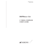
A block diagram of the EFCOP architecture is shown Figure 2.
2
Programming the DSP56307/DSP56311 EFCOP in C
For More Information On This Product,
Go to: www.freescale.com
Freescale Semiconductor, Inc.
EFCOP Overview
Alongside the dedicated FMAC unit, the DSP56307 EFCOP (see Figure 2) uses two memory data banks:
•
Filter Data Memory (FDM). Contains the filter input samples. This bank of memory is mapped to
the bottom 4K words of the X data memory space.
•
Filter Coefficient Memory (FCM). Contains the filter coefficients. This bank of memory is mapped
to the bottom 4K words of the Y data memory space.
Freescale Semiconductor, Inc...
The dual X and Y memory banks allow a simultaneous fetch of both the input sample and its corresponding
filter coefficient, so a complete MAC operation can be carried out in a single clock cycle. The X and Y
memory banks allocated to the EFCOP (and shared with the DSP56300 core) are each 4K x 24 bits so that
filters with up to 4096 coefficients can be implemented. In Multichannel mode, the maximum number of
coefficients for each filter is 4096/N, where N is the number of filters being implemented. For example, for
N=64 (which is the maximum value of N), each filter can have up to 64 coefficients.
DMA BUS
PMB
Interface
GDB BUS
FDIR
FCNT
Filter Count
4-Word
Data Input Buffer
Control
Logic
FCM
FCBA
Coefficient Base
FDM
Data
Memory Bank
24-bit
X Memory
FKIR
Filter Constant
Y Memory
FDBA
Data Base
Coefficients
Memory Bank
24-bit
Address
Generator
FMAC
24x24 → 56-bit
Rounding and Limiting
Output Buffer
FDOR
Figure 2. DSP56307 EFCOP Block Diagram
Programming the DSP56307/DSP56311 EFCOP in C
For More Information On This Product,
Go to: www.freescale.com
3
Freescale Semiconductor, Inc.
EFCOP Overview
2.1 EFCOP Modes
The EFCOP operates in several different modes, making it very flexible:
•
FIR filtering:
— with real taps
— with complex taps generating a complex output (that is, real and imaginary) for each complex
input
— with complex taps generating alternate real and imaginary outputs
— in magnitude mode (calculate the power of the input signal)
Freescale Semiconductor, Inc...
Note that decimation and input scaling can be used with these modes.
•
Adaptive FIR filtering.
•
Multichannel FIR filtering. Note that decimation cannot be used with this mode.
•
All-pole IIR filtering. Note that input/output scaling can be used with this mode.
•
Multichannel all-pole IIR filtering. Note that decimation cannot be used with this mode.
•
Initialization or non-initialization of the EFCOP data buffer.
•
Data transfer using polling, DMA, or interrupts.
•
Several arithmetic options:
— Two’s complement rounding, convergent rounding or no rounding
— 16-bit arithmetic mode
— Arithmetic saturation
Examples in this application note include the following:
•
Use of the FIR and Adaptive FIR modes
•
Initialization and non-initialization modes
•
24- and 16-bit arithmetic modes
•
Saturation mode
•
Convergent and two’s complement rounding modes
•
Polling, DMA, and interrupt methods of data transfer
2.2 EFCOP Programming Model
The EFCOP uses the FDM and FCM to store input data and filter coefficients. EFCOP operation is
controlled and monitored by nine memory mapped I/O registers (mapped in Y data memory), as listed in
Table 1.1
1. For details on the function of these registers, consult the EFCOP chapter in the DSP56307 User’s Manual.
4
Programming the DSP56307/DSP56311 EFCOP in C
For More Information On This Product,
Go to: www.freescale.com
Freescale Semiconductor, Inc.
EFCOP Overview
Table 1. EFCOP Memory Usage
Freescale Semiconductor, Inc...
Address
Name
Y:$FFFFB0
Filter Data Input Register (FDIR)
Y:$FFFFB1
Filter Data Output Register (FDOR)
Y:$FFFFB2
Filter K-Constant Input Register (FKIR)
Y:$FFFFB3
Filter Count Register (FCNT)
Y:$FFFFB4
Filter Control/Status Register (FCSR)
Y:$FFFFB5
Filter ALU Control Register (FACR)
Y:$FFFFB6
Filter Data Buffer Base Address (FDBA)
Y:$FFFFB7
Filter Coefficient Buffer Base Address (FCBA)
Y:$FFFFB8
Filter Decimation/Channel Register (FDCH)
X:$0 .. X:$FFF
Filter Data Memory Bank (FDM)
Y:$0 .. Y:$FFF
Filter Coefficient Memory Bank (FCM)
Table 2 lists the basic steps in programming the EFCOP, along with the register(s) involved in each step.
Table 2. Overview of Steps in Programming the EFCOP and Its Registers
Step
Register
Disable the EFCOP.
Filter Control/Status Register (FCSR) FEN = 0
Before filtering begins, the DSP56300 core does the
following:
Initialize the control and status register and the ALU
control register.
Point to the start of the FCM.
Point to the start of the FDM.
Initialize the FCM buffer with the coefficients. Copy the
coefficients from the DSP56300 core to the FDM bank,
in reverse order.
Filter Control/Status Register (FCSR) and
Filter ALU Control Register (FACR)
Filter Coefficient buffer Base Address (FCBA)
Filter Data Buffer Base Address (FDBA)
EFCOP Coefficient Buffer Base Address Register (FCBA)
Filter Data Buffer Base Address (FDBA)
Initialize the counter to N-1, where N is the length of
the filter.
Initialize the decimation/channel count.
Configure the EFCOP operation mode.
Filter Count Register (FCNT)
Decimation/Channel Count Register (FDCH)
NOTE: The coefficients must be stored in reverse
order with respect to the input samples.
Enable the EFCOP.
Filter Control/Status Register (FCSR) FEN = 1
Programming the DSP56307/DSP56311 EFCOP in C
For More Information On This Product,
Go to: www.freescale.com
5
Freescale Semiconductor, Inc.
EFCOP Overview
Table 2. Overview of Steps in Programming the EFCOP and Its Registers
Step
Register
After the EFCOP has been triggered to begin filtering:
Input data samples are fed into the EFCOP to trigger it
into calculating output samples.
Filter Data Input Register (FDIR)
Freescale Semiconductor, Inc...
The input samples can be transferred from a separate
buffer in memory or from a memory-mapped peripheral
register (for example, A/D converter). Input samples
can be transferred one, two, three, or four words at a
time, since the FDIR is four words deep. The EFCOP
automatically stores these input samples in the FDM
buffer, which is essentially a circular buffer of length N.
This ensures that the EFCOP has access to the N
most recent data samples, which are required to calculate the corresponding output sample.
The output sample is placed into the output register.
Once an output sample is available in the FDOR, it
must be read from the FDOR and can then be stored in
memory or sent to a memory-mapped peripheral register (for example, a D/A converter). Data transfers to
and from the EFCOP are initialized using polling, DMA,
or interrupts. These methods for transferring samples
from memory to the FDIR and from the FDOR to memory are discussed in Section 4 .
Filter Data Output Register (FDOR)
It is also important to note the location of the data samples and filter coefficients in the EFCOP memory
banks. Figure 4 represents both memory banks at an
arbitrary time, k, where x(k) is the most recent input
sample, wi are the filter coefficients and N is the filter
length. Note that for the next iteration, FDBA will have
advanced by one word, and the filtering calculation will
involve a wrap-around. Therefore, the value held in
FDBA varies as time progresses.
Filter Data buffer Base Address (FDBA)
NOTE: The EFCOP manages the value of FDBA and
the placement of data samples in FDM. The programmer need only be concerned with feeding values to the
FDIR
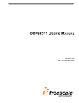
Figure 3 depicts the EFCOP operational model, and Figure 4 shows how data is stored in the EFCOP.
6
Programming the DSP56307/DSP56311 EFCOP in C
For More Information On This Product,
Go to: www.freescale.com
Freescale Semiconductor, Inc.
EFCOP Overview
FCNT
FCBA
FDBA
Address
Generator
Freescale Semiconductor, Inc...
Automatic
Transfer
Input
Samples
FDM
Memory
X:$0 ... X:$FFF
FCM
Memory
Y:$0 .. Y:$FFF
FMAC
FDIR
DSP56300 Core Access
(Filter Coefficients)
FDOR
Figure 3. EFCOP Modes of Operation
High
Address
FDBA
+ FCNT-1
FDM
FCM
x(k)
w0
x(k-1)
w1
.
.
.
.
.
FCBA+FCNT
.
Low
Address
wN-3
FDBA+1
FDBA
x(k-N+2)
wN-2
x(k-N+1)
wN-1
FCBA+1
FCBA
EFCOP
Calculation
Figure 4. Storing Data Into the EFCOP Data and Coefficient Memory Banks
In summary, programing the EFCOP generally involves the following steps:
1. Disable the EFCOP by resetting the FEN bit of the Control/Status (FCSR) register.
2. Initialize the EFCOP FCSR and ALU (FACR) registers.
3. Initialize the EFCOP Filter Count (FCNT) register with the filter length-1.
4. Initialize the EFCOP Data buffer Base Address (FDBA).
5. Initialize the EFCOP Coefficient buffer Base Address (FCBA) register.
Programming the DSP56307/DSP56311 EFCOP in C
For More Information On This Product,
Go to: www.freescale.com
7
Freescale Semiconductor, Inc.
TASKING Tool Suite
6. Initialize the Decimation/Channel Count (FDCH) register.
7. Initialize the EFCOP filter coefficients (copy from the DSP56300 core to the FDM bank, in reverse
order).
8. Enable the EFCOP (set the FEN bit of the FCSR).
9. Initialize data transfers to and from the EFCOP (using polling, DMA or interrupts).
Freescale Semiconductor, Inc...
3
TASKING Tool Suite
TASKING’s DSP563xx Tool Suite is a high-level development system that implements high-level
language applications (C/C++) and runs them efficiently on the DSP56300 family of processors. You can
use the highly flexible TASKING Tools Suite to program the DSP peripherals, DSP interrupt service
routines, DMA transfers and, for the DSP56307/DSP56311, the EFCOP. The TASKING Tools Suite is
accessed from the TASKING Embedded Development Environment (EDE). It includes a compiler,
assembler, linker, locator, and debugger. Figure 5 shows the overall suite, which is customized for the
application discussed here. The examples in this document are all implemented from the EDE and run on a
DSP56307 Evaluation Module (EVM).2
3.1 File Requirements for Programming the EFCOP
The TASKING Tools Suite uses different configuration files depending on the target hardware. These files
are “description” files that define device-specific attributes such as memory sizes, speed, and so on. They
also define sections and locate the program and data words of an application into memory. For the
DSP56307EVM, the TASKING-defined description files are 56307evm.dsc, 56307evm.cpu, and
56307evm.mem.3 These files are for general-purpose use of the DSP56307 processor and do not provide
for use of the EFCOP because some applications do not need a dedicated filter coprocessor. To use the
EFCOP, you need the following slightly modified versions of these files:
•
Efcopdma.dsc
•
Efcopdma.cpu
•
Efcopdma.mem
TASKING provides these EFCOP description files. The key modifications pertain to the section location
of the FDM and FCM buffers in the bottom 4K of memory at a modulo 2 address—for example, “section
.xbssFDM_buffer” and “section .ybss.FCM_buffer,” which reside in the description file Efcopdma.dsc.
All examples in this application note use the three Efcopdma.xxx files, and these files must be included
into the application environment. To use these description files, you must set up the linker options in the
EDE environment as follows:
•
Target Hardware configuration: DSP56307, Unified Memory Map
•
Select Use Project specific locator control file, and write efcopdma.
2. For details on TASKING, contact [6]. For details on the EDE tools suite, refer to [6],[7], and [8].
3. For details on the description files, refer to [7].
8
Programming the DSP56307/DSP56311 EFCOP in C
For More Information On This Product,
Go to: www.freescale.com
Freescale Semiconductor, Inc.
TASKING Tool Suite
C files
.c
C
Pre-processor
and
C compiler
c563
Assembler
as563
TASKING STeering Program: CC563
Freescale Semiconductor, Inc...
Assembly
files
.src
Relocatable
object files
.obj
Linker
lk563
Object files
.out
Locator
lc563
Absolute
files
.abs
TASKING
Cross View
37
Command
Convertor
ONCE/JTAG
Debugger
DSP56307 EVM
RS232
Figure 5. Overview of TASKING Tools Suite
Programming the DSP56307/DSP56311 EFCOP in C
For More Information On This Product,
Go to: www.freescale.com
9
Freescale Semiconductor, Inc.
TASKING Tool Suite
3.2 FDM and FCM Source Code Declaration
The FDM and FCM must be declared as arrays in the C source code with two specific names, FDM_buffer
and FCM_buffer, respectively. These names coincide with the section name declarations in the
description file. Also, the FDM and FCM buffers must match the fractional data
format of the DSP56300 family architecture and be placed in X and Y memory, respectively. To
achieve this match, use the _fract data type specifier and the _X and _Y memory specifiers.
Finally, the FDM and FCM must be modulo buffers and therefore the compiler must place the
two arrays, FDM_buffer and FCM_buffer, at modulo N addresses; this is achieved using the _circ
Efcopdma.dsc
Freescale Semiconductor, Inc...
specifiers. The overall declaration is represented as follows:
_fract _X _circ FDM_buffer [FIR_FILTER_LENGTH] ;
_fract _Y _circ FCM_buffer [FIR_FILTER_LENGTH] ;
The correct memory mapping of the EFCOP array definition (that is, FDM_buffer and FCM_buffer) is the
result of the combination of the array definition explained here and the configuration specified in
Efcopdma.dsc. The EDE automatically generates these section names, which are expected by the
Efcopdma.dsc description file. If the described procedure is followed, the EFCOP arrays declared are
placed in shared (EFCOP/core) memory (that is, X:$0 .. X:$FFF and Y:$0 .. Y:$FFF). All arrays and
variables declared with any other names are placed in shared DMA/core memory (namely, X:$1000... and
Y:$1000...) unless the description file is modified to specify different section location addresses.
3.3 EFCOP Register Access in TASKING C
To facilitate reading and writing the EFCOP registers in C, TASKING provides a header file for the
DSP56307 processor (reg56307.h) that defines a memory map of all the DSP registers, including
peripherals. Each declaration is based on the combination of unions and structures of bit fields that allow
access to a complete register or to individual bits within a register. These unions have two members:
•
I, a 24-bit integer.
•
B, a group of bit fields totalling 24 or 16 bits.
For instance, the union for the EFCOP Filter ALU Control Register (FACR) is:
typedef union /* EFCOP ALU Control Register */
{
struct
{
10
unsigned
unsigned
int
int
FSCL
FRM
FSM
FSA
int
int
FISL
:
:
:
:
2;
2;
1;
1;
/*
/*
/*
/*
0:
2:
4:
5:
Filter Scaling */
Filter Rounding Mode */
Filter Saturation Mode*/
Filter 16-bit Arithmetic
Mode */
: 1; /* 6: Filter Input Scale */
:17; /* 7: Reserved */
Programming the DSP56307/DSP56311 EFCOP in C
For More Information On This Product,
Go to: www.freescale.com
Freescale Semiconductor, Inc.
Transferring Data to and from the EFCOP
} B;
int I;
}facr_type;
This union is then defined as follows, which allows direct register access from the C code:
#define FACR (*(facr_type _Y *)0xFFFFB5)
/* EFCOP ALU Control
Register*/
Two different union accesses are possible:
•
Using the ‘I’ member of the union for word access. This method accesses the complete register and
generates a single MOVEP instruction (two program words):
Freescale Semiconductor, Inc...
FACR.I = 0x000001;
•
Using the ‘B’ member of the union for bit field access. This method accesses individual bits and
generates BSET and BCLR instructions. This method is not as efficient as the first one since more
program words are used. However, it makes the code more readable and is useful while the code is
developed and debugged:
FACR.B.FISL = 0x0;
FACR.B.FSA = 0x0;
FACR.B.FSM = 0x1;
FACR.B.FRM = 0x0;
FACR.B.FSCL = 0x0;
4
/* Enable Filter Saturation */
/*
/*
/*
/*
/*
Filter
Do not
Enable
Choose
Choose
Input Scale (applicable only in IIR mode).*/
enable Sixteen-bit Arithmetic Mode.*/
Filter Saturation. */
rounding mode = convergent.*/
Filter Scaling = 1 (no scaling).*/
Transferring Data to and from the EFCOP
The input data samples must be transferred from memory to the EFCOP data input register (FDIR).
Similarly, the output data samples must be transferred from the EFCOP data output register (FDOR) to
memory, as shown in Figure 6.
EFCOP
FDIBE
FDOBF
Input
Signal
x(0)
x(1)
x(2)
x(3)
x(4)
x(5)...
...
...
X/Y Memory
Transfer To
Transfer From
FCSR
FDOR
FDIR
FMAC
FDM
FCM
Filtered
Signal
y(0)
y(1)
y(2)
y(3)
...
...
...
...
X/Y Memory
Figure 6. Transfer to and from the EFCOP Registers
Programming the DSP56307/DSP56311 EFCOP in C
For More Information On This Product,
Go to: www.freescale.com
11
Freescale Semiconductor, Inc.
Transferring Data to and from the EFCOP
These transfers are accomplished using either polling, DMA, or interrupts. All the different transfers rely
on two status bits from the FCSR:
•
Filter Data Input Buffer Empty (FDIBE) bit
•
Filter Data Output Buffer Full (FDOBF) bit
The method for transferring data from memory to the FDIR need not be the same as the one for
transferring data from FDOR to memory. Any combination of the methods can be used. For example,
transfers to the FDIR can use a DMA channel while transfers from the FDOR can use interrupts.
Freescale Semiconductor, Inc...
Note:
The FDIR register is a 4-word deep FIFO buffer, so one to four words can be written to the FDIR
at a time. In this application note, 4-word transfers are used.
4.1 Polling
With the polling method of data transfer, the core polls a status bit in the EFCOP FCSR to determine when
it can transfer a data sample to or from the EFCOP. The status bit polled depends on whether data is to be
transferred from memory to the FDIR or from the FDOR to memory:
•
For transfers from memory to FDIR, the FDIBE bit (which is set when the FDIR is empty) is
polled.
•
For transfers from FDOR to memory, the FDOBF (which is set when the FDOR contains a valid
output data sample) is polled.
Recall that the filter buffer status bits, FDIBE and FDOBF, are directly accessed by FCSR.B.FDIBE and
FCSR.B.FDOBF. The following code segment illustrates the use of polling for both writing to the FDIR
and reading from the FDOR. This code is contained in a file named Transfer_by_Polling.c.
Example 1. Use of Polling for Transferring Data
main()
{
/* Initialize data buffers, input[] and output[] */
/* Copy filter coefficients to FDM */
/* Initialize EFCOP -- Select arithmetic modes, operating
modes, number of channels, etc. */
FCSR.B.FEN = 1; /* Enable EFCOP */
for (n=0; n<NUMBER_OF_SAMPES; n++)
{
/*** Poll FDIBE until set ***/
while (FCSR.B.FDIBE == 0)
{}
/* Wait for FDIBE to become 1 */
FDIR = input[n]; /* Feed data sample to FDIR */
12
Programming the DSP56307/DSP56311 EFCOP in C
For More Information On This Product,
Go to: www.freescale.com
Freescale Semiconductor, Inc.
Transferring Data to and from the EFCOP
/**********************************************/
/*** EFCOP is now calculating output sample ***/
/**********************************************/
/*** Poll FDOBF until set ***/
while (FCSR.B.FDOBF == 0)
{}
/* Wait for FDOBF to become 1 */
output[n] = FDOR; /* Get output data sample from EFCOP */
} /* Repeat for next iteration */
Freescale Semiconductor, Inc...
} /* End of main() */
Although polling is the simplest method of transferring data to and from the EFCOP, it suffers from the
disadvantage that the DSP56300 core waits in a “do-nothing” loop for the status bit to change. The
DSP56300 core is therefore unavailable for performing other tasks. Polling is useful for testing the EFCOP
configuration and verifying the proper functionality of an application. However, for greater efficiency,
other methods of data transfer that involve the DSP56300 core as little as possible are preferred.
4.2 Direct Memory Access (DMA)
DMA transfers input data samples from memory to the FDIR or output data samples from the FDOR to
memory without requiring intervention from the DSP56300 core. The DSP56307 has six DMA channels,
any of which can be used. A DMA transfer using DMA Channel n involves the registers shown in Table 3.
In addition to these general DMA registers, the appropriate DMA offset registers must be used.
.
Table 3. DMA Registers
Register (n=0 .. 5 )
Name
Purpose
DCRn
DMA Control Register
Sets the DMA modes required.
DSRn
DMA Source address Register
Contains address of source data for DMA transfer.
DDRn
DMA Destination address Register
Contains address of destination for DMA transfer.
DCOn
DMA Counter Register
Contains number of items to be transferred.
For DMA transfers from memory to the FDIR, set up the DMA channel to be triggered by FDIBE; for
DMA transfers from FDOR to memory, set up the DMA channel to be triggered by FDOBF. Issue DMA
requests via internal peripheral DMA requests MDRQ11 and MDRQ12, respectively, as shown in Table 4.
.
Table 4. DMA Request Sources.
Request Condition
Peripheral Request Number
DCR Bits 15-11 (DSR [4–0])
FDIBE=1
MDRQ11
10101
FDOBF=1
MDRQ12
10110
Programming the DSP56307/DSP56311 EFCOP in C
For More Information On This Product,
Go to: www.freescale.com
13
Freescale Semiconductor, Inc.
Transferring Data to and from the EFCOP
The appropriate DMA channel should be set to respond to requests from MDRQ11 or MDRQ12,
as required. The EFCOP always generates DMA requests when FDIBE or FDOBF are set. However, a
DMA transfer occurs only if the appropriate DMA channel is configured to respond to such a request. If
DMA transfers are used for both input and output, two DMA channels are required.
The DMA controller cannot be used to access memory locations below 4K ($1000), since the EFCOP uses
this memory area for its coefficient and data buffers (FCM and FDM). This is true even when the EFCOP
is not used. Memory below 4K is connected to the EFCOP instead of the on-device DMA controller, so
only the EFCOP or the DSP56300 core can assess it.4
4.2.1 EFCOP DMA Input
Freescale Semiconductor, Inc...
For the application discussed here, four words are written to the FDIR each time. A two-dimensional (2-D)
DMA transfer to the EFCOP is also used. This type of transfer moves four words into the FDIR on each
DMA request (as shown in Figure 7). A 1-D DMA channel could also be used without penalty (see [4]).
Using a 2-D DMA transfer, four words are transmitted each time a trigger from the EFCOP is received
until the length of the input sequence is reached. The only “trick” is to set the DMA offset register, DORx,
to one. The configuration principles behind this 2-D transfer are as follows:
•
DMA Control Register (DCR):
— DMA Transfer Mode (DTM) = line transfer triggered by request
— DMA Request Source (DRS) = MDRQ11 (see Table 3-4)
— DMA Address Mode (DAM)
— Source, 2-D counter mode B, offset DOR0
— Destination. No update, no offset7
•
DMA Counter Register (DCO):
— in mode B: DCOL=3, DCOH= ((number of 4-word blocks required)-1)
•
DMA Offset Register (DOR0): set to 1.
Input samples
x(0)
+1
x(1)
+1
x(2)
x(3)
+1
+DOR0
+1
+1
+1
Transfer to FDM
EFCOP
x(4)
x(5)
...
...
FDIR
X/Y Memory
Figure 7. Four-Word Deep FDIR Access Using DMA
4. For details on DMA, refer to [4] and [5].
14
Programming the DSP56307/DSP56311 EFCOP in C
For More Information On This Product,
Go to: www.freescale.com
Freescale Semiconductor, Inc.
Transferring Data to and from the EFCOP
4.2.2 EFCOP DMA Output
Since the EFCOP output register, FDOR, is one word deep, a 1-D DMA transfer from the EFCOP is
necessary. This type of transfer moves one word from the FDOR on each peripheral request.
Example 2. DMA Transfer from Memory to the FDIR
/* --------------------------------------------------------------------------------- *
*
Set up DMA Channel 0 to transfer input data to EFCOP’s FDIR *
* -------------------------------------------------------------------------------- */
/* DMA Counter 0: transfer of 25 * 4 items (counter mode B) */
Freescale Semiconductor, Inc...
DCO0 = 0x018003;
/* Source address = start of input data buffer */
DSR0 = (int*) input;
/* Destination address = EFCOP’s FDIR */
DDR0 = (int*)&FDIR;
/* DMA Offset Regsiter 0 */
DOR0 = 1;
/* Offset = 1 */
/* DMA Ch0 Control Register */
DCR0.I = 0x14AA04;
/* DE
= 0
(DMA Ch0 disabled for now )
*/
/* DIE
= 0
(No interrupt at end of transfer
*/
/* DTM
= 010
(Line transfer (2D), Clear DE
*/
/* DPR
= 10
(Priority = 2)
*/
/* DCON = 0
(Continuous mode not needed )
*/
/* DRS
= 10101
(DMA Request: MDRQ11: EFCOP FDIBE) */
/* D3D
= 0
(Disable 3D mode)
/* DAM
= 100000
(DMA Addressing Mode:
*/
Source = 000 (2D, DOR0 offset)
Dest
= 100 (No update)
)
*/
/* DDS
= 01
(Destination (FDIR) is in Y memory)
*/
/* DSS
= 00
(Source (input[]) is in X memory)
*/
Programming the DSP56307/DSP56311 EFCOP in C
For More Information On This Product,
Go to: www.freescale.com
15
Freescale Semiconductor, Inc.
Transferring Data to and from the EFCOP
The configuration principles are as follows:
•
DMA Control Register (DCR):
— DMA Transfer Mode (DTM) = word transfer triggered by request
— DMA Request Source (DRS) = MDRQ12 (see Table 3-4)
— DMA Address Mode (DAM)
— Source - 1D counter mode B, offset DOR0
— Destination - Selected by the user.
•
DMA Counter Register (DCO):
Freescale Semiconductor, Inc...
— DCO0 = (number of samples-1)
A 1-D DMA transfer from the FDOR register to memory programming example follows.
Example 3. DMA Transfer from FDOR to Memory
/* ------------------------------------------------------------------------------------ *
* Set up DMA Channel 1 to transfer output data to EFCOP’s FDOR *
* ----------------------------------------------------------------------------------*/
/* DMA Counter 1: transfer of 81 items (counter mode A) */
DCO1 = (INPUT_LENGTH - FIR_LENGTH);
/* Note: DCO1 = (No. items) - 1 */
/* Source address = EFCOP’s FDOR */
DSR1 = (int*)&FDOR;
/* Destination address = start of output data buffer */
DDR1 = (int*)output;
/* Offset = 1 */
/* DMA Ch1 Control Register */
DCR1.I = 0x0CB2C1;
/* DE
= 0 (DMA Ch1 disabled for now )
*/
/* DIE
= 0 (No interrupt at end of transfer)
*/
/* DTM
= 001(Word, Clear DE
*/
/* DPR
= 10 (Priority = 2)
*/
/* DCON = 0(Continuous mode not needed
*/
/* DRS
= 10110(DMA Request is MDRQ12: EFCOP FDOBF) */
/* D3D
= 0(Disable 3D mode)
/* DAM
= 101100 (DMA Addressing Mode:
*/
Source = 100 (No update)
Dest
16
= 101 (Post Inc by 1)
) */
Programming the DSP56307/DSP56311 EFCOP in C
For More Information On This Product,
Go to: www.freescale.com
Freescale Semiconductor, Inc.
Transferring Data to and from the EFCOP
/* DDS
= 00
(Dest (output[]) is in X memory)*/
/* DSS
= 01
(Source (FDOR) is in Y memory)*/
4.2.3 DMA and DSP56300 Core Interaction
Freescale Semiconductor, Inc...
The DSP56300 core sets up the DMA channels. Then the EFCOP processes all of the data samples with no
core intervention, freeing the DSP56300 core to perform other tasks. The DSP56300 core uses two
different ways to check whether all samples have been processed:
•
Polling. The DSP56300 core checks the DMA Transfer Done (DTD) bit for the appropriate DMA
channel in the DMA Status Register (DSTR). This bit is cleared (by writing a one to it) when the
DMA transfer completes.
•
Interrupts. If the DMA Interrupt Enable (DIE) bit is set (bit 22 of the DCRx register), an interrupt
occurs when the DMA transfer completes.
In both cases, the DMA channel that is polled or configured to generate an interrupt at the end of the DMA
transfer is normally the channel used to transfer data from the FDOR to memory, since this is the last DMA
transfer to take place.
4.3 Interrupts
The third method of transferring data to or from the EFCOP is to set the FDIBE or FDOBF bit of the FCSR
register to generate interrupts. Unlike the DMA, the FDIBE and FDOBF bits do not generate interrupt
requests unless the EFCOP is configured to do so. Interrupt service routines that service the appropriate
interrupt request to perform the data transfer must be written and configured.
The interrupt method of data transfer requires DSP56300 core intervention, since the DSP56300 core must
stop its current activity to service the interrupt request. However, unlike polling, the use of interrupts does
not require the core to wait in a “do-nothing” loop until FDIBE or FDOBF becomes set. The following
steps set up the interrupts for EFCOP data transfers:
1. Set the interrupt mask bits, (bits 8 and 9) in the Status Register (SR). These bits determine which
priorities of interrupt are masked.
2. Set the priority levels of the EFCOP (bits 10 and 11 of the Interrupt Priority Register Peripheral
(IPRP)). These priority levels should have a sufficiently high priority that they are not masked by the
interrupt mask priority setting in bits 8 and 9 of the Status Register. Setting the interrupt priority level
is application-dependent since other interrupts may be in use elsewhere in the system.
3. Enable interrupt generation bits in the EFCOP status register (FCSR). Setting bit 10 (FDIIE) enables
interrupt generation when the FDIR becomes empty; setting bit 11 (FDOIE) enables interrupt
generation when the FDOR becomes full.
Programming the DSP56307/DSP56311 EFCOP in C
For More Information On This Product,
Go to: www.freescale.com
17
Freescale Semiconductor, Inc.
Transferring Data to and from the EFCOP
Table 5 and Table 6 list the priorities corresponding to these settings.
Freescale Semiconductor, Inc...
Table 5. Status Register Interrupt Masks
Exceptions Permitted
Interrupt Priority Level
I1 = SR[8]
I0=SR[9]
0
0
IPL 0,1,2,3
0
1
IPL 1,2,3
1
0
IPL 2,3
1
1
IPL 3
Table 6. EFCOP Interrupt Priority Levels.
EFCOP Interrupt Priority
Level
E0L1=IPRP[10]
E0L0=IPRP[11]
0
0
IPL0
0
1
IPL1
1
0
IPL2
1
1
IPL3
In the vectored interrupt architecture of the DSP56307, up to 128 interrupt sources cause the processor to
jump to one of 128 program addresses. These addresses are two words apart, so if the interrupt can be
serviced using only two words of machine code, there is no need to jump to a larger interrupt service
routine. These interrupts are called fast interrupts. In many cases, however, the interrupt requires more
than two words of code. In these cases, the two words in the interrupt vector space contain a JMP
instruction to the location of the interrupt service routine. These interrupts are called long interrupts.
The actual address of a particular interrupt vector consists of the Vector Base Address (VBA), which is
stored in the VBA register, plus an offset corresponding to the particular interrupt source. For example, the
offset when the EFCOP Data Input Buffer is empty (FDIBE) is $68, and the offset when the EFCOP Data
Output Buffer is full (FDOBF) is $6A. The addresses are therefore VBA + $68 and VBA + $6A,
respectively [4].Table 7 shows the interrupt vectors for the EFCOP on the DSP56307.
Table 7. EFCOP Interrupt Vectors
18
Interrupt
Address
Interrupt
Number
Interrupt Vector
Priority
Interrupt Enable
Interrupt
Conditions
VBA + $68
52
Data input buffer empty
0–2
FDIIE=FCSR[10]
FDIBE=1
VBA + $6A
53
Data output buffer full
0–2
FDOIE=FCSR[11]
FDOBF=1
Programming the DSP56307/DSP56311 EFCOP in C
For More Information On This Product,
Go to: www.freescale.com
Freescale Semiconductor, Inc.
EFCOP Initialization Mode
In TASKING C, a function is declared as an interrupt service routine using the special type qualifiers
_long_interrupt and _fast_interrupt. If a function declared as a fast interrupt cannot be implemented in two
words or fewer, the compiler automatically changes the function to a long interrupt service routine. In this
application note, interrupts require more than two words of code, so only long interrupts are used.5 The
following code segments illustrate the use of the _long_interrupt type qualifier for two interrupt service
routines: one triggered by the EFCOP FDIBE condition, the other by the EFCOP FDOBF condition.
Example 4. Interrupt for FDIR
void _long_interrupt(52) input_isr(void);
{
/* Note: Interrupt number is $68 / 2 = $34 = 52 */
FDIR = *x_ptr++;
/* Load FDIR with next value */
Freescale Semiconductor, Inc...
}
Example 5. Interrupt for FDOR
void _long_interrupt(53) output_isr(void);
{
/* Note: Interrupt number is $6A / 2 = $35 = 53 */
*y_ptr++ = FDOR;
/* Get value from FDOR */
}
If the interrupt service routines must perform further tasks, such as error calculation for adaptive
algorithms, these tasks must be programmed within the routines.
5
EFCOP Initialization Mode
The EFCOP has two different filter initialization modes that are controlled by the Filter Processing
Initialization Mode (FPRC) bit of the FCSR. These modes “inform” the EFCOP of its processing starting
point, as follows (see Table 8):
•
Initialized data mode. The EFCOP starts processing once the FDM buffer is full.
•
Non-Initialized data mode. The EFCOP starts processing as soon as the FDIR receives the first
sample.
Table 8. EFCOP Initialization Modes
FPRC
EFCOP Operation
FPRC=0
Initialization mode
The EFCOP starts processing once the FDM is full. For an N tap filter, the first output is
generated after the Nth input is loaded into the FDIR.
FPRC=1
No Initialization
The EFCOP starts processing as soon as the first input sample is loaded into the FDIR.
The values already in FDM are used to calculate FDOR, so be careful to ensure that the
FDM has been initialized manually before loading the first input data into the FDIR.
5. The use of the _fast_interrupt and _long_interrupt type qualifiers is described in [7].
Programming the DSP56307/DSP56311 EFCOP in C
For More Information On This Product,
Go to: www.freescale.com
19
Freescale Semiconductor, Inc.
Application Examples
Figure 8 shows the EFCOP data memory in initialized data mode. Although the FDM contains previous
memory values, the initialization mode fills the memory by the amount specified in the counter register,
FCNT, before the EFCOP starts calculating the first output sample. That is, the first FCNT-1 samples are
input before any filtering calculation is performed.
FDBA
FDBA +1
Freescale Semiconductor, Inc...
FDBA+FCNT
FDM
Value
Value
Value
Value
Value
Value
Value
Value
FDM
FDBA
FDM
x(k)
x(k-1)
x(k-2)
x(k-3)
Value
Value
Value
Value
FDBA +1
FDBA+FCNT
FDBA
x(k)
x(k-1)
x(k-2)
x(k-3)
x(k-4)
x(k-5)
x(k-6)
x(k-7)
FDBA+1
FDBA+FCNT
FDM
Initialization
completed,
EFCOP
starts processing
Automatic
Four Input Samples
FDIR
FDI
FDI
FDI
Input Samples
Transfer
FDIR
FDI
FDI
FDI
Figure 8. EFCOP Data Memory in Initialized Data Mode
Figure 9 shows the EFCOP Data memory in non-initialized data mode: as soon as the first data samples
are written into FDIR, the EFCOP starts processing. If this mode is used, it is often worth initializing the
initial data samples (i.e. “value”) in FDM to zero.
FDBA+1
FDBA
FDBA+FCNT
FDM
Value
Value
Value
Value
Value
Value
Value
Value
Four Input Samples
FDM
FDBA
FDBA+1
FDBA+FCNT
x(k)
x(k-1)
x(k-2)
x(k-3)
Value
Value
Value
Value
Data
received by FDM,
EFCOP starts
processing
FDIR
FDI
FDI
FDI
Figure 9. EFCOP Data Memory in Non-initialized Data Mode
6
Application Examples
Three application examples illustrating the use of the EFCOP are presented in this section, along with the
C source code for each application:
20
•
A Finite Impulse Response (FIR) filter
•
An Adaptive FIR filter using the Least Mean Square (LMS) algorithm
•
The Residu function from the Enhanced Full Rate (EFR) vocoder (an FIR filtering process)
Programming the DSP56307/DSP56311 EFCOP in C
For More Information On This Product,
Go to: www.freescale.com
Freescale Semiconductor, Inc.
Application Examples
6.1 Software Installation and Concepts
Create a directory for the software (for example, DSP56307), unzip the EFCOP_examples.zip file, and
extract the software into the DSP56307 directory. This operation creates three directories called
efcop_fir, efcop_firlms, and efcop_residu. Within each directory, two subdirectories are created:
out and tvecs, as represented in Figure 10.
efcop_fir
out
tvecs
Freescale Semiconductor, Inc...
DSP56307
efcop_firlms
out
tvecs
efcop_residu
out
tvecs
Figure 10. Directory Structure for the Filtering Examples
Each directory contains the C source file(s) and the files required for program configuration,
Efcopdma.cpu, Efcopdma.dsc, and Efcopdma.mem. After creating a project for each application,
perform the following operations:
1. Include the C file(s) in the project, as appropriate.
2. Set the DSP56307 EVM as the target DSP (within the EDE pull-down menu, Linker/Locator
Options/Target Hardware).
3. Within the same menu, click on Use Project Specific Locator Control File and type Efcopdma into
the window.
The application is now ready to compile,6 and if the compilation is successful, the CrossView Pro [8]
high-level debugger can be launched to run the code on the DSP56307 EVM. The application reads input
samples from existing data files in the tvecs directory and stores the filtered results in output files in the
out directory. These output files can then be compared to reference output files in tvecs to verify the
application results. However, this process is specific to each application and is therefore further explained
in the relevant sections that follow.
6.2 FIR Filter
In an FIR filter implementation using the EFCOP, to minimize DSP56300 core intervention, the DMA
controller feeds the input data samples to the EFCOP and retrieves output data samples from the EFCOP.
The DSP56300 core is used only to set the EFCOP and the DMA modes and then to activate them.7 The
6. The C Code for this example (fir.c) is listed in Appendix A.
7. See Section 4, Transferring Data to and from the EFCOP, on page 11 for details on the DMA approach.
Programming the DSP56307/DSP56311 EFCOP in C
For More Information On This Product,
Go to: www.freescale.com
21
Freescale Semiconductor, Inc.
Application Examples
key steps involved in performing an FIR filtering task are described in the following subsections, and a
100 sample signal with a 20 tap FIR filter is used in the example code. The State Initialization mode is
enabled.8
6.2.1 Theory
Figure 11 shows the generic structure of an FIR filter. The output sample at time index k is calculated as a
weighted average of the N most recent input samples, x(k) ... x(k-N+1). This is expressed mathematically
as:
N–1
y( k) =
∑ wi x ( k – i )
(1)
Freescale Semiconductor, Inc...
i=0
where N is the number of filter coefficients, x(k-i) is the input sample at time index k-i, y(k) is the output
sample at time index k, and w0 .. wN-1 are the N coefficients of the filter.
x(k)
z-1
w0
z-1
w1
...
...
z-1
wN-2
wN-1
Σ
y(k)
Figure 11. FIR Filter Structure
6.2.2 Implementation
The implementation of an FIR filter on the EFCOP using DMA for both input to the EFCOP and output
from the EFCOP involves the steps shown in Figure 12. Since the implementation example uses the
Initialization mode, the EFCOP starts filtering after the FDM buffer is filled with the first N data samples.
8. See Section 5, EFCOP Initialization Mode, on page 19 for details on state initialization.
22
Programming the DSP56307/DSP56311 EFCOP in C
For More Information On This Product,
Go to: www.freescale.com
Freescale Semiconductor, Inc.
Application Examples
Start
Initialize FCM
Set up DMA 0 for
transferring samples
to the FDIR
Freescale Semiconductor, Inc...
Set up DMA 1 for
transferring samples
from FDOR
Initialize EFCOP
Read input data
from file
Enable EFCOP
Enable DMA 0
and DMA 1
Perform other tasks
while EFCOP
performs filtering
No
DMA 1
finished?
Yes
Write output data
to file
End
Figure 12. Processing Step Performed by Fir.c to Implement an FIR Filter
Programming the DSP56307/DSP56311 EFCOP in C
For More Information On This Product,
Go to: www.freescale.com
23
Freescale Semiconductor, Inc.
Application Examples
After writing the filter coefficients to FCM, setting up DMA channels 0 and 1 for data transfer to/from the
EFCOP, and initializing the EFCOP itself, the program reads the input data from the tvecs\input.txt
file, and then enables the EFCOP and the DMA channels to start the data transfers. (The EFCOP
automatically starts an FIR filtering calculation when data is written to the FDIR.) The DSP56300 core
then waits for DMA channel 1 to read the last sample from the FDOR. (DMA channel 1 is configured to
produce an interrupt on completion of its transfer of all samples.) During this waiting period, the
DSP56300 core is free to perform other tasks in parallel with the EFCOP. Finally, the output data samples
are written to the out\output.txt file. This file should be identical to the reference file,
tvecs\output.txt.
Freescale Semiconductor, Inc...
6.3 Adaptive FIR filter
The adaptive FIR filter example presented in this section represents a 200 sample input signal filtered by a
20 tap filter.9
6.3.1 Theory
Figure 13 shows the generic structure of an adaptive FIR filter. The filter coefficients are time-varying
and are updated by an adaptation algorithm that modifies the coefficients so that the output signal of the
FIR filter, y(k), is as close as possible to some desired signal, d(k). Many different adaptation algorithms
exist. In this example, the well-known Least Mean Squares (LMS) algorithm is used. The filter
coefficients of Eq. (1) are modified at each time iteration according to the following update equation:
w ( k + 1 ) = w ( k ) + 2µe ( k )x ( k )
(2)
where:
•
w(k) is an N x 1 vector containing the filter coefficients at time k (assuming an N-tap filter).
•
x(k) is an N x 1 vector containing the N most recent input samples.
•
e(k) is the difference, at time k, between the desired signal, d(k), and the actual output of the filter,
y(k).
•
µ is a convergence factor that controls the speed of adaptation. (µ has a maximum limit beyond
which the algorithm becomes unstable. This limit depends essentially on the power of the input
signal, x(k), and careful choice of µ is therefore necessary.)
d(k)
x(k)
y(k)
W(z)
-
+
S
Adaptation
Algorithm
Figure 13. Adaptive FIR Filter
9. The C Code for this example (firlms.c) is listed in Appendix B.
24
Programming the DSP56307/DSP56311 EFCOP in C
For More Information On This Product,
Go to: www.freescale.com
e(k)
Freescale Semiconductor, Inc.
Application Examples
6.3.2 Implementation
Freescale Semiconductor, Inc...
The implementation of an LMS adaptive FIR filter on the EFCOP requires the steps shown in Figure 14,
summarized as:
•
Filtering of x(k) to produce y(k). This is identical to the fixed FIR filtering operation described in
Section 6.2, FIR Filter, on page 21. The filtering is triggered by writing an input data sample to the
FDIR.
•
Updating the filter coefficients. This is triggered by writing the value Ke = 2µe(k) to the EFCOP
FKIR. The EFCOP must be in Adaptive FIR mode for adaptation to be triggered automatically.
The EFCOP then uses this value to update the filter coefficients according to Eq. (2).
After the EFCOP completes the filtering operation, the DSP56300 core must calculate 2µe(k) (which is
2µ(d(k) - y(k))) and then input this to FKIR to trigger the adaptation phase. Therefore, the DSP56300 core
cannot be completely free in this instance. The most efficient approach to this problem is to use the DMA
controller to feed input values to the EFCOP via the FDIR and to configure the EFCOP to trigger an
interrupt after calculating y(k). On receipt of the interrupt request, the DSP56300 core then calculates Ke,
and feeds it to the FKIR, thereby triggering the weight update phase. Once the coefficient update phase
completes, the EFCOP starts the next filtering phase—that is, it waits for data to be input to the FDIR
unless there is already data in FDIR, and then it starts the next filtering operation to calculate y(k+1).
Note:
The EFCOP can also be manually forced to update the filter coefficients when not in adaptive
filtering mode. This is achieved by setting the FUPD bit in the EFCOP FCSR. Manual updating is
useful in situations where adaptation of the coefficients is not required after every filtering
operation but is only required occasionally.
The input files containing the input signal and the desired signal are tvecs\x.txt and tvecs\d.txt,
respectively. Three output files are written into the out directory:
•
out\y.txt contains the output signal.
•
out\e.txt contains the error signal.
•
out\w.txt contains the updated coefficients.
These files should be identical to the reference files, tvecs\y.txt, tvecs\e.txt, and tvecs\w.txt,
respectively.
Programming the DSP56307/DSP56311 EFCOP in C
For More Information On This Product,
Go to: www.freescale.com
25
Freescale Semiconductor, Inc.
Application Examples
Main program flow
Start
Interupt routine
lms_isr
Initialize EFCOP
Initialize FCM & FDM
Read y(n) from FDOR
e(n) = d(n) - y(n)
Freescale Semiconductor, Inc...
Read x(n) and d(n) signals
from files
Ke = 2me(n)
Set up DMA 0 for
transferring x(n) samples
to FDIR
Yes
Last sample?
Unmask interrupts
Enable EFCOP
Enable DMA 0
No
FDOIE = 0
Perform other tasks
while EFCOP
performs filtering
Initialize EFCOP
RTI
No
FDOIE=0?
Yes
Write output data
to file:
Error signal, e(k),
Output signal, y(k)
Coefficients, w(k)
End
Figure 14. Processing Steps by firlms.c to Implement an Adaptive FIR Filter
26
Programming the DSP56307/DSP56311 EFCOP in C
For More Information On This Product,
Go to: www.freescale.com
Freescale Semiconductor, Inc.
Application Examples
6.4 Residu Function from the GSM EFR/AMR Vocoders
To illustrate the use of the EFCOP in a vocoder environment, this section describes the implementation of
the Residu() function from the GSM EFR and AMR transcoders.10 Residu() is an FIR filtering routine as
described in Eq. (1) that filters L 16-bit data samples (L is typically equal to 40) through a FIR filter with N
16-bit coefficients (N is typically equal to 11). For each value of k, (0 ≤ k < L), the intermediate outputs
have 32-bit precision. Once all N coefficients and the corresponding data samples are multiplied and
accumulated, the 32-bit result is rounded to 16 bits to form y(k).
Freescale Semiconductor, Inc...
GSM vocoders such as EFR and AMR use 16-bit fixed point arithmetic, and the output data must be in
bit-exact agreement with pre-defined test sequences. Therefore, in this example, the EFCOP is configured
to conform to these requirements while processing the data.
6.4.1 Implementation
The Residu function that is performed on the EFCOP can also be performed on the DSP56300 core by
defining the DSP_CORE symbol within run_resu.c. The input data in the tvecs\resu_24.inp file is
an ETSI test vector and is stored into an array, input[]. Both the DSP56300 core and the EFCOP use this
input array. After the data is filtered, the filtered signals are stored in the array’s core_output[] and
efcop_output[], respectively. These results are in turn written to the out\core_24.cod and
out\efcop_24.cod files. Figure 15 shows the implementation flow.
Because of the 16-bit data requirements, this application must be compiled in 16-bit arithmetic mode.
However, you can still access all the memory range (using the 24-bit addressing) using the compiler
option: EDE/C Compiler Options/Project Options/Code Generation/16 bit arithmetic, 24 bit address. This
requirement modifies the way the DMA initialization is made. Effectively, from the two previous
examples, some registers are directly accessed using a union:
DCR0.I = 0x94AA04; /* DMA Ch0 Control Register */.
This assignment is “out of range” since the constant is a 24-bit value, so this value is truncated and
compiled into the following:
movep
#$AA04,x:<<$FFFFEC
The most significant byte is lost. Note that x:<<$FFFFEC is the memory-mapped address of the DCR0
register. Losing the two most significant digits is equivalent in this case to wrongly setting the counter
register for DMA channel 0. There are several solutions to get round this issue. The simplest is to “force”
this assignment by replacing what the compiler sees as a register use of DCR0 into an assembly instruction
as:
_asm(“movep#$94AA04,x:<<$FFFFEC).
As a result, the DSP data registers are avoided, and the full 24-bit value is therefore transferred to DCR0.
Alternatively, casting in C can be used to force the compiler to treat the value written to DCR0 as a pointer
(24-bit) rather than as a 16-bit integer:
*((int* _X *)0xFFFFEC) = (int*)0x94AA04;
/* C language version
*/
10.The C Code for this example (run_resu.c) is listed in Appendix C.
Programming the DSP56307/DSP56311 EFCOP in C
For More Information On This Product,
Go to: www.freescale.com
27
Freescale Semiconductor, Inc.
Application Examples
(#ifdef DSP_CORE)
Set Up For Core Code
Start
Set Up For EFCOP Code
Enable saturation and
Two’s Complement Rounding
Initialize FCM
Read Subframe Coefficients
from File
Set up and enable DMA 1 for
transferring samples
from FDOR
Initialize Coefficients
Freescale Semiconductor, Inc...
Set up and enable DMA 0 for
transferring samples
to FDIR
Initialize EFCOP
Read input data
from file
Enable EFCOP
Perform Residu on the
DSP56300 Core
DMA 1
finished?
EFCOP
Performs Filtering
No
Yes
No All Subframes
processed?
Disable EFCOP
Write output data to files
Yes
Update Data History Buffer
End
Figure 15. Processing Steps Performed by Run_resu.c.
28
Programming the DSP56307/DSP56311 EFCOP in C
For More Information On This Product,
Go to: www.freescale.com
Freescale Semiconductor, Inc.
References
Finally, to maintain bit-exactness with the ETSI standards, saturation and two’s complement rounding
must be set. For the EFCOP, this is achieved by setting the Filter Rounding mode and the Filter Saturation
mode. For the DSP56300 core, this is achieved using the following instructions:
_asm("bset #20,SR");/* Saturation Enabled
_asm("bset #21,SR");/* Two’s complement rounding */
Freescale Semiconductor, Inc...
After running the code, the results are verified by comparing the EFCOP result file, out\efcop_24.cod,
to the reference output file, tvecs\resu_24.cod. Similarly, the DSP56300 core results are verified by
comparing the EFCOP result file, out\core_24.cod, to the same reference output file,
tvecs\resu_24.cod.
7
DSP56311 EFCOP and DSP56307 EFCOP Compared
The DSP56311 EFCOP has a data memory bank and a coefficient memory bank of 10K words each. As in
the DSP56307, these banks are shared with the lowest 10K locations. The DSP56311 EFCOP registers are
identically memory mapped to the DSP56307 memory locations. The DSP56311 is a 150 MHz part
offering a potential performance of up to 300 MIPS with the DSP56300 core running concurrently with the
EFCOP. For details, see the EFCOP chapter in the DSP56311 User’s Manual.
The TASKING interface to the DSP56311’s EFCOP is the same as for the DSP56307. Contact TASKING
[6] for details.
8
References
[1]
DSP56307 User’s Manual: 24-Bit Digital Signal Processor, Motorola Inc.
[2]
DSP56311 User’s Manual: 24-Bit Digital Signal Processor, Motorola Inc.
[3]
DSP56307: 24-Bit Digital Signal Processor Technical Data, Motorola Inc.
[4]
DSP56300 Family Manual, Motorola Inc.
[5]
APR23/D, Using the DSP56300 DMA Controller. Motorola Application Note, Eliezer Sand, 1997.
[6]
http://www.tasking.com
[7]
TASKING C Compiler User’s Manual.
[8]
TASKING CrossView Pro Debugger Manual.
Programming the DSP56307/DSP56311 EFCOP in C
For More Information On This Product,
Go to: www.freescale.com
29
Freescale Semiconductor, Inc.
Code Listing for FIR Filtering Example
Appendix A
Code Listing for FIR Filtering Example
/*********************************************************************
*
* FILENAME:
fir.c
*
* DESCRIPTION:
FIR filtering using DSP56307 EFCOP.
*
* PROJECT:
fir.pjt
*
Freescale Semiconductor, Inc...
* COPYRIGHT:
MOTOROLA 1999.
*
* NOTES:
1) DMA is used for sending data to and retrieving
*
data from the EFCOP.
*
*********************************************************************/
#include <reg56307.h>
#include <stdio.h>
#include <stdlib.h>
/* -----------------------*
*
Define constants
*
* -----------------------*/
#define FIR_LENGTH
20 /* Length of FIR filter
*/
#define INPUT_LENGTH 100 /* Length of input data sequence */
/* -----------------------*
*
Declare data buffers
*
* -----------------------*/
/* EFCOP coefficient and input data history buffers
(Located in bottom 4K, as specified in "efcopdma.dsc") */
_fract _Y _circ FCM_buffer[FIR_LENGTH];
_fract _X _circ FDM_buffer[FIR_LENGTH];
/* Input and output data buffers
(Located above 4K, as specified in "efcopdma.dsc") */
_fract _X input[INPUT_LENGTH];
30
Programming the DSP56307/DSP56311 EFCOP in C
For More Information On This Product,
Go to: www.freescale.com
Freescale Semiconductor, Inc.
Code Listing for FIR Filtering Example
_fract _X output[INPUT_LENGTH - FIR_LENGTH + 1];
void main()
{
FILE *fp_in, *fp_out;
unsigned int i;
/* ---------------------------------- *
*
Initialize EFCOP
*
Freescale Semiconductor, Inc...
* ---------------------------------- */
FCSR.B.FEN = 0;
/* Disable EFCOP for initialization */
/* Filter Count Register */
FCNT = FIR_LENGTH-1;
/* EFCOP ALU Control Register */
FACR.I = 0x000000;
/* FISL = 0 (Scaling -- IIR Mode only)
*/
/* FSA
= 0 (24-bit Arithmetic Mode)
*/
/* FSM
= 0 (No Saturation on Overflow) */
/* FRM
= 0 (Use Convergent Rounding)
*/
/* FSCL = 0 (No scaling of output data) */
/* EFCOP Decimation/Channel Count Register */
FDCH.I = 0x000000;
/* FDCM = 0 (No Decimation)
*/
/* FCHL = 0 (No. channels = 1) */
/* EFCOP Data Buffer Base Address */
FDBA = FDM_buffer;
/* FDBA = &FDM_buffer[0] */
/* EFCOP Coefficient Buffer Base Address */
FCBA = FCM_buffer;
/* FCBA = &FCM_buffer[0] */
/* EFCOP Control Status Register */
FCSR.I = 0x000000;
/* FDOIE = 0
(No Filter Data Out Interrupt)
*/
/* FDIIE = 0
(No Filter Data Input Interrupt) */
Programming the DSP56307/DSP56311 EFCOP in C
For More Information On This Product,
Go to: www.freescale.com
31
Freescale Semiconductor, Inc.
Code Listing for FIR Filtering Example
/* FSCO
= 0
(No shared coefficients)
*/
/* FPRC
= 0
(State Initialization)
*/
/* FMLC
= 0
(Single Channel Mode)
*/
/* FOM
= 00 (Real FIR Filtering Mode)
*/
/* FUPD
= 0
(No Filter Coefficient Update)
*/
/* FADP
= 0
(Non-Adaptive Mode)
*/
/* FLT
= 0
(Filter Type = FIR)
*/
/* FEN
= 0
(Keep EFCOP Disabled for now)
*/
Freescale Semiconductor, Inc...
/* ------------------------------------------------ *
*
Initialize filter coefficients in FCM_buffer
*
*
(reverse order)
*
* ------------------------------------------------ */
FCM_buffer[19] =
0.1825762;
FCM_buffer[18] =
0.1500447;
FCM_buffer[17] =
0.1445724;
FCM_buffer[16] =
0.1347942;
FCM_buffer[15] =
0.0917701;
FCM_buffer[14] =
0.0320759;
FCM_buffer[13] = -0.0027028;
FCM_buffer[12] = -0.0023077;
FCM_buffer[11] = -0.0008212;
FCM_buffer[10] = -0.0259985;
FCM_buffer[9]
= -0.0611019;
FCM_buffer[8]
= -0.0713257;
FCM_buffer[7]
= -0.0528783;
FCM_buffer[6]
= -0.0354474;
FCM_buffer[5]
= -0.0403820;
FCM_buffer[4]
= -0.0556321;
FCM_buffer[3]
= -0.0559633;
FCM_buffer[2]
= -0.0373912;
FCM_buffer[1]
= -0.0203496;
FCM_buffer[0]
= -0.0215175;
/* ------------------------------------- *
*
Open input & output files
*
* ------------------------------------- */
32
Programming the DSP56307/DSP56311 EFCOP in C
For More Information On This Product,
Go to: www.freescale.com
Freescale Semiconductor, Inc.
Code Listing for FIR Filtering Example
/* Open input file */
if ((fp_in = fopen("tvecs\\input.txt", "r")) == NULL)
{
printf ("Error -- Can’t open \"tvecs\\input.txt\"\n");
exit(1);
}
/* Open output file */
if ((fp_out = fopen("out\\output.txt", "w")) == NULL)
{
Freescale Semiconductor, Inc...
printf ("Error -- Can’t open \"out\\output.txt\n\"");
exit(1);
}
/* ------------------------------------- *
*
Read data from input file
*
* ------------------------------------- */
for (i=0; i<INPUT_LENGTH; i++)
{
if (fscanf(fp_in, "%x", &input[i]) != 1)
{
printf ("Error reading input data\n");
exit(1);
}
}
/* ------------------------------------------------------------ *
*
Set up DMA Channel 0 to transfer input data to EFCOP’s FDIR *
* ------------------------------------------------------------ */
/* DMA Counter 0: transfer of 25 * 4 items (counter mode B) */
DCO0 = 0x018003;
/* Source address = start of input data buffer */
DSR0 = (int*)input;
/* Destination address = EFCOP’s FDIR */
Programming the DSP56307/DSP56311 EFCOP in C
For More Information On This Product,
Go to: www.freescale.com
33
Freescale Semiconductor, Inc.
Code Listing for FIR Filtering Example
DDR0 = (int*)&FDIR;
/* DMA Offset Regsiter 0 */
DOR0 = 1; /* Offset = 1 */
/* DMA Ch0 Control Register */
Freescale Semiconductor, Inc...
DCR0.I = 0x14AA04;
/* DE
= 0
(DMA Ch0 disabled for now )
*/
/* DIE
= 0
(No interrupt at end of transfer
*/
/* DTM
= 010
(Line transfer (2D), Clear DE
*/
/* DPR
= 10
(Priority = 2)
*/
/* DCON = 0
(Continuous mode not needed
*/
/* DRS
= 10101
(DMA Request is MDRQ11: EFCOP FDIBE) */
/* D3D
= 0
(Disable 3D mode)
/* DAM
= 100000 (DMA Addressing Mode:
*/
Source = 000 (2D, DOR0 offset)
Dest
= 100 (No update)
) */
/* DDS
= 01
(Destination (FDIR) is in Y memory)
*/
/* DSS
= 00
(Source (input[]) is in X memory)
*/
/* ------------------------------------------------------------- *
*
Set up DMA Channel 1 to transfer output data to EFCOP’s FDOR *
* ------------------------------------------------------------- */
/* DMA Counter 0: transfer of 81 items (counter mode A) */
DCO1 = (INPUT_LENGTH - FIR_LENGTH);
/* Note: DCO = (No. items) - 1 */
/* Source address = EFCOP’s FDOR */
DSR1 = (int*)&FDOR;
/* Destination address = start of output data buffer */
DDR1 = (int*)output; /* Offset = 1 */
/* DMA Ch1 Control Register */
DCR1.I = 0x0CB2C1;
34
/* DE
= 0
(DMA Ch1 disabled for now )
*/
/* DIE
= 0
(No interrupt at end of transfer
*/
/* DTM
= 001
(Word, Clear DE
*/
Programming the DSP56307/DSP56311 EFCOP in C
For More Information On This Product,
Go to: www.freescale.com
Freescale Semiconductor, Inc.
Code Listing for FIR Filtering Example
/* DPR
= 10
(Priority = 2)
*/
/* DCON = 0
(Continuous mode not needed
*/
/* DRS
= 10110
(DMA Request is MDRQ12: EFCOP FDOBF) */
/* D3D
= 0
(Disable 3D mode)
/* DAM
= 101100 (DMA Addressing Mode:
*/
Source = 100 (No update)
Dest
= 101 (Post Inc by 1)
) */
/* DDS
= 00
(Dest (output[]) is in X memory)
*/
/* DSS
= 01
(Source (FDOR) is in Y memory)
*/
Freescale Semiconductor, Inc...
/* -------------------------------------------------------- *
*
Enable EFCOP and DMA channels.
*
*
(DMA Ch1 first, to allow at least 2 cycles to
*
*
occur before checking DTD1 bit.)
*
* -------------------------------------------------------- */
DCR1.B.DE
= 0x1;/* Enable DMA Channel 1
*/
DCR0.B.DE
= 0x1;/* Enable DMA Channel 0
*/
FCSR.B.FEN = 0x1;/* Enable EFCOP
*/
/* -------------------------------------------------- *
*
Core can now perform other processing tasks
*
* -------------------------------------------------- */
/* Other processing tasks are performed here */
/* -------------------------------------------------- *
*
Wait for output DMA transfer to finish
*
* -------------------------------------------------- */
while ( DSTR.B.DTD1 == 0x0 )
{} /* Wait here until output DMA (Ch1) finishes */
/* ------------------------------------------------------------- *
*
Check FCONT for contention between EFCOP and Core.
*
*
*
*
N.B. If it is known that the core’s activities cannot cause
*
*
contention between the EFCOP and the core, the above
*
*
checking of FCONT can be omitted.
**
* ------------------------------------------------------------- */
Programming the DSP56307/DSP56311 EFCOP in C
For More Information On This Product,
Go to: www.freescale.com
35
Freescale Semiconductor, Inc.
Code Listing for FIR Filtering Example
if (FCSR.B.FCONT != 0)
{
printf("%s%s%s",
"\nFCONT = 1\n",
"(Contention between EFCOP and Core occurred).\n",
"No output written to file.\n");
}
else
{
/* Write output data to file */
Freescale Semiconductor, Inc...
for (i=0; i < (INPUT_LENGTH - FIR_LENGTH + 1); i++)
{
fprintf(fp_out, "%06X\n", output[i]);
}
printf("\nFIR filtering complete\n");
}
fclose(fp_in);
fclose(fp_out);
} /* END OF PROGRAM */
36
Programming the DSP56307/DSP56311 EFCOP in C
For More Information On This Product,
Go to: www.freescale.com
Freescale Semiconductor, Inc.
Code Listing for FIR LMS Example
Appendix B
Code Listing for FIR LMS Example
/*********************************************************************
*
* FILENAME:
firlms.c
*
* DESCRIPTION:
FIR LMS adaptive filtering using DSP56307 EFCOP.
*
* PROJECT:
firlms.pjt
*
Freescale Semiconductor, Inc...
* COPYRIGHT:
MOTOROLA 1999.
*
* NOTES:
1) DMA is used for sending data to the EFCOP;
*
Interrupt service routines are used to retrieve
*
data from th EFCOP, and to calculate the filter
*
weight update constant (FKIR).
*
*********************************************************************/
#include <reg56307.h>
#include <stdio.h>
#include <stdlib.h>
/* -----------------------*
*
Define constants
*
* -----------------------*/
#define FIR_LENGTH
20 /* Length of FIR filter
*/
#define INPUT_LENGTH 200 /* Length of input data sequence */
/* -----------------------*
*
Declare data buffers
*
* -----------------------*/
/* EFCOP coefficient and input data history buffers
(Located in bottom 4K, as specified in "efcopdma.dsc") */
_fract _Y _circ FCM_buffer[FIR_LENGTH];
_fract _X _circ FDM_buffer[FIR_LENGTH];
/* Other data buffers
(Located above 4K, as specified in "efcopdma.dsc") */
Programming the DSP56307/DSP56311 EFCOP in C
For More Information On This Product,
Go to: www.freescale.com
37
Freescale Semiconductor, Inc.
Code Listing for FIR LMS Example
_fract _X x[INPUT_LENGTH];/* Input signal
*/
_fract _X d[INPUT_LENGTH];/* Desired signal
*/
_fract _X y[INPUT_LENGTH];/* Filter output signal
*/
_fract _X e[INPUT_LENGTH];/* Error signal
*/
_fract _X *d_ptr=d;/* Pointer to desired signal
*/
_fract _X *y_ptr=y;/* Pointer to output signal
*/
_fract _X *e_ptr=e;/* Pointer to error signal
*/
Freescale Semiconductor, Inc...
_fract mu2=0.02; /* FIR-LMS filter convergence factor. */
unsigned int count = INPUT_LENGTH; /* Data sample counter */
/* ------------------------------------------- *
*
EFCOP output interrupt service routine.
*
* ------------------------------------------- */
void _long_interrupt(53) lms_isr(void)
{
_fract Ke; /* Local variable for 2ue(n) */
*y_ptr = FDOR;
/* Get EFCOP output
*/
/* Calculate e(n) = d(n) - y(n) */
*e_ptr = (*d_ptr++) - (*y_ptr++);
count--;
/* Decrement data sample counter
*/
if (count==0)
/* If all input samples have been processed... */
{
FCSR.B.FDOIE = 0;
/* Disable output interrupts to halt filtering */
}
else
{
/* Adapt filter weights for next iteration */
Ke = mu2 * (*e_ptr++);
FKIR = Ke;
/* Ke = 2*mu*e */
/* Load error constant into EFCOP’s FKIR
(triggers weight update)
38
Programming the DSP56307/DSP56311 EFCOP in C
For More Information On This Product,
Go to: www.freescale.com
*/
Freescale Semiconductor, Inc.
Code Listing for FIR LMS Example
}
}
void main()
{
FILE *fp1, *fp2, *fp3;
unsigned int i;
/* ---------------------------------- *
*
Initialize EFCOP
*
Freescale Semiconductor, Inc...
* ---------------------------------- */
FCSR.B.FEN = 0;
/* Disable EFCOP for initialization */
/* Filter Count Register */
FCNT = FIR_LENGTH-1;
/* EFCOP Data Buffer Base Address */
FDBA = FDM_buffer;
/* FDBA = &FDM_buffer[0] */
/* EFCOP Coefficient Buffer Base Address */
FCBA = FCM_buffer;
/* FCBA = &FCM_buffer[0] */
FKIR=0x000000;
/* Clear Filter Constant Input Register */
/* EFCOP Decimation/Channel Count Register */
FDCH.I = 0x000000;
/* FDCM = 0 (No Decimation)
*/
/* FCHL = 0 (No. channels = 1)
*/
/* EFCOP ALU Control Register */
FACR.I = 0x000000;
/* FISL = 0 (Scaling -- IIR Mode only)
*/
/* FSA
= 0 (24-bit Arithmetic Mode)
*/
/* FSM
= 0 (No Saturation on Overflow) */
/* FRM
= 0 (Use Convergent Rounding)
*/
/* FSCL = 0 (No scaling of output data) */
/* EFCOP Control Status Register */
Programming the DSP56307/DSP56311 EFCOP in C
For More Information On This Product,
Go to: www.freescale.com
39
Freescale Semiconductor, Inc.
Code Listing for FIR LMS Example
Freescale Semiconductor, Inc...
FCSR.I = 0x000884;
/* FDOIE = 1
(Enable Filter Data Out Interrupt) */
/* FDIIE = 0
(No Filter Data Input Interrupt)
*/
/* FSCO
= 0
(No shared coefficients)
*/
/* FPRC
= 1
(No State Initialization)
*/
/* FMLC
= 0
(Single Channel Mode)
*/
/* FOM
= 00 (Real FIR Filtering Mode)
*/
/* FUPD
= 0
(No Filter Coefficient Update)
*/
/* FADP
= 1
(Adaptive Mode)
*/
/* FLT
= 0
(Filter Type = FIR)
*/
/* FEN
= 0
(Keep EFCOP Disabled for now)
*/
/* ------------------------------------------------------------ *
*
Initialize of input data memory and filter coefficients
*
* ------------------------------------------------------------ */
for (i=0; i<FIR_LENGTH; i++)
{
FDM_buffer[i]=0;
FCM_buffer[i]=0;
}
/* ----------------------------------------------- *
*
Read "reference signal" from file
*
* ----------------------------------------------- */
/* Open "reference signal" file */
if ((fp1 = fopen("tvecs\\x.txt", "r")) == NULL)
{
printf ("Error -- Can’t open \"tvecs\\x.txt\"\n");
exit(1);
}
/* Read "reference signal" data */
for (i=0; i<INPUT_LENGTH; i++)
{
if (fscanf(fp1, "%x", &x[i]) != 1)
{
printf ("Error reading input data\n");
40
Programming the DSP56307/DSP56311 EFCOP in C
For More Information On This Product,
Go to: www.freescale.com
Freescale Semiconductor, Inc.
Code Listing for FIR LMS Example
exit(1);
}
}
fclose(fp1);
/* ----------------------------------------------- *
*
Read "desired signal" from file
*
* ----------------------------------------------- */
/* Open "desired signal" file */
Freescale Semiconductor, Inc...
if ((fp1 = fopen("tvecs\\d.txt", "r")) == NULL)
{
printf ("Error -- Can’t open \"tvecs\\d.txt\"\n");
exit(1);
}
/* Read "desired signal" data */
for (i=0; i<INPUT_LENGTH; i++)
{
if (fscanf(fp1, "%x", &d[i]) != 1)
{
printf ("Error reading input data\n");
exit(1);
}
}
fclose(fp1);
/* ------------------------------------------------------------ *
*
Set up DMA Channel 0 to transfer input data to EFCOP’s FDIR *
* ------------------------------------------------------------ */
/* DMA Counter 0: transfer of 50 * 4 items (counter mode B) */
DCO0 = 0x031003;
/* Source address = start of input data buffer */
DSR0 = (int*)x;
/* Destination address = EFCOP’s FDIR */
DDR0 = (int*)&FDIR;
Programming the DSP56307/DSP56311 EFCOP in C
For More Information On This Product,
Go to: www.freescale.com
41
Freescale Semiconductor, Inc.
Code Listing for FIR LMS Example
/* DMA Offset Regsiter 0 */
DOR0 = 1; /* Offset = 1 */
/* DMA Ch0 Control Register */
Freescale Semiconductor, Inc...
DCR0.I = 0x14AA04;
/* DE
= 0
(DMA Ch0 disabled for now )
*/
/* DIE
= 0
(No interrupt at end of transfer
*/
/* DTM
= 010
(Line transfer (2D), Clear DE
*/
/* DPR
= 10
(Priority = 2)
*/
/* DCON = 0
(Continuous mode not needed
*/
/* DRS
= 10101
(DMA Request is MDRQ11: EFCOP FDIBE) */
/* D3D
= 0
(Disable 3D mode)
/* DAM
= 100000 (DMA Addressing Mode:
*/
Source = 000 (2D, DOR0 offset)
Dest
= 100 (No update)
) */
/* DDS
= 01
(Destination (FDIR) is in Y memory)
*/
/* DSS
= 00
(Source (input[]) is in X memory)
*/
/* -------------------------------------------------------- *
*
Set up EFCOP data output interrupts
*
* -------------------------------------------------------- */
IPRP.B.E0L = 2;/* Set EFCOP interrupt priority to 2
#pragma asm /* Unmask all interrupt priorities
*/
*/
bclr#8,SR
bclr#9,SR
#pragma endasm
/* -------------------------------------------------------- *
*
Enable EFCOP and DMA channel 0 (in any order)
*
* -------------------------------------------------------- */
FCSR.B.FEN = 0x1;/* Enable EFCOP
*/
DCR0.B.DE
*/
= 0x1;/* Enable DMA Channel 0
/* -------------------------------------------------- *
*
Core can now perform other processing tasks
*
* -------------------------------------------------- */
42
Programming the DSP56307/DSP56311 EFCOP in C
For More Information On This Product,
Go to: www.freescale.com
Freescale Semiconductor, Inc.
Code Listing for FIR LMS Example
/* Other processing tasks are here */
/* -------------------------------------------------- *
*
Wait for filtering to finish
*
* -------------------------------------------------- */
while (FCSR.B.FDOIE == 1)
{} /* Wait here until all samples have been processed
(when count=0 in lms_isr, FDOIE gets disabled) */
Freescale Semiconductor, Inc...
/* -------------------- *
*
Open output files
*
* -------------------- */
/* Output signal, y(n) */
if ((fp1 = fopen("out\\y.txt", "w")) == NULL)
{
printf ("Error -- Can’t open \"out\\y.txt\n\"");
exit(1);
}
/* Error signal, e(n) */
if ((fp2 = fopen("out\\e.txt", "w")) == NULL)
{
printf ("Error -- Can’t open \"out\\e.txt\n\"");
exit(1);
}
/* Filter weights, w(n) */
if ((fp3 = fopen("out\\w.txt", "w")) == NULL)
{
printf ("Error -- Can’t open \"out\\w.txt\n\"");
exit(1);
}
/* ------------------------------------------------------------- *
*
Check FCONT for contention between EFCOP and Core.
*
*
*
*
N.B. If it is known that the core’s activities cannot cause
Programming the DSP56307/DSP56311 EFCOP in C
For More Information On This Product,
Go to: www.freescale.com
*
43
Freescale Semiconductor, Inc.
Code Listing for FIR LMS Example
*
contention between the EFCOP and the core, the above
*
*
checking of FCONT can be omitted.
*
*
*
* ------------------------------------------------------------- */
if (FCSR.B.FCONT != 0)
{
printf("%s%s%s",
"\nFCONT = 1\n",
"(Contention between EFCOP and Core occurred).\n",
Freescale Semiconductor, Inc...
"No output written to file.\n");
}
else /* Write output to files */
{
/* Write output signal y(n) to file */
for (i=0; i<INPUT_LENGTH; i++)
{
fprintf(fp1, "%06X\n", y[i]);
}
/* Write error signal e(n) to file */
for (i=0; i<INPUT_LENGTH; i++)
{
fprintf(fp2, "%06X\n", e[i]);
}
/* Write filter weights w(i) to file (reversed) */
for (i=0; i<FIR_LENGTH; i++)
{
fprintf(fp3, "%06X\n", FCM_buffer[FIR_LENGTH - 1 - i]);
}
printf("\nFIR LMS complete\n");
}
fclose(fp1);
fclose(fp2);
fclose(fp3);
} /* END OF PROGRAM */
44
Programming the DSP56307/DSP56311 EFCOP in C
For More Information On This Product,
Go to: www.freescale.com
Freescale Semiconductor, Inc.
Code Listing for Residu Example
Appendix C
Code Listing for Residu Example
/*********************************************************************
*
* FILENAME:
run_resu.c
*
* DESCRIPTION:
Test harness for running GSM EFR Residu() on both
*
the core and on the EFCOP.
*
* PROJECT:
residu.pjt
Freescale Semiconductor, Inc...
*
* COPYRIGHT:
MOTOROLA 1999.
*
* NOTES:
1) DMA is used for sending data to and retrieving
*
data from the EFCOP.
*
2) 16/24 mode is used, since calculation of
*
residu on the core needs 16-bit arithmetic.
*
(Still need 24-bit addresses for on-chip
*
peripherals.)
*
*********************************************************************/
#include <reg56307.h>
#include <stdio.h>
#include <stdlib.h>
#include "cnst.h"
#include "resu.h"
#define DSP_CORE
/* -----------------------*
*
Declare data buffers
*
* -----------------------*/
/* EFCOP coefficient and input data history buffers
(Located in bottom 4K, as specified in "efcopdma.dsc") */
_fract _Y _circ FCM_buffer[M+1];
_fract _X _circ FDM_buffer[M+1];
/* Other data buffers
Programming the DSP56307/DSP56311 EFCOP in C
For More Information On This Product,
Go to: www.freescale.com
45
Freescale Semiconductor, Inc.
Code Listing for Residu Example
(Located above 4K, as specified in "efcopdma.dsc") */
_fract _X coeffs_X[M+1];
_fract _Y coeffs_Y[M+1];
_fract _X input[L_SUBFR+M];
_fract _X core_output[L_SUBFR];
_fract _X efcop_output[L_SUBFR];
/*** Global variables ***/
unsigned int subframe_count=0;
Freescale Semiconductor, Inc...
void main()
{
FILE *fp_in, *fp_efcop_out;
#ifdef DSP_CORE
FILE *fp_core_out;
#endif
unsigned int i;
/*------------------------------------------*
* Open data files for reading and writing
*
*------------------------------------------*/
if ((fp_in = fopen("tvecs\\resu_24.inp", "rb")) == NULL)
{
printf ("Error -- Can’t open input tvec \"tvecs\\resu_24.inp\"");
printf ("\nProgram Aborted.\n");
exit(1);
}
#ifdef DSP_CORE
if ((fp_core_out = fopen("out\\core_24.cod", "wb")) == NULL)
{
printf ("Error -- Can’t open core output file \"out\\core_24.cod\"");
printf ("\nProgram Aborted.\n");
exit(1);
}
#endif
46
Programming the DSP56307/DSP56311 EFCOP in C
For More Information On This Product,
Go to: www.freescale.com
Freescale Semiconductor, Inc.
Code Listing for Residu Example
if ((fp_efcop_out = fopen("out\\efcop_24.cod", "wb")) == NULL)
{
printf ("Error -- Can’t open EFCOP output file \"out\\efcop_24.cod\"");
printf ("\nProgram Aborted.\n");
exit(1);
}
#ifdef DSP_CORE
/* Set core ALU Saturation Mode and Rounding Mode */
_asm("bset #20,SR");/* Saturation Enabled */
Freescale Semiconductor, Inc...
_asm("bset #21,SR");/* 2’s complement rounding */
#endif
/*------------------------*
* Loop for each subframe *
*------------------------*/
while (fread(&coeffs_X[0], sizeof(_fract), M+1, fp_in) == M+1)
{
subframe_count++;
/* Initialiase Filter Coefficients */
/*** Copy coeffs[] from X memory to Y memory ***/
for (i=0; i<M+1; i++)
{
#ifdef DSP_CORE
coeffs_Y[i] = coeffs_X[i];
/* For core calculation */
#endif
FCM_buffer[i] = coeffs_X[M-i];
/* For EFCOP calculation (reversed) */
}
/*--------------------------------------------------------*
* Set up DMA Channel 0 to feed 50 data samples to EFCOP
*
* (40 samples in subframe + 10 history samples)
*
*--------------------------------------------------------*/
/* Set up DMA Counter 0 for transfer of 25 * 2 items (counter mode B) */
Programming the DSP56307/DSP56311 EFCOP in C
For More Information On This Product,
Go to: www.freescale.com
47
Freescale Semiconductor, Inc.
Code Listing for Residu Example
/* DMA Counter 0: transfer of 25 * 4 items (counter mode B) */
_asm("movep #$018001,x:$FFFFED");
/* Source address = start of input data buffer */
DSR0 = (int*)input;
/* DMA destination address (EFCOP Data Input Register) */
DDR0 = (int*)&FDIR;
/* DMA Offset Regsiter 0 */
Freescale Semiconductor, Inc...
DOR0 = 1; /* Offset = 1 */
/* DMA Ch0 Control Register */
_asm("movep #$94AA04,x:$FFFFEC");
/* DE
= 1
(DMA Ch0 enabled)
*/
/* DIE
= 0
(No interrupt at end of transfer
*/
/* DTM
= 010
(Line transfer (2D), Clear DE
*/
/* DPR
= 10
(Priority = 2)
*/
/* DCON = 0
(Continuous mode not needed
*/
/* DRS
= 10101
(DMA Request is MDRQ11: EFCOP FDIBE) */
/* D3D
= 0
(Disable 3D mode)
/* DAM
= 100000 (DMA Addressing Mode:
*/
Source = 000 (2D, DOR0 offset)
Dest
= 100 (No update)
) */
/* DDS
= 01
(Destination (FDIR) is in Y memory)
*/
/* DSS
= 00
(Source (input[]) is in X memory)
*/
/*---------------------------------------------------*
* Set up DMA Channel 1 to take output from EFCOP
*
*---------------------------------------------------*/
/* Set DMA Counter 1 for transfer of 40 items (counter mode A) */
DCO1 = L_SUBFR - 1;
/* Note: DCO = No. items - 1 */
/* DMA source address (EFCOP Data Output Register) */
DSR1 = (int*)&FDOR;
/* Destination address */
DDR1 = (int*)efcop_output;
48
Programming the DSP56307/DSP56311 EFCOP in C
For More Information On This Product,
Go to: www.freescale.com
Freescale Semiconductor, Inc.
Code Listing for Residu Example
/* Set up the DMA Control Register for Channel 1 */
DDR1 = (int*)efcop_output;
/* Dest. addess for DMA Ch1 = &efcop_output[0] */
/* DMA Ch1 Control Register */
Freescale Semiconductor, Inc...
_asm("movep #$8EB2C1,x:$FFFFE8");
/* DE
= 1
(DMA Ch1 enabled)
*/
/* DIE
= 0
(No interrupt at end of transfer
*/
/* DTM
= 001
(Word, Clear DE
*/
/* DPR
= 11
(Priority = 3)
*/
/* DCON = 0
(Continuous mode not needed
*/
/* DRS
= 10110
(DMA Request is MDRQ12: EFCOP FDOBF) */
/* D3D
= 0
(Disable 3D mode)
/* DAM
= 101100 (DMA Addressing Mode:
*/
Source = 100 (No update)
Dest
= 101 (Post Inc by 1)
) */
/* DDS
= 00
(Dest (output[]) is in X memory)
*/
/* DSS
= 01
(Source (FDOR) is in Y memory)
*/
/*---------------------*
* Initialize EFCOP
*
*---------------------*/
FCSR.I = 0x000000;
/* Clear register (ensures EFCOP is disabled
*/
/* during initialization).
*/
/* FDOIE = 0
/* FDIIE = 0
/* FSCO
(No Filter Data Out Interrupt)
(No Filter Data Input Interrupt) */
= 0
(No shared coefficients)
*/
/* FPRC
= 0
(State Initialization)
*/
/* FMLC
= 0
(Single Channel Mode)
*/
/* FOM
= 00 (Real FIR Filtering Mode)
*/
/* FUPD
= 0
(No Filter Coefficient Update)
*/
/* FADP
= 0
(Non-Adaptive Mode)
*/
/* FLT
= 0
(Filter Type = FIR)
*/
/* FEN
= 0
(Keep EFCOP Disabled for now)
*/
FACR.I = 0x000035;
*/
/* Set up FACR:
/* FISL = 0 (Scaling -- IIR Mode only)
/* FSA
*/
*/
= 1 (16-bit Arithmetic Mode)
Programming the DSP56307/DSP56311 EFCOP in C
For More Information On This Product,
Go to: www.freescale.com
*/
49
Freescale Semiconductor, Inc.
Code Listing for Residu Example
/* FSM
= 1 (Saturation on Overflow)
*/
/* FRM
= 01 (Use
*/
2’s comp Rounding)
/* FSCL = 01 (Scaling of output data: Scale << 3) */
/*
FDCH.I = 0x000000;
FCNT = M;
to match C code implementation
*/
/* No decimation; One channel.
/* Filter length = M+1.
*/
FDBA = FDM_buffer;
/* EFCOP Data Buffer Base Address.
*/
FCBA = FCM_buffer;
/* EFCOP Coefficient Buffer Base Address.
*/
FKIR = 0x000000;/* Clear Filter Constant Input Register.
Freescale Semiconductor, Inc...
*/
*/
/*** Initialize data history to zero ***/
for (i=0; i<M; i++)
{
input[i] = 0; /* Core history buffer.
*/
}
/* ------------------------------------- *
*
Read input data from file
*
* ------------------------------------- */
if (fread(&input[M], sizeof(_fract), L_SUBFR, fp_in) != L_SUBFR)
{
printf ("Error reading input data");
printf ("\nProgram Aborted.\n");
exit(1);
}
/* -------------------------------------------------------- *
*
Enable EFCOP
*
* -------------------------------------------------------- */
FCSR.B.FEN = 0x1;/* Enable EFCOP
*/
/*** Perform Residu calculation on EFCOP ***/
#ifdef DSP_CORE
50
Programming the DSP56307/DSP56311 EFCOP in C
For More Information On This Product,
Go to: www.freescale.com
Freescale Semiconductor, Inc.
Code Listing for Residu Example
/*** To Perform the same calculation on the core... ***/
/*** Call Residu() on core ***/
Residu(&coeffs_Y[0], &input[M], &core_output[0], (int)L_SUBFR);
#endif
/*** Check to make sure EFCOP has finished. (It will have!!) ***/
while(DSTR.B.DTD1 == 0)
{}
/* Wait here until DMA Ch1 has finished */
Freescale Semiconductor, Inc...
FCSR.I = 0x000000;
/* Disable EFCOP */
#ifdef DSP_CORE
/*** Write core output to file ***/
if (fwrite(&core_output[0], sizeof(_fract), L_SUBFR, fp_core_out) != L_SUBFR)
{
printf ("Error writing core output data.\n");
exit(1);
}
#endif
/*** Write EFCOP output to file ***/
if (fwrite(&efcop_output[0], sizeof(_fract), L_SUBFR, fp_efcop_out) != L_SUBFR)
{
printf ("Error writing EFCOP output data.\n");
exit(1);
}
/*** Update data history for next iteration ***/
for (i=0; i<M; i++)
{
input[i] = input[i+L_SUBFR]; /* Core buffer history.
*/
}
} /* End of while loop */
#ifdef DSP_CORE
/*** Clear core ALU Saturation Mode and Rounding Mode ***/
_asm("bclr #20,SR");
/* Saturation Disabled */
Programming the DSP56307/DSP56311 EFCOP in C
For More Information On This Product,
Go to: www.freescale.com
51
Freescale Semiconductor, Inc.
_asm("bclr #21,SR");/* No rounding */
fclose(fp_core_out);
#endif
fclose(fp_in);
fclose(fp_efcop_out);
printf("Residu() completed -- \n"
"%d subframes processed\n\n", subframe_count);
return;
} /* END OF PROGRAM */
Freescale Semiconductor, Inc...
How to Reach Us:
Home Page:
www.freescale.com
E-mail:
[email protected]
USA/Europe or Locations Not Listed:
Freescale Semiconductor
Technical Information Center, CH370
1300 N. Alma School Road
Chandler, Arizona 85224
+1-800-521-6274 or +1-480-768-2130
[email protected]
Europe, Middle East, and Africa:
Freescale Halbleiter Deutschland GmbH
Technical Information Center
Schatzbogen 7
81829 Muenchen, Germany
+44 1296 380 456 (English)
+46 8 52200080 (English)
+49 89 92103 559 (German)
+33 1 69 35 48 48 (French)
[email protected]
Japan:
Freescale Semiconductor Japan Ltd.
Headquarters
ARCO Tower 15F
1-8-1, Shimo-Meguro, Meguro-ku,
Tokyo 153-0064
Japan
0120 191014 or +81 3 5437 9125
[email protected]
Asia/Pacific:
Freescale Semiconductor Hong Kong Ltd.
Technical Information Center
2 Dai King Street
Tai Po Industrial Estate
Tai Po, N.T., Hong Kong
+800 2666 8080
[email protected]
Information in this document is provided solely to enable system and software
implementers to use Freescale Semiconductor products. There are no express or
implied copyright licenses granted hereunder to design or fabricate any integrated
circuits or integrated circuits based on the information in this document.
Freescale Semiconductor reserves the right to make changes without further notice to
any products herein. Freescale Semiconductor makes no warranty, representation or
guarantee regarding the suitability of its products for any particular purpose, nor does
Freescale Semiconductor assume any liability arising out of the application or use of
any product or circuit, and specifically disclaims any and all liability, including without
limitation consequential or incidental damages. “Typical” parameters which may be
provided in Freescale Semiconductor data sheets and/or specifications can and do
vary in different applications and actual performance may vary over time. All operating
parameters, including “Typicals” must be validated for each customer application by
customer’s technical experts. Freescale Semiconductor does not convey any license
under its patent rights nor the rights of others. Freescale Semiconductor products are
not designed, intended, or authorized for use as components in systems intended for
surgical implant into the body, or other applications intended to support or sustain life,
or for any other application in which the failure of the Freescale Semiconductor product
could create a situation where personal injury or death may occur. Should Buyer
purchase or use Freescale Semiconductor products for any such unintended or
unauthorized application, Buyer shall indemnify and hold Freescale Semiconductor
and its officers, employees, subsidiaries, affiliates, and distributors harmless against all
claims, costs, damages, and expenses, and reasonable attorney fees arising out of,
directly or indirectly, any claim of personal injury or death associated with such
unintended or unauthorized use, even if such claim alleges that Freescale
Semiconductor was negligent regarding the design or manufacture of the part.
For Literature Requests Only:
Freescale Semiconductor Literature Distribution Center
P.O. Box 5405
Denver, Colorado 80217
1-800-441-2447 or 303-675-2140
Fax: 303-675-2150
[email protected]
For More Information On This Product,
Go to: www.freescale.com
Information in this document is provided solely to enable system and software
implementers to use Freescale Semiconductor products. There are no express or
implied copyright licenses granted hereunder to design or fabricate any integrated
circuits or integrated circuits based on the information in this document.
Freescale Semiconductor reserves the right to make changes without further notice to
any products herein. Freescale Semiconductor makes no warranty, representation or
guarantee regarding the suitability of its products for any particular purpose, nor does
Freescale Semiconductor assume any liability arising out of the application or use of
any product or circuit, and specifically disclaims any and all liability, including without
limitation consequential or incidental damages. “Typical” parameters which may be
provided in Freescale Semiconductor data sheets and/or specifications can and do
vary in different applications and actual performance may vary over time. All operating
parameters, including “Typicals” must be validated for each customer application by
customer’s technical experts. Freescale Semiconductor does not convey any license
under its patent rights nor the rights of others. Freescale Semiconductor products are
not designed, intended, or authorized for use as components in systems intended for
surgical implant into the body, or other applications intended to support or sustain life,
or for any other application in which the failure of the Freescale Semiconductor product
could create a situation where personal injury or death may occur. Should Buyer
purchase or use Freescale Semiconductor products for any such unintended or
unauthorized application, Buyer shall indemnify and hold Freescale Semiconductor
and its officers, employees, subsidiaries, affiliates, and distributors harmless against all
claims, costs, damages, and expenses, and reasonable attorney fees arising out of,
directly or indirectly, any claim of personal injury or death associated with such
unintended or unauthorized use, even if such claim alleges that Freescale
Semiconductor was negligent regarding the design or manufacture of the part.