1
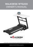
NOTE
Thank you for purchasing
the SPIRIT F7500 treadmill.
Please read carefully
through all the precautions
and instructions in this
manual before using this
equipment and keep this
manual for your future
reference.
F7500
TREADMILL
SERVICE CENTRE
NUMBER
For immediate help with
assembly or for additional
product information,
please call our service
center.
(DBN)
031 702 5784
(JHB)
011 907 1660
(CT)
021 934 0862
(PE)
041 487 0573
please have your model
name ready when you
call us.
MAXIMUM USER
WEIGHT
130kg
INSTRUCTION AND USER’S MANUAL
10155
CONTENTS
SAFETY PRECAUTIONS
page 1-2
PRE-ASSEMBLY CHECK LIST
page 3
PARTS LIST
page 4-6
HARDWARE PARTS LIST
page 7
EXPLODED DIAGRAM
page 8-12
ASSEMBLY INSTRUCTION
page 9-11
COMPUTER OPERATION INSTRUCTIONS
page 13-17
UNFOLDING/FOLDING AND TRANSPORT
page 18
BELT TRACKING ADJUSTMENT
page 19
TREADMILL LUBRICATION
page 20
EXERCISE INSTRUCTIONS
page 21-22
WARRANTY INFORMATION
page 23-25
SAFETY PRECAUTIONS
10155
IMPORTANT: THIS UNIT IS INTENDED FOR HOUSEHOLD USE ONLY
Your treadmill was designed and built for optimum safety. However, certain precautions apply
whenever you use your treadmill. Be sure to read the manual before assembly and operation.
Also, please note the following safety precautions:
DANGER: To reduce the risk of electric shock, always unplug the treadmill from the electrical
outlet immediately after using and before cleaning.
1.
Read OWNER OPERATING MANUAL and all accompanying literature and follow it carefully
before using your treadmill.
2. If dizziness, nausea, chest pains, or any other abnormal symptoms are experienced while
using this equipment, STOP the workout at once. CONSULT A PHYSICIAN IMMEDIATELY.
3. Never leave the treadmill unattended when plugged in. Unplug from the outlet when not in
use and before removing or replacing parts.
4. Never operate the treadmill if it has a damaged cord or plug, if it is not working properly, if it
has been dropped, damaged, or exposed to water.
5. Do not pull the treadmill by the power supply cord or use cord as a handle. Keep cord away
from heated surfaces and open flames.
6. Fitness equipment must always be installed and used on a flat surface. Do not use outdoors
or near water.
7. Do not insert any objects into any openings.
8. Keep children and pets away from this equipment at all times whilst exercising.
9. Handicapped individuals should have medical approval and close supervision when using
this treadmill.
10. Do not place hands or feet under the treadmill. Always keep hands and legs off of the
treadmill when others are using it.
11. Never turn on treadmill while standing on treadbelt. Always return the treadmill to slow speed
to ensure a safe dismount and low speed restart.
a. To disconnect, turn all controls to the off position, then remove plug from outlet.
b. Use the treadmill only for it is intended use as described in this manual.
c. Warm up 5 to 10 minutes before each workout and cool down 5 to 10 minutes afterward.
This allows your heart rate to gradually increase and decrease and will help prevent
straining muscles.
d. Never hold your breath while exercising. Breathing should remain at a normal rate in
conjunction with the level of exercise being performed.
e. Start your program slowly and very gradually increase your speed and distance.
f. Always wear suitable clothing and footwear while exercising. Do not wear loose fitting
clothing that could become entangled with the moving parts of your treadmill.
g. Do not walk or jog barefoot, in stocking feet or loose fitting shoes or slippers.
page-1
SAFETY PRECAUTIONS
10155
h. Care must be taken when lifting or moving the equipment, so as not to injure your back.
Always use proper lifting techniques.
12. If the supply cord is damaged, it must be replaced by the manufacturer, its service agent or
similarly qualified persons in order to avoid a hazard.
13. The treadmill is not to be used by children or persons with reduced physical, sensory or
mental capabilities, or lack of experience and knowledge, unless they have been given
supervision or instruction
14. Children being supervised should not to play with the treadmill.
WARNING
Before beginning any exercise program consult your physician. This is especially important for
individuals over the age of 35 or persons with pre-existing health problems. Read all instructions
before using any fitness equipment. We assume no responsibility from personal injury or property
damage sustained by or through the use of this product.
page-2
10155
PRE ASSEMBLY CHECK LIST
SPECIFICATIONS
• Drive Motor: 2.5 hp
• Speed Range: 1.0 – 16 kmph
• Running Surface: 510 x 1400 m/m
• Incline Level: 0-15 levels
• Folding Design: Yes
Getting started:
Power the treadmill on by plugging it into an appropriate wall outlet, then turn on the power
switch located at the front of the treadmill below the motor hood. Ensure that the safety key is
installed, as the treadmill will not power on without it.
When the power is turned on, a message will scroll across the dot matrix showing the current
Console
Safety Key
Incline Adjustment Switch
Speed Adjustment Switch
Handgrip Tube
Handpulse
Handrail
Running Belt
Main Frame
Wheel
page-3
10155
PARTS LIST
No.
Description
Q’ty
No.
10155-01
Main Frame
1
10155-32
Top Frame Cover
1
10155-02
Frame Base
1
10155-34
Motor
1
10155-03
Incline Bracket
1
10155-35
Incline Motor
1
10155-04
Right Handrail
1
10155-36
Controller ( external connection transformer)
1
10155-05
Left Handrail
1
10155-37
Speed Cable (Upper 800mm)
1
10155-06
Console Support
1
10155-38
Incline Cable (Upper 800mm)
1
10155-07
Deck Cross Brace
1
10155-39
Handpulse Assembly
2
10155-08
Outer Slide
1
10155-39-2
Handpulse Wire, Coiled (650mm)
1
10155-09
Inner Slide
1
10155-39-3
Handpulse Assembly Top
2
10155-10
Link
1
10155-39-4
Handpulse Assembly Bottom
2
10155-11
Link Shaft
1
10155-39-5
Handpulse End Cap
2
10155-12
Shaft Bushing
2
10155-40
1000 mlm Sensor W/Cable
1
10155-13
Fastening Bracket
2
10155-41
Breaker
1
10155-14
Clevis Pin
1
10155-42
Power Socket
1
10155-15
Fastening Bushing
1
10155-43
On/Off Switch
1
10155-16
Dual Rota-Spring
1
10155-44
Power Cord
1
10155-17
Release Lever
1
10155-45
Connecting Wires (Black 100mm)
2
10155-18
ChenChin Rota-Spring
1
10155-46
Connecting Wires (White 150mm)
1
10155-19
Cylinder
1
10155-47
Connecting Wires (Black 100mm)
1
10155-20
Drive Belt
1
10155-48
Computer Cable (Upper 800mm)
1
10155-21
Front Roller W/Pulley
1
10155-49
Computer Cable (Lower 1150mm)
1
10155-22
Rear Roller
1
10155-50
Computer Cable (Middle 1100mm)
1
10155-23
Running Deck
1
10155-51
Sensor Rack
1
10155-24
Running Belt
1
10155-52
Console Assembly
1
10155-25
Handle Bar Axle Inner Cover
2
10155-52-1
Top Console Cover
1
10155-27
Steel Rope Drawspring
1
10155-52-2
Bottom Console Cover
1
10155-28
Wire Clamp
1
10155-52-5
Beverage Holder (L)
1
10155-29
Wire Tie Mount
6
10155-52-6
Beverage Holder (R)
1
10155-30
Bottom Frame Cover
1
10155-52-14
Front Console Cover (Top)
1
10155-31
Steel Rope
1
10155-52-15
Front Console Cover (Bottom)
1
page-4
Description
Q’ty
10155
PARTS LIST
No.
Description
Q’ty
No.
Description
Q’ty
10155-52-16
Safety Switch Module w/Cable (300mm)
1
10155-69
Rear Adjustment Base (R)
1
10155-52-17
Fan
1
10155-70
Motor Cover Anchor
5
10155-52-18
Deflector Fan Grill
2
10155-71
Nylon Washer (ø10 x ø24 x 3T)
2
10155-52-19
Fan Grill Anchor
4
10155-72
Nylon Washer (B ø50 x ø13 x 3T)
4
10155-52-20
Speaker w/Cable (700mm)
1
10155-73
Foot Pad
2
10155-52-21
Speaker w/Cable (250mm)
I
10155-74
Motor Bracket
1
10155-52-22
Amplifier
1
10155-75
Ellipse Safety Key (800mm)
1
10155-52-25
Receiver, HR Assembly
1
10155-76
Belt Guide
2
10155-52-27
Speaker Iron Net (L)
1
10155-77
Wheel Sleeve
2
10155-52-28
Speaker Iron Net (R)
1
10155-78
Magnet
2
10155-52-30
Badge
1
10155-80
Carriage Bolt (1/2” x 1-1/4”)
2
10155-52-31
Power Cord of Amplifier (40cm)
1
10155-81
Hex Head Bolt (1/2” x l”)
2
10155-52-32
Sheet Metal Screw (3 x 10mm)
2
10155-82
Socket Head Cap Bolt (Alloy Steel 3/8” x 4-1/2”)
1
10155-52-33
Console Ground Wire (400mm)
1
10155-83
Hex Head Bolt (3/8” x 3-3/4”)
1
10155-53
Top Motor Cover
1
10155-84
Hex Head Bolt (3/8” x 1-1/2”)
1
10155-54
Speed Adjustment Switch w/Cable (300mm)
1
10155-85
Hex Head Bolt (3/8” x 3/4”)
4
10155-55
Incline Adjustment Switch W/Cable (300mm)
1
10155-86
Flat Head Socket Bolt (3/8” x 2” )
2
10155-56
Cushion
6
10155-87
Button Head Socket Bolt (5/16” x I” )
2
10155-57
Wheel (A)
2
10155-88
Button Head Socket Bolt (5/16” x 2-3/4”)
2
10155-58
Wheel (B)
2
10155-89
Hex Head Bolt (M8 x 60mm)
1
10155-59
Square End Cap (30 x 60mm)
2
10155-90
Socket Head Cap Bolt (M8 x 80mm)
2
10155-60
Foot Rail (300mm)
2
10155-91
Flat Head Countersink Bolt (M8 x 80mm)
2
10155-61
Foot Rail (615mm)
2
10155-92
Flat Head Countersink Bolt (M8 x 25mm)
6
10155-62
Frame Base Cap (L)
1
10155-93
Phillips Head Screw (M3 x 10mm)
1
10155-63
Frame Base Cap (R)
1
10155-94
Phillips Head Screw (M5 x 20mm)
1
10155-64
Left Connecting Cap (Top)
1
10155-95
Hex Head Bolt (M8 x 12mm)
2
10155-65
Left Connecting Cap (Bottom)
1
10155-96
Button Head Socket Bolt (5/16” x 42 rnm)
1
10155-66
Right Connecting Cap (Top)
1
10155-97
Nyloc Nut (M5)
1
10155-67
Right Connecting Cap (Bottom)
1
10155-98
Nyloc Nut (1/2”)
4
10155-68
Rear Adjustment Base (L)
1
10155-99
Nyloc Nut (3/8”)
4
page-5
10155
PARTS LIST
No.
Description
Q’ty
No.
Description
Q’ty
10155-100
Nyloc Nut (5/16”)
3
10155-130
Button Head Socket Bolt (5/16” x 1/2”)
8
10155-101
Nyloc Nut (M8)
1
10155-131
Combination M5 Allen Wrench &
Phillips Head Screw Driver
1
10155-102
Nyloc Nut (3/8”)
3
10155-132
Allen Wrench (M6)
1
10155-103
Nut (M3)
1
10155-133
Controller Back Plate
1
10155-104
Flat Washer (ø35 x ø5/16” x 1.5T)
2
10155-134
Lubricant
1
10155-105
Flat Washer (ø25 x ø10 x 1.5T)
4
10155-136
Ellipse End Cap
2
10155-161
Phillips Head Screw (M5 x 10mm)
4
10155-137
Sheet Metal Screw (3.5 x 32mm)
8
10155-162
Split Washer (M5 x 1.5T)
4
10155-139
Button Head Socket Bolt (3/8” x 1-3/4”)
4
10155-106
Flat Washer (ø19 x ø10 x 1.5T)
4
10155-140
Phillips Head Screw (M5 x 10mm)
8
10155-107
Flat Washer (ø5 x ø10 x 1.0T)
2
10155-141
Left Handgrip Side Cap (L)
1
10155-108
Flat Washer (ø5/16” x ø18 x 1.5T)
1
10155-142
Left Handgrip Side Cap (R)
1
10155-109
Flat Washer (ø5 x ø12 x 1.0T)
1
10155-143
Right Handgrip Side Cap (L)
1
10155-110
Flat Washer (ø1/4” x 19 x 1.5T)
2
10155-144
Right Handgrip Side Cap (R)
1
10155-111
Concave Washer (ø6.5 x ø25 x 1.5T)
8
10155-145
Cushion Spacer (L)
1
10155-112
Split Washer (M8)
2
10155-146
Cushion Spacer (R)
1
10155-113
Split Washer (ø10)
8
10155-147
Top Motor Cover Plate
1
10155-114
Split Washer (M3)
1
10155-148
Pedal Cover (Top)
2
10155-115
Star Washer (M5)
4
10155-149
Pedal Cover (Bottom)
16
10155-116
Sheet Metal Screw (4 x 12mm)
20
10155-150
Chest Strap
1
10155-117
Tapping Screw (5 x 16mm)
46
10155-151
Chest Strap (1000mm)
1
10155-118
Tapping Screw (5 x 19mm)
1
10155-152
Bolt Cap (13mm)
2
10155-119
Sheet Metal Screw (3.5 x 12mm)
35
10155-153
Audio Cable (400mm)
1
10155-120
Tapping Screw (5 x 16mm)
13
10155-154
Plastic Washer
4
10155-121
Flat Washer (ø13 x ø32 x 2.5T)
2
10155-156
Drink Bottle
1
10155-124
Tapping Screw (3 x 12mm)
4
10155-157
Sheet Metal Screw (3.5 x 18mm)
6
10155-125
Sheet Metal Screw (4 x 50mm)
2
10155-158
Filter
1
10155-126
Tapping Screw (3.5 x 16mm)
6
10155-159
Choke
1
10155-127
Sheet Metal Screw (3 x 10mm)
2
10155-160
Connecting Cable of Motor (400mm)
1
10155-128
Speed Nut Clip (M5)
6
10155-161
Phillips Head Screw (M5 x 10mm)
4
10155-129
Sheet Metal Screw (3 x 8mm)
6
10155-162
Split Washer (M5 x 1.5T)
4
page-6
10155
HARDWARE PARTS LIST
No.
Description
10155-75
Q’ty
No.
1pc
10155-131
4pcs
Sheet Metal Screw (3.5 x
12mm)
1pc
10155-132
Split Washer (ø10)
10155-119
Q’ty
Combination M5 Allen Wrench & Phillips
Head Screw Driver
Safety Key
10155-113
Description
1pc
Allen Wrench (M6)
4pcs
10155-134
1pc
Lubricant
6pcs
10155-120
10155-139
Tapping Screw (5 x 16mm)
Button Head Socket Bolt
(3/8” x 1-3/4”)
6pcs
10155-128
4pcs
10155-140
8pcs
Phillips Head Screw (M5 x 10 mm)
Speed Nut Clip (M5)
8pcs
10155-130
Button Head Socket Bolt
(5/16” x 1/2”)
Above described parts are all the parts you need to assemble this machine. Before you start to
assemble, please check the hardware packing to make sure they are included.
page-7
page-8
52-30
119
119 119 119
52-2
119 119
119
117
119
65
119
140
119
142
113
141
64
52-27
137
139
52-17
52-22
52-1
140
52-19
125
129
20
160
136
52-5
55
154
40
117
25
75
119
119
34
126
59
161
162
110
113
105
124
117
124
162
161
39-4
120
66
113
118
117
39-3
39-5
39-4
52-32
140
143
150
67
119
117
52-15 52-16
39-3
152
154
119
52-6
52-33
70
117
81
102
99
84
56 115
56
70
117
106
56
161
162
115
133
129
139
50
144
156
126
29
117
74 115
117 36
112 161
59
127 162
42
117
70
43
70
95 117
70 41
115
85
29
29
44
112
126
39-2
129
39-5
113
105
152
52-14
37
52-25
52-17 52-28
52-18
52-31 52-18 52-19
52-19 137
56
1
71
35
82
29
45
56
47
46
78
45
78
21
136
54
7
140
125
126
81
119
89
101
120
73
56
73
111
90
92 116
111 116
25
153
120
68
22
90
94
117
116
76
92
111
69
117
96
18
108 17
100
109
116
92
116
116
120
147
116
111
91
97
92
116
111
92 116
111 116
116
120
111
91
53
120
131
60
145
157
24
23
116
132
111
149
92
116
60
116
134
116
148
116
157
61
61
148
146
116
149
116
EXPLODED DIAGRAM
10155
10155
ASSEMBLY INSTRUCTION
STEP 1
Remove the treadmill from the carton and lay it on smooth, level ground.
STEP 2
• Install the 6pcs of Speed Nut Clips (128) on the Frame Base left and right side.
• Install the Frame Base Cap (62 & 63) through the Upright tubes (4 & 5), and connect the
Computer Cable (Lower 49) to the Computer Cable (Middle 50).
62
5
63
4
50
49
page-9
ASSEMBLY INSTRUCTION
10155
STEP 3
• Install the upright tubes (4 & 5) into the Frame Base (2) with the 8pcs of 5/16”x1/2”
Button Head Socket Bolts (130) using the Combination M5 Allen Wrench & Phillips Head Screw
Driver.
STEP 4
• Install the Frame Base Caps (61 & 62) on the Frame Base (2) with the 6pcs of 5x16mm
Tapping Screws (120) using the Combination M5 Allen Wrench & Phillips Head Screw Driver
(131).
page-10
10155
ASSEMBLY INSTRUCTION
STEP 5
• Connect the Speed Adjustment Switch Cable (#54) to the Speed Cable, Upper (#37).
• Connect the Incline Adjustment Switch Cable (#55) to the Incline Cable, Upper (#38).
• Connect the Computer Cable, Middle (#50) and Computer Cable, Upper (#48).
37 48
54
50
38
55
STEP 6
• Install the Console Assembly (#52) into the upright tubes (#4 & #5) with the 4pcs of 3/8”x1-3/4”
Button Head Socket Bolts (#139) and 4pcs of 10mm Split Washers (#113) using the M6 Allen
Wrench (#132).
52
113
132
113
139
139
5
4
page-11
10155
ASSEMBLY INSTRUCTION
STEP 7
• Install the Left Handgrip Side Cap and Right Handgrip Side Cap to cover the top of the upright
tubes (#4 & #5) and Console Assembly Support tubes, with the 8pcs of M5x10mm Phillips
Head Screws (#140) and 4pcs of 3.5x12mm Sheet Metal Screws (#119) using the Combination
M5 Allen Wrench & Phillips Head Screw Driver (#131).
119
140
131
119
140
140
140
Note: Please tighten all screws after all components have been assembled.
page-12
10155
COMPUTER OPERATION INSTRUCTIONS
When the power is turned on, a message will scroll across the dot matrix showing the current
software version. Then the Time and Distance windows will display Odometer readings for a
short time, Time window will show how many hours the treadmill has been in use and the
Distance window will show how many miles (or Kilometers if the treadmill is set to metric
readings) the treadmill has gone. The treadmill will then enter idle mode, which is the startingpoint
for operation. Getting started:
Power the treadmill on by plugging it into an appropriate wall outlet, then turn on the power
switch located at the front of the treadmill below the motor hood. Ensure that the safety key is
installed, as the treadmill will not power on without it.
page-13
10155
COMPUTER OPERATION INSTRUCTIONS
Quick-Start Operation:
STEP 1: Insert the Safety key to light up the display (if not already on).
STEP 2: Press the Start key to begin belt movement then adjust to the desired speed using the
Fast / Slow keys (console or handgrip). You may also use the rapid speed keys 2 through
12 to adjust the speed.
STEP 3: To slow tread-belt press and hold the Slow key (console or handgrip) to the desired
speed. You may also press the rapid speed adjust keys, 2 through 12.
STEP 4: To stop the tread-belt press Stop key or pull away Safety key.
Pause/Stop/Reset Feature:
STEP 1: When the treadmill is running the pause feature may be utilized by pressing the red Stop
key once. This will slowly decelerate the tread-belt to a stop. The incline will go to zero
percent. The Time, Distance and Calorie readings will hold while the unit is in the pause
mode. After 5 minutes the display will reset and return to the start up screen.
STEP 2: To resume your exercise, when in Pause mode, press the Start key. The speed and incline
will return to their previous settings.
• Pause is executed when the Stop button is pressed once. If the Stop key is pressed
a second time, the program will end and a workout summary will be displayed. If the
Stop button is pressed a third time, the console will return to the idle mode (start up)
screen. If the Stop button is held down for more than 3 seconds the console will reset.
Incline Feature:
• Incline may be adjusted anytime after belt movement.
• Press and hold the Adjust ▲ ▼ keys (console or handgrip) to achieve desired level of effort. You
may also choose a more rapid increase / decrease by selecting desired key, 2 through 12, on
left hand side of console (incline).
• The display will indicate incline position as adjustments are made.
Dot Matrix Center Display (Program Operation):
Twenty columns of dots (8 high) indicate each segment of a workout. The dots are only to show an
approximate level (speed/incline) of effort. They do not necessarily indicate a specific value - only
an approximate percent to compare levels of intensity. In operation the Speed / Incline dot matrix
window will build a profile “picture” as values are changed during a workout.
When the Speed indicator which is above dot matrix is lit the Dot matrix displays the Speed profile
and when the Incline indicator is lit the Dot Matrix displays the Incline profile.
You may change the Dot Matrix profile view which you desired by pressing the SELECT button.
After scrolling through the three profiles which include incline, speed and incline+ speed profile,
by pressing the SELECT button, the Dot matrix will automatically scroll through the three displays
showing each one for five seconds.
page-14
10155
COMPUTER OPERATION INSTRUCTIONS
0.4km (1/4 mile) Track:
The 0.4km (1/4 mile) track will be displayed around the dot matrix window. The flashing dot
indicates your progress. Once the 0.4km (1/4 mile) is complete this feature will begin again. The
amount of laps are accumulated in the laps window which is below PULSE.
Pulse Grip Feature:
The Pulse (Heart Rate) console window will display your current heart rate in beats per minute
during the workout. You must use both stainless steel sensors on the front cross bar to display
your pulse or the wireless chest strap. Pulse value displays anytime the upper display is receiving
a Pulse signal.
Calorie Display:
Displays the cumulative calories burned at any given time during your workout.
Note: This is only a rough guide used for comparison of different exercise sessions, which cannot
be used for medical purposes.
Optional: There is an Audio Input Jack on the front of the console and built-in speakers. You may
plug any low-level audio source signal into this port. Audio sources include MP3, Ipod, portable
radio, CD player or even a TV or computer audio signal. There is an audio patch cable included to
and also a headphone jack for private listening.
To Turn Treadmill Off (Blank out Display):
Two methods accomplish this: Use either one.
(1) Display will automatically turn off (blank out) after 10 minutes (no key operations) in Pause /
Stop mode.
(2) Remove safety key.
Programmable Features
Factory preset programs, 2 user defined programs, one Manual program (P0) and P1-P5
programs. Each preset program has a maximum speed level that is displayed when a desired
workout is chosen. The maximum speed that the particular program will achieve will be displayed
in the Speed window. Also included are two user programs (User 1 and User 2) for custom
workouts.
page-15
10155
COMPUTER OPERATION INSTRUCTIONS
To Select a Program:
STEP 1: Press the PROGRAM ▲ ▼ key to select desired program which include Manual (P0)
and P1-P5. Press enter to select the program. The display will prompt you through the
programming or you can just press Start to begin the program with default values.
STEP 2: If enter was pressed, the Time window will display with the default value of 20 minutes.
You may use any of the up/down, fast/slow keys to adjust the time. After adjusting, or to
accept the default value, press enter. (Note: You may press start at any time during the
programming to start the program.)
STEP 3: The Calorie window will now be displaying a value, which is your Body Weight. Entering
the correct body weight will affect the calorie count. Use the Up/Down keys, Fast/Slow to
adjust, then press enter.
A note about the Calorie display: No exercise machine can give you an exact calorie
count because there are too many factors which determine exact calorie burn for a
particular person. Even if someone is the exact same body weight, age and height, their
calorie burn may be very different than yours. The Calorie display is to be used as a
reference only to monitor improvement from workout to workout.
STEP 4: The Calorie window will display the preset top speed of the selected program. Use the
Up/Down, Fast/Slow keys to adjust, and then press enter. Each program has various
speed changes through out, this allows you to limit the highest speed the program can
reach.
User Programs:
STEP 1: Select User 1 or User 2 via the PROGRAM key then press Enter. Note that the dot matrix
display portion will have a single row of dots at the bottom (Unless there is a previously
stored program).
STEP 2: Note the Time window is flashing. Use the Adjust ▲ ▼ keys to adjust up from 10 minutes
(if desired). Press ENTER key. This is a must to continue even if time is not adjusted.
STEP 3: The Calorie window will now be blinking a bodyweight value. Enter your bodyweight and
press Enter.
STEP 4: The first column (segment) will now be blinking. Using the Fast / Slow or rapid keys,
adjust the speed level to your desired effort for the first segment then press enter. The
second column will now be blinking. Repeat the above process until all segments
have been programmed. The first column will be blinking again. This is for the incline
programming. Repeat the above process to program all segments for incline.
STEP 5: Press the Start button to begin the workout and also save the program to memory.
LUBE INDICATOR:
Every 180 hours or 1000km of use apply one half bottle of lubricant between running belt and
running board.
page-16
10155
COMPUTER OPERATION INSTRUCTIONS
ERROR MESSAGE:
1. LS: Treadmill doesn’t receive the speed signal for 8 seconds.
2. E1: Memory of console malfunction or CPU accessing problem.
3. E2: Incline position error.
Program
P1 SPEED PROGRAM
P1 INCLINE PROGRAM
P2 SPEED PROGRAM
P2 INCLINE PROGRAM
P3 SPEED PROGRAM
P3 INCLINE PROGRAM
P4 SPEED PROGRAM
P4 INCLINE PROGRAM
P5 SPEED PROGRAM
P5 INCLINE PROGRAM
page-17
10155
UNFOLDING/FOLDING AND TRANSPORT
Do not attempt to move the unit unless it is in the folded and locked position. Be sure the power
cord is secured to avoid possible damage. Use both handrails to maneuver the unit to the desired
position.
Unfoldong The Treadmill:
Apply slight forward pressure* on the treadmill running deck with one hand. Pull down on the
unlocking lever and slowly lower the running deck to the floor. The deck will lower unassisted
when it reaches about waist high. (As shown Figure 1.)
*At the rear roller area to relieve pressure on the locking system.
Folding The Treadmill:
Make certain the treadmill is at minimum incline. Lift the treadmill running deck until it is secured by
the locking telescoping tube assembly in center back of base.
(As shown Figure 2&3.)
Transport
The treadmill is equipped with four transport wheels which are engaged when the treadmill is
folded. After folding simply roll the treadmill away. (As shown Figure 4.)
page-18
BELT TRACKING ADJUSTMEANT
10155
If during use you notice that walking belt either shifts to the right or the left of center, first
remove “Safety Key” and unplug equipment from AC power source. Using M6 Allen wrench
provided, turn left rear roller adjustment as indicated below clockwise no more the 1/4” of a
turn. Remove M6 Allen wrench, insert “Safety Key” and insert AC power cord into AC outlet.
Turn on your treadmill and observe after running a few minutes to see if problem has been
corrected. This may take several adjustments, so repeat the above procedure.
page-19
TREADMILL LUBRICATION
10155
Your treadmill should require little maintenance other then periodically applying lubricant.
Lubricating under the running belt will ensure superior performance and extend its life expectancy.
HOW TO CHECK THE RUNNING BELT FOR PROPER LUBRICATION?
Lift one side of the running belt and feel the top surface of the deck.
If the surface is slick to the touch, then no further lubrication is required.
If the surface is dry to the touch, apply one packet of lubricant or half of the bottle of lubricant.
HOW TO APPLY LUBRICANT?
1. Lift one side of treadbelt.
2. Pour one half of the lubricant bottle under the center of the treadbelt on the top surface of the
deck.
3. Walk on the treadmill at a slow speed for 3 to 5 minutes to evenly distribute lubricant.
NOTE: DO NOT over lubricate treadmill. Any excess lubricant that comes out should be wiped off.
IMPORTANT: NEVER USE MORE THAN HALF THE BOTTLE OF LUBRICANT PER
APPLICATION LUBRICATION SCHEDULE.
1. It is best to lubricate your treadmill before you use it for the the first time.
2. If you do not lubricant your treadmill before you use it for the first time, you should lubricate it
after the first 25 hours of use (2-3 months ).
3. Every 180 hours or 1000km of use, apply half a bottle of lubricant.
page-20
EXERCISE INSTRUCTIONS
10155
Using your TREADMILL will provide you with several benefits. It will improve your physical fitness,
tone muscle and in conjunction with a calorie controlled diet, help you lose weight.
1. The Warm Up Phase
This stage helps get the blood flowing around the body and the muscles working properly. It will
also reduce the risk of cramp and muscle injury. It is advisable to do a few stretching exercises as
shown below. Each stretch should be held for approximately 30 seconds, do not force or jerk your
muscles into a stretch - if it hurts, STOP.
INNER THIGH
FORWARD BENDS
CALF / ACHILLES
SIDE BENDS
OUTER THIGH
2. The Exercise Phase
This is the stage where you put the effort in. After regular use, the muscles in your legs will become
more flexible. Work to your own pace but try to maintain a steady tempo throughout. The rate of
work should be sufficient to raise your heart beat into the target zone shown on the graph below.
This stage should last for a minimum of 12 minutes though most people start at about 15-20
minutes.
page-21
EXERCISE INSTRUCTIONS
10155
3. The Cool Down Phase
This stage is to let your Cardio-vascular System and muscles wind down. This is a repeat of the
warm up exercise, however reduce your tempo and continue for approximately 5 minutes. The
stretching exercises should now be repeated, again remembering not to force or jerk your muscles
into the stretch.
As you get fitter you may need to train longer and harder. It is advisable to train at least three times
a week, and if possible space your workouts evenly throughout the week.
MUSCLE TONING
To tone muscle while on your TREADMILL you will need to have the resistance set quite high.
This will put more strain on your leg muscles and may mean you cannot train for as long as you
would like. If you are also trying to improve your fitness you need to alter your training program.
You should train as normal during the warm up and cool down phases, but towards the end of
the exercise phase you should increase resistance making your legs work harder. You will have to
reduce your speed to keep your heart rate in the target zone.
WEIGHT LOSS
The important factor here is the amount of effort you put in. The harder and longer you work the
more calories you will burn. Effectively, this is the same as if you were training to improve your
fitness, the difference is the goal.
page-22
SPIRIT 1 YEAR LIMITED WARRANTY
10155
Masstores (Pty) Ltd (“the Supplier”) hereby provides a limited warranty to the original purchaser of
this product (“the Consumer”) that this product will be free of manufacturing defects in materials
and workmanship which under normal, personal, family or household use (commercial use
expressly excluded) manifest themselves within the following stipulated periods from the date of
purchase:
Exclusions
The warranty does not include and will not be construed to cover products damaged as a result of
disaster, misuse, commercial use, use not in accordance with the written instructions included with
the product, abuse, and/or any non-authorised modification of the product. It also does not cover
replacement of the light bulbs and other expendables. All demo models carry a 3 month warranty.
Waiver
The warranty provided herein and the obligations of the Supplier are in lieu of, and the Customer
waives, all other warranties, guarantees, conditions or liabilities, express or implied, arising by law
or otherwise, including without limitation, any obligation of the Supplier in respect of any injury,
loss or damage (direct, indirect or consequential) arising out of the use of, or inability to use, this
product and whether or not occasioned by the Supplier’s negligence or any act of omission on its
part.
CLAIMS UNDER 1 YEAR LIMITED WARRANTY
• Within 7 days of purchase:
The faulty product will be exchanged (provided that the product is in its original packaging with
all accessories).
• After 7 days but within 3 months of purchase:
The Supplier may in its sole discretion either replace or repair the product.
• After 3 months but within 1 year of purchase:
The Supplier may in its sole discretion either replace or repair the product. The following shall
not be covered:
TREADMILLS : Running Decks, Running Belts, and Rubber Arm covers
EXERCISE BIKES / SPINNERS : Pedals, Cranks, Seats and Rubber Arm covers
CROSS TRAINERS / ELLIPTICALS / STEPPERS : Foot Rests, Cranks, Shocks, and Rubber / Foam Arm Covers
HOME GYMS : Pulleys, Cables, Seats and Padding
TRAMPOLINES : Springs, Mats and Covers
ROWERS : Rowing Strap / Rope /Arms, Pulling Handle, Grip, Moveable Seat
VIBRATION TRAINERS : Platform / Rubber Arm Cover / Resistance Bands
Parts not mentioned in the above, are covered under warranty within the 1st year of purchase.
page-23
SPIRIT REPAIRS PROCEDURE
10155
1. Procedure for repairs
Should you experience any faults or breakdowns on your Spirit equipment, please adhere to
the following procedure to have the fault rectified speedily and professionally.
• Do not return the product to the store.
• Call the Service Centre to log the faulty product (under warranty or out of warranty).
• The operator or technical advisor will try to identify the fault and will book a service.
• The service team will take the faulty product back to the service centre.
• Once the item has been repaired it will be returned to the Consumer’s home on an agreed
date and time.
Note: Should you live in an outlying area, it may be necessary to return the product to the
store nearest to you. Our service operator will advise you of your repair procedure.
2. Cost of repairs
2.1. Under warranty
• Any items still under warranty will be repaired free of charge, as long as it complies with the
terms and conditions of the warranty (refer to “warranties” section of this manual).
• Any items that need to be repaired that are NOT covered in the warranty will be for the
Consumer’s expense. A quote for the repair/replacement of these items will be provided to
the Consumer for approval prior to repairs being conducted.
2.2. Out of warranty
• Any items that need to be repaired once the warranty has expired will be for the Consumer’s
expense, including call-out fees. A quote for the repair/replacement of these items will be
provided to the Consumer for approval prior to repairs being conducted.
page-24
PROOF OF PURCHASE
10155
Any claim in terms of the warranty must be supported by a proof of purchase or a warranty
number. Warranty numbers can be issued through contacting our Service Centre. If such proof is
not available, then not withstanding anything to the contrary herein, the service agent’s prevailing
charges for services / repairs including call-out and / or spares will be payable by the Consumer
upon collection or delivery of the repaired product.
The Consumer does not need to return the product to the store.
The Consumer shall phone the Service Centre and the Supplier’s authorized agent will collect and
repair the item at their premises.
During the warranty period the product may only be serviced and/or repaired by the Supplier’s duly
authorized agent(s).
Masstores (pty) Ltd
16 Peltier Drive, Sunninghill
Sandton, Johannesburg, South Africa
page-25