1
OPTICODEC
7200 / 7400 / PC Remote
Handbuch
OPTICODEC
Manual
7200/7400
Software V4.25/2007
PC
REMOTE
Software V1.24/2007
Table of Contents
The Codec Technology
7
OPTICODEC 7200 and 7400
Certification / Labelling
8
Description, Introduction and Installation 9
OC 7200 Front Panel / Keypad
Explanation of Keypad Symbols
OC 7200 and 7400 Rear Panel
Basic Connections
Audio Input, symmetrical
Audio Output, symmetrical
Digital In-/Output
(AES/EBU standard)
10
11
Digital In-/Output
(S/PDIF standard)
External Synchronisation
Serial, Synchronous Interface (X.21)
12
RS232/RS422, Serial, Asynchronous
Interface (Remote)
13
Alarm/Control Interface
RS232/RS422, Serial, Asynchronous
Interface (Ancillary)
Standardized Connector
to Ethernet
Standardized Connectors
to ISDN Network
U Connector
Power Supply
OPTICODEC PC Remote
Introduction
Connection to PC
14/15
16
17
18
Software Installation
Download of OC Remote Software
Program Configuration
19
Release of Additional Features
20
Software Info and Update
4
E
20/21
Update Process Interrupted
DSP Software
System Software
Hardware Configuration
Boot Software
22
Jumper Settings
Important Jumpers on the Main Board
Input Impendance
Switch over RS232/RS422
23
Data Input
Enter New Recipient
24
ISDN Connection
Edit Recipient
25
Audio Data Encoder
Algorithm, ISDN Sync, Bitrate
Samplingrate, Audio Mode
Audio Input, Userdata
26/27
G.722 with H.211 or SRT Sync
X.21 Mode, Codec Loop
28
Ethernet Connection
IP Connection
Point-to-Point, Transmit, Receive
29
Broadcast, Multicast,
Applications:
LAN, WAN,
Broadcast, Multicast
30/31
Tip
Saving Units ISDN/IP Directory
to your PC Harddisk
Edit Saved Directory
32
Loading ISDN/IP Directory to
a Unit
33
System Setup
Configuration of the connected
OPTICODEC in System Setup
TCP/IP Basics
Local IP Address
Subnet Mask
Default Gateway
OPTICODEC
34
Table of Contents
Dialing
TCP/IP Audio
Buffer Management
35
Quality of Service
Type, TOS,
Precedence and TOS Values
DiffServ, DiffServ Codepoints 36/37
Audio Data Encoder
37
Audio Port (TCP)
TCP/IP Remote Control
Name, Port
38
Autodetect
Accept Configuration
39
Dialing: Dial. Attempts, Dial. Delay
Redialing Attempts
PBX Prefix
Min. length for PBX Prefix
40
ISDN Configuration
ISDN Protocol
Accept Telephone Calls
Accept MPEG/G.722 Calls
MSN Check
41
ISDN Interface
Number Prefix for incoming calls
Local Numbers
SPID Numbers
I/O Levels
Misc
Alarm Signals
Level Range, Headroom
External Sync Input
Backlight
Automatic Connection Start
Backup Settings
X.21 Clock Monitoring
Saving Units System Setup to
your PC Harddisk
42
43
Loading System Setup
to a Unit
Default Configuration
Connect
Establishing a Con. w ISDN/IP Dir.
49
Establishing Connnection
Establishing a Con. w. DD Buttons
50
Automatic Connection Start
Coonection Monitoring
51
Currency Icon
Sync Icon
Ajust Audio Parameters
Adjust Audio Levels
52
Establishing a Con. w. mit X.21
Establishing a Con. w. Codec Loop
Call Acceptance with ISDN Sync AUTO
Establishing a Con. w. ISDN Sync AUTO
Terminating a Connection
53
OPTICODEC 7400
Front Panel / Keypad
Explanation of Keypad Symbols
Graphical Display Module
54/55
Data Input
Enter New Recipient
Connection Mode
56
ISDN Connection
ISDN Numbers
ISDN Sync
57
44
45
48
Audio Data Encoder
Shortname
Store & Exit
58
IP Connection
Point-to-Point, Transmit, Receive
IP Address
59
Broadcast
Multicast
Audio Data Encoder, Shortname
Store & Exit
60
46/47
48
OPTICODEC
E
5
Table of Contents
System Setup
Accept Configuration
Algorithm, ISDN Sync
Samplingrate
Audio Mode
Audio Input
Userdata
ISDN Configuration
ISDN Protocol
ISDN Interface
Local Numbers
SPID Numbers
Dialing: Dial. Attempts, Dial. Delay
Redialing Attempts
PBX Prefix
Min. length for PBX Prefix
Incoming Calls
Accept Telephone Calls
Accept MPEG/G.722 Calls
Test Called Number
ISDN Interface
Number Prefix for incoming calls
61
62
63
64
65
66
Subnet Mask
67
Default Getaway
Remote Control
Name
68
Port
Accept Configuration
Audio Data Decoder
Dialing
Quality of Service
69
E
Interfaces
External Sync Input
Alarm Signals
73
70
73/75
Automatic Connection Start
75
X.21 Clock Monitoring
76
Backlight
Base Configuration
Reset Configuration
Delete Database
77
Connect
Explanation of the Display Lettering
Establishing a Con, w. ISDN/IP Dir.
ISDN Connection Establishment
78
Ethernet Connection Establishment
Establishing a Con, w. Quick Dial
78
Establishing a Con, w. DD Buttons
Connection Monitoring
Currency Icon
80
Sync Icon
Establishing a Con. w. mit X.21
Establishing a Con. w. Codec Loop
Connect Menu
Terminating a Connection
81
Status Messages
Number Codes in Standby Mode
ISDN Error Codes
TOS, Precedence and TOS Values
DiffServ, DiffServ Codepoints
71
6
72
Backup Settings
Applications
TCP/IP Configuration
Local IP Address
Port
Auto Detect
Audio Transmission
Buffer Management
Audio Level
Level Range
Headroom
Adjust I/O Levels
82
83/84/85
Brief Lexicon
Ethernet Error Codes
86
Technical Specifications
87
Delivery Scope
88
OPTICODEC
The Codec Technology
The "ISO-MPEG Audio Layer 2 and Layer 3“ compression
procedures developed by the Fraunhofer Institute and the
Institut für Rundfunktechnik allow audio signals (even large
amounts of data) to be reduced in real time and transferred
without any subjective loss of quality. The digitised signals
received in this form are compressed (encoded) to save
on transmission bandwidth, time and cost.
CODEC is a word coined from the verbs "enCOde“ and
"DECode“ and stands for a new data transfer technology
via ISDN or satellite.
The principle of codec technology for audio data reduction
is based on the frequency-dependent sensitivity of the human ear. According to its objective auditory properties and
subjective hearing habits, the ear ignores certain sounds
and concentrates on the most essential ones: the message.
This contrasts with purely electronic techniques which hear
everything, even the non-essential noise.
The codec technology takes advantage of the difference
between the ear and electronic measuring device when
transferring data. By masking all meaningless noise, even
the minutest, a reduction ratio is achieved, which is necessary to transport large amounts of data in real time via
ISDN, for example. The data is instantly decompressed and
subjected to A/B comparison and then the ear at the other
end of the line hears only what it is intended to hear –
no more and no less.
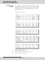
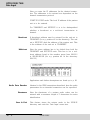
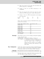
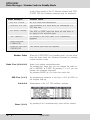
Some typical examples of data reduction rates achieved
with ISO-MPEG1 can be seen in the following table:
Algorithm
in Layer 1
Bitrate
(kbps)
384
Audio
mode
Stereo
Reductions
ratio
1:4
in Layer 2
192...256
Stereo
1:6...1:8
in Layer 3
112...128
Stereo
1:10...1:12
OPTICODEC
E
7
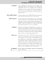
OPTICODEC 7200 and 7400
Certification / Labelling
The OPTICODEC units hereafter complies to the following
regulations and standards:
EN 60950/VDE 0805/IEC 950: Protection Class 1.
VBG4, Part 5 paragraph 4: Regulations for the prevention
of accidents “Electrical Systems and Materials”.
EC directives: EMV 89/336/EWG and “low voltage regulation” 73/23/EWG.
FCC Rules, Part 68 Subpart D:
FCC/Part 68 registration number US: OBDYNAN42059.
Industry Canada registration number IC: 4265A-001.
EMC directives:
DIN EN 55103-1 (June 97) - interference radiation, ambiance
E1 and DIN EN 55103-2 (June 97) - resistance to jamming,
ambiance E5, intensity degree 4 (ITU/R recommendation
500-4).
EN 50419:2005 Marking of Electrical and Electronic Equipment accordance with Directive 2002/96/EC (WEEE).
For recycling the OPTICODEC please refer to your responsible OPTICODEC distributor.
Note on
EMC Measures
8
E
According to the requirements of the EMC directive, the
regulations for electromagnetic compatibility, it is necessary
that the following measures are observed when using/manufacturing the connection cables:
For all connections shielded cables should be used
(with respect to the audio cables the well-known EMT
211 has proven its worth).
The shields should be soldered to the GND connections
and additionally to the connector shell directly.
For 3-pole audio sockets/plugs (type XLR) the respective
counter sockets/plugs manufactured by NEUTRIK should
be used.
Pin 4 (housing) is to be connected to pin 1 ground.
OPTICODEC
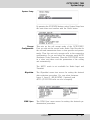
OPTICODEC 7200 and 7400
Description, Introduction and Installation
Description
The OPTICODEC 7200 and 7400 are fully duplex audio
codecs with ISDN and X.21 interfaces as a standard. The
OPTICODEC 7400 is also equipped with an Ethernet
100Base-Tx interface for the remote control and distribution
of audio data over networks such as Intranet, ATM etc.
TCP for Point-to-Point connections, UDP for Broadcast and
Multicast modes.
Ethernet/ISDN Cabling
Correct operation of the OPTICODEC is only guaranteed
when using the delivered RJ45 Typ CAT5 cables.
ISDN Connection
Correct operation of the OPTICODEC is only ensured when
the unit is connected to an approved Telecom access. When
operating the unit on other telephone networks (private
exchange), several adjustments are necessary. Please see
chapter ‘System Setup’. Adaptation to certain networks other
than herewith specified can not be guaranteed.
Installation
The units are designed for installation into 19” racks. Installation with additional mounting rails is recommended
because of the depth of the units. The OPTICODECs do not
have internal fans and do not necessarily require additional
ventilators even when built into racks. A minimum distance
does not have to be kept within installed units.
Please note
This manual is for the use of OPTICODEC owners and their
staff only. The information in the manual, including all texts
and drawings, is to be treated as confidential and may
not be passed on to third parties, reproduced, translated
or multiplied in any form whatsoever. Hereby the right to
register utility models or patent applications is reserved
explicitly. In the case of violation or non-compliance resulting in consequential losses, ORBAN Europe GmbH may be
entitled to claim damages according to the German BGB,
HGB as well as Competition Law and Patents Act.
Comments
In this manual the simplified denotation ‘OPTICODEC‘
refers to both units.
OPTICODEC
E
9
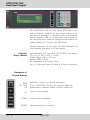
OPTICODEC 7200
Front Panel / Keypad
Explanation of
Keypad Symbols
SYNC OK
Display of the decoder sync flag. If this LED lightens, the
decoder receives correct data from the partner unit.
MODUS
X.21
Shows an X.21 connection.
ISDN Shows an ISDN connection.
For ‘codec loop’ none of the above displays are active.
STATUS
CLOCK ERROR
Only for an X.21 connection. Shows that there is either no
clock at the X.21 connection or a clock with the wrong
frequency.
CON
Only for ISDN connections. Shows that at least one B-channel is connected to the partner unit.
OK
For X.21: connection established.
For ISDN: ISDN connection synchronized.
The connection is fully established as soon as the Sync
‘OK’ LED lightens additionally.
REJ
10
E
Only for ISDN: connection could not be established.
HANG UP
By pressing this key a connection can be disconnected. It
has no function, if no connection had been established. If
the key is pressed for the first time, the STANDBY LED
flashes. The ‘Hang Up’ key has to be pressed again within
10 seconds to disconnect the line.
STANDBY
Shows that the unit can be called or can establish a connection itself.
OPTICODEC
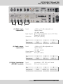
OPTICODEC 7200 and 7400
Rear Panel / Basic Connections
1
2
(1) Audio input,
symmetrical
3
Level:
Input Imped.:
Connector:
-4 dBu to.+21 dBu adjustable via
‘System Setup’
(+12 dBu preset)
10 kOhm (switchable over to 600 Ohm,
jumper JP 800/801
XLR jack (female)
Pin
Assignment
(2) Audio output,
symmetrical
2
3
GND
IN (+)
IN (-)
Level:
-4 dBu to.+21 dBu adjustable via
‘System Setup’
(+12 dBu preset)
Output Imped.: < 50 Ohm
Connector:
XLR jack (male)
Pin
Assignment
(3) Digital input/output
(AES/EBU standard)
1
Level:
Connector:
1
2
3
GND
OUT (+)
OUT (-)
according to IEC 958, prof. format
XLR jack (female/male)
Pin
Assignment
OPTICODEC
1
2
3
GND
IN/OUT (a)
IN/OUT (b)
E
11
OPTICODEC 7200 and 7400
Rear Panel / Basic Connections
4
(4) Digital Input/Output
(S/PDlF standard)
5
Connector:
6
7
RCA (female/female)
Pin
Center Pin
Ring
IN
GND
Assignment
(5) External
synchronisation
adjustable via ‘System Setup’
Connector: BNC jack (male/male)
Signal level: TTL
Pin
Center Pin
Ring
IN
GND
Assignment
(6) Serial Synchronous
Connection
(X.21)
for the transmission of
data transmission unit,
MODEM.
Transmission Rate:
Connector:
Pin
Assignment
Pin
Assignment
Function*
E
coded audio data to an external
e.g. terminal adapter or satellite
8 to 384 kbps
15-pole Sub-D
1
2
3
4
5
NC
Tx
(a)
O
CTR
(a)
O
Rx
(a)
I
IND
(a)
I
6
7
8
9
10
CLK
(a)
I
NC
GND
Tx
(b)
O
CTR
(b)
O
Function*
12
8
OPTICODEC
OPTICODEC 7200 and 7400
Rear Panel / Basic Connections
Pin
11
12
13
14
15
Assignment
Rx
IND
(b)
I
CLK
(b)
I
NC
NC
Function*
I
O=output
* related to OPTICODEC
(7) RS232/RS422
Serial Asynchronous
Interface
(Remote)
to control the OPTICODEC using an external PC
(pls. see also chapter ‘PC Connection’, page 18).
Switch over from RS232 to RS422: Jumper J3 to 1+2
(pls. see also chapter ‘Jumper Settings’, page 23).
Format RS232/RS422:
9600 baud
8 data bits
1 stop bit
no parity
Connector:
9-pin Sub-D
Pin
Assignment
RS232
RS422
Function*
1
Tx+
Pin
Assignment
RS232
RS422
Function*
6
Tx-
7
NC
8
NC
9
Rx+
O
I
O
I
O
2
3
RC_Tx RC_Rx
O
4
Rx-
I
* related to OPTICODEC
=not to be used!
=assigned
Warning
I=input
5
GND
I
O=Output I=Input
For RS232 internal signals are assigned to pins 2, 3 and
5, for RS422 to pins 1, 4, 5, 6 and 9!
A fully assigned 1:1 cable to the PC might result in the
damage of the PC and/or OPTICODEC!
Please use only cables as described above.
OPTICODEC
E
13
OPTICODEC 7200 and 7400
Rear Panel / Basic Connections
(8) Alarm/Control
Interface
The switching commands of the OPTICODEC input are
transmitted and made available as open collector signals
at the partner unit. The inputs and outputs (same as GND
connections 13, 25) are electrically isolated via an optoelectronic coupler.
Connector: 25-pin Sub-D
Pin
Assignment
Function*
Pin
Assignment
Function*
Pin
Assignment
Function*
1
NC
2
NC
3
NC
4
5
IN8
GND
Red-Light
IN
6
7
8
IN7
IN6
IN5
Reset (Index) FF
11
12
IN2
IN1
Record Play
9
IN4
Rew
13
IN GND
**
14
NC
Pin
16
17
18
Assignment
VCC OUT8
OUT7
Function*
+5V Red-Light Reset
System Setup***
DIS
Pin
Assignment
Function*
*
**
***
****
14
E
21
22
23
OUT4 OUT3 OUT2
Rew Stop Record
15
NC
19
20
OUT6 OUT5
(Index) FF
CON
24
OUT1
Play
related to OPTICODEC
common earth for all inputs
pls. see 'Alarm Signals' (pages 44 and 73)
common earth for all outputs
OPTICODEC
10
IN3
Stop
25
O.GND
****
OPTICODEC 7200 and 7400
Rear Panel / Basic Connections
Input Wiring
Imax.:
10 mA
internal
Output Wiring
Imax.:
Umax.: 25 V
external
10 mA
or
extrenal
internal
external
Please note
The recommended functions of the inputs and outputs
correspond to the way these are assigned by OPTICODEC
users. These assignments should be taken over to avoid any
problems in remote controlling externally connected units
during transmissions between different OPTICODEC units.
Warning
When manufacturing a connection cable for the interfaces
Alarm Control Interface and Ancillary, the respective connector shells (width: 15 mm) have to be used:
* for e. g.: Farnell Electronic
Components GmbH,
D-82041 Deisenhofen
Fax: +49 / 89 613 5901
www.farnell.com
Type/Pole
9-pole
25-pole
OPTICODEC
Sub-D Shell
DTZK-9-K
DTZK-25-K
Order No*
463-012
463-036
E
15
OPTICODEC 7200 and 7400
Rear Panel / Basic Connections
9
(9) RS232/RS422
Serial Asynchronous
Interface
10
11
12
13
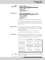
to transmit user data via OPTICODEC.
Format:
0 ... 9600 baud (pls. see table)
8 data bits
1 stop bit
no parity
Table of implemented ancillary data starting from software
V4.10
Data rate:
(kbps)
Layer 2:
(baud)
Layer 3:
(baud)
Note
8
16
16
E
32
48
56
64
128
0 1200 1200 2400 2400 2400 4800 4800
0 1200 1200 2400 2400 4800 4800 9600
If the software version of one or both of the OPTICODECs
is
V4.10, then a baud of 1200 is always utilised.
If the software version of both units
V4.10, the
OPTICODECs are automatically set to the lowest default
ancillary data rate.
Connector:
Warning
24
9-pin Sub-D
Pin
Assignment
Function*
1
NC
2
R_Tx
O
3
R_Rx
I
4
NC
Pin
Assignment
Function*
6
NC
7
RTS
8
CTS
9
NC
Internal signals are assigned to pins 7 and 8.
These pins should not be connected!
OPTICODEC
5
GND
OPTICODEC 7200 and 7400
Rear Panel / Basic Connections
(10) Standardized
Connector
to Ethernet
Transmission Rate:
Connector:
10 Mbit/s
RJ45
Pin
1
Assignment TD+
(11) Standardized
Connectors
to ISDN Network
Transmission Rate:
Connector:
Pin
Assignment
2
TD-
3
RD+
6
RD-
2 x B + D channel per S0
RJ45 for S0 connections
3
T+
4
R+
5
R-
6
T-
and RJ11 for U connection
(USA and Canada networks only)
(12) U Connector
7400
Pin
Assignment
1
2
3
U
4
U
5
6
1...
3
4
U
5
U
6...
8
7200 (optionally)
Pin
Assignment
Note
(13) Power Supply
The ISDN interfaces have to be used in incremental
sequence.
100-240 V AC, 50-60 Hz, 0.375-0.20 A, max. 25 VA
The OPTICODEC has a switching power supply unit.
Therefore a voltage selector switch is not necessary.
Power Supply Fuse:
Connection
3.15 A in power supply
Type Schurter MXT 315.
3pole socket
OPTICODEC
E
17
/04)#/$%#0#2EMOTE
)NTRODUCTION
Description
The OC PC Remote software is a 32-bit version for Microsoft
Windows 98/2k/ME/XP for the remote control of the OPTICODEC over the RS232 interface using a PC. It covers the
same adjustment parameters as the OPTICODEC itself.
Note
To avoid any misunderstanding, the ‘OPTICODEC PC
Remote’ is referred to on the following pages as ‘OC Remote’
or ‘OC Remote software’.
Information
The licensee may not copy the software or the included
original documentation or own any such copies. Furthermore, the licensee may not change, adapt, translate, duplicate,
loan, lease or in any other form supply the availability of
the software or service instructions as a whole or any part
thereof. It is strictly forbidden to reengineer or disassemble
the software, or in any other way and means attempt to trace
the source code. Due to the further development for product
improvement of the present series units and alterations of
certain industrial parts, it cannot be avoided that some parts
might not be fully compatible. Different component modifications can lead to different configuration options. Deviating
program sections in the software are therefore possible.
All technical information may be subject to change without
notice.
Connection
to PC
The connection between the PC and your OPTICODEC
occurs via a serial 9-pole or a 25-pole cable (KB003 male/
female).
Connected to PC
Connected to OPTICODEC
System requirements: Microsoft Windows
98/2k/ME/XP and a free PC serial interface.
%
/04)#/$%#
OPTICODEC PC Remote
Software Installation
Download of the
OC Remote Software
Start the setup program of the current application from the
Internet or from the delivered data medium with a doubleclick on the setup icon. Follow the installation instructions
on the PC screen.
With double click on the icon you start the application.
After a short initializing sequence the basic configuration
menu of the connected OPTICODEC appears.
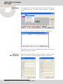
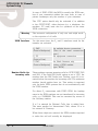
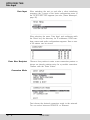
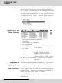
Program Configuration
A mouse click on the 'Program' menu opens a pulldown
menu.
This configuration is only necessary if ‘TIMEOUT!’ is
displayed and not ‘STANDBY’. With the menu item ‘Program
Configuration’ you can adapt the PC serial interface and
adjust the display colors.
A safety query to appear before a connection is
disconnected can be set up by activating the ‘Confirm
disconnect’ check box.
Via 'Default Input' you can select the audio input by using of
the Direct Dial Buttons. You can choose between: Analog,
AES/EBU and S/PDIF.
Confirm yor settings with ‘OK’.
OPTICODEC
E
19
/04)#/$%#0#2EMOTE
3OFTWARE)NFO
Release of
Additional Features
The menu item 'Enter key codes' is used for release of
additional features (e.g. the 4SB ADPCM algorithm). The
release is dependent on the unit model and its serial number. Each unit receives a unique key code. This function
is only active in the standby mode.
About OC Remote
A window is displayed over the next menu item called
“About OC Remote” where you will find information on the
version number, creation date and manufacturer of the
OPTICODEC PC Remote software.
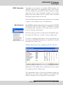
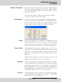
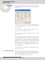
Info
This function is found on the 'Unit/Info' pulldown menu
and serves to display the latest software versions of the
connected OPTICODEC unit.
All software parts with their corresponding versions are displayed.
You can also interrogate the serial
number of your OPTICODEC.
%
/04)#/$%#
OPTICODEC PC Remote
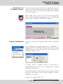
Software Update
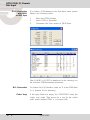
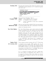
Software Update
This function is found on the 'Unit/SoftwareUpdate' pulldown menu.
If necessary, please store the device-specific *.BIN file on
your local hard drive under Program Files/Orban/OpticodecRemote/Updates. The program automatically recognizes
the connected OPTICODEC and which software parts are
to be updated.
A dialogbox accompanies you throughout the update and
informs you about the current process.
The OPTICODEC 7400 shows the update process in the
display.
Warning
Do not switch off your PC or OPTICODEC during the
update process.
Damaged or incompletely loaded software always causes
an error message. After a failed update, you may repeat
the update process.
OPTICODEC
E
21
OPTICODEC
Software Update
OPTICODEC
Update Interrupted
If the software update was interrupted, for e.g. due to a user
or computer error, please observe the following:
Switch the unit OFF and ON again. In most cases the unit
displays an error message about that part of the software
which had not been loaded completely and a reload is
requested.
DSP Software
In case of the DSP software an error message might not be
displayed after switching the unit on and the main menu
is displayed as normal. The error message is only shown
once another algorithm has been selected, e.g. G.711.
System Software
If the system software is damaged or not completely loaded,
an error message is always displayed.
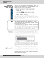
Hardware Configuration
An interruption during the update of the hardware configuration might have the effect that the unit cannot be started
again, the display is blank. In this case the unit has to be
opened and a jumper has to be set.
Connect the pins 11 and 12 on JP4 with a jumper. When
the unit is switched on again, a boot menu is shown. In
this setting each file can be reloaded using the external
update software.
Warning
The jumper has to be removed after the update!
Boot Software
The update of the boot software is realized in two phases.
In the first phase the software is downloaded from the PC to
the unit. If the update is interrupted during the first phase,
the unit only has to be started again.
The software is programmed into the unit during the second phase. This takes about 5 seconds. This process can
only be interrupted by switching the unit off or by a power
supply failure. After this interruption the unit cannot be
started again, not even by the above described emergency
start. It can only be reloaded by ORBAN Europe GmbH in
Ludwigsburg/Germany.
22
E
OPTICODEC
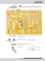
OPTICODEC
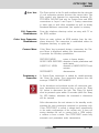
Jumper Settings
Important
Jumper Settings
on the Main Board
Input Impedance
Attention
Unplug power supply cable before opening the unit!
Switching over the input impedance ANALOG INPUT
(pls. see page 11)
Jumper JP 201/202 1 + 2 set: 600 Ohms
2 + 3 set:
10 kOhms
Switch over
RS232/RS422
Switching over from RS232 to RS422
(pls. see page 13)
Jumper JP3
OPTICODEC
1 + 2 set: REMOTE port operates
in RS422
1 - 2 open: REMOTE port operates
in RS232
E
23
/04)#/$%#0#2EMOTE
$ATA)NPUT
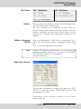
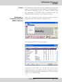
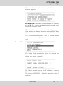
Data Input
In standby mode select ‘Data Input’ from the main menu
or alternatively the 'Data/Edit local directory' pulldown
menu..
The telephone directory appears (ISDN/IP Directory).
The window and columns widths are variable and can be
modified with the mouse.
Creating a
New Recipient
%
Open the input mask by clicking onto the function ‘New’.
Here you have the choice between ISDN or Ethernet.
/04)#/$%#
OPTICODEC PC Remote
Data Input
ISDN Connection
Depending on the number of installed ISDN modules, the
writeable input fields are represented white. Two B-channels are available for each ISDN module. Activate an input
using the mouse. The positioning marker of the cursor
blinks when the number can be entered. Move between
ISDN input fields using the tab key.
Once the ISDN numbers have been entered, you can assign
a name to the recipient (max. 49 characters).
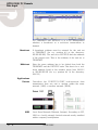
Edit Recipient
The ISDN/IP address directories of the connected ORBAN
OPTICODEC 7600, OC 7400, CTAXI or PAN-PRO can easily
be imported and exported via the 'Data' menu to your PC
for more efficient management.
Select the entry you want to process from the ISDN/IP directory using the 'Edit' key or with a mouse double-click.
To delete a recipient click with the left mouse button onto
the entry in the ISDN/IP directory you would like to delete
and press the 'Delete' key..
Deletion takes place after confirming with the ‘OK’ key.
Alterations of the default audio configuration can be made
by clicking onto the ‘Change’ key.
The configuration menu of the audio parameters which are
assigned to the current entry appears. By activating the
arrows (left-right) you can change the pre-settings.
OPTICODEC
E
25
/04)#/$%#0#2EMOTE
$ATA)NPUT
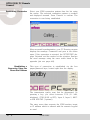
Algorithm
The 'Algorithm' menu item is used for presetting the desired
data reduction procedure on outgoing calls.
By pressing the arrow keys, you can select between Layer 2,
Layer 3, G.722, G.711 and 4SB ADPCM (optional).
ISDN Sync
The 'ISDN Sync' menu item is used to set the desired
synchronisation procedure of the partner codec.
The available sync modes for Layer 3 are:
AUTO – automatic codec detection
MusicTAXI (MusicTAXI sync for 1 to 6 B-channels)
NO SYNC for the use of 1 x B-channel
NO SYNC (INV) for the use of 1 x B-channel
ZEPHYR (Telos sync for 2 B-channels)
For Layer 2:
AUTO – automatic codec detection.
MusicTAXI (MusicTAXI sync for 1 to 6 B-channels)
NO SYNC for the use of 1 x B-channel
NO SYNC (INV) for the use of 1 x B-channel
PRIMA (CCS sync for 2 B-channels)
AETA (for 4SB ADPCM; optional)
The activation for AETA sync and 4SB ADPCM algorithm
(not included in the standard delivery) is performed as
described on the page 20.
Bitrate
%
According to the setting of the algorithm and the number
of outgoing B-channels, the transfer rate is set here: 64,
128, 192, 256, 320 or 384 kbps for layer 2 and 64, 128, 192,
256 and 320 kbps for Layer 3.
/04)#/$%#
OPTICODEC PC Remote
Data Input
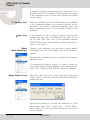
Samplingrate
The 'Samplingrate' menu item is used for setting the desired
sampling frequency on outgoing calls.
You can choose between: 16, 22.05, 24, 32, 44.1, 48 kHz,
AUTO (the sampling frequency of the addressing device
is used)
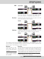
Audio Mode
The 'Audio Mode' menu item is used for setting the desired
audio behaviour on outgoing calls.
Mono
mono signal. The left input is used..
Dual Mono
two different signals which do not jam each
other, e.g. left channel: original soundtrack;
right channel: translation
Stereo
as for Dual Mono, each channel is encoded
separately, but with the difference that a
channel is allocated excess bits if less or
no audio is transmitted on the other channel
(i.e. bit distribution as needed).
Joint Stereo
comparable with MS stereophony (middle/
side signal). Encodes the sum between left
and right and the difference between left
and right; these are encoded and transmitted
separately (subjectively better quality at low
data rates).
Audio Input
The 'Audio Input' menu item is used for setting the desired
audio input on outgoing calls. You can choose between:
Analog and AES/EBU and S/PDIF.
Userdata
The menu item 'Userdata' is used for setting the desired
ancillary data on outgoing calls.
You can choose between:
OFF (no ancillary data is transferred)
1200, 2400, 4800 baud with Layer 2 and 3.
Note
If the ancillary data is switched off (OFF), no remote effect
signals are transmitted either.
Between OPTICODECs, the smallest preset baud rate of
the ancillary data is used in the context of the device
handshake.
OPTICODEC
E
27
/04)#/$%#0#2EMOTE
$ATA)NPUT
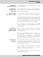
G.722 Connection
with H.221
or SRT Sync
If you enter a G.722 partner in the ‘Data Input’ menu, please
observe the following order:
1.
2.
3.
Enter the ISDN number.
Enter G.722 in ‘Algorithm’
Determine the Sync modes in ‘ISDN Sync’.
Now H=H.221 or S=SRT is displayed in the directory for
the selected SYNChronisation procedure.
%
X.21 Connection
To activate the X.21 interface, enter an 'X' in the ISDN field
(e. g. position #11 in directory).
Codec Loop
If the input fields are empty, the OPTICODEC starts the
‘codec loop’ mode. This serves as a test for the coded
audio signal (without ISDN, e. g. position #12.)
/04)#/$%#
OPTICODEC PC Remote
Data Input
Ethernet Connection
Should an Ethernet connection be desired, please activate
the radio button for Ethernet. Enter the target address
and, for easier identification, also enter the name of your
connection partner.
You may enter both IP address and plain-text names*
(* only if a name server also exists).
IP Connection
In the same way as the description of ISDN connections,
you can set the audio parameters for the planned connection here. The menu guides you through algorithm (Layer
2 and Layer 3), mode, bitrate, and finally userdata.
Mode
The target address to be entered is dependent on the
desired transmission mode. The entries can be changed
by activating the arrow keys. The following IP connection
types are possible: Point-to-Point, Transmit and Receive.
Point-to-Point
A bi-directional connection between two units. TCP is
utilised as the protocol, possible transmission errors are
corrected to a certain degree by this protocol. These
entries are marked with an “X” in the Sync column of the
directory.
Should ‘Point-to-Point’ be set for the mode, then the IP
address of the partner unit is to be entered.
Transmit
The unit functions as a transmitter for broadcast or multicast transmission. UDP is utilised as the protocol, possible
transmission errors can not be corrected. In this mode,
the unit transmits to one or more receivers. Bidirectional
UDP connections are possible when both units are set to
TRANSMIT. Marked with “T” in the directory.
Receive
The unit functions as a receiver for a broadcast or a multicast transmission. This setting is the opposite of TRANSMIT.
Marked with “R” in the directory.
OPTICODEC
E
29
/04)#/$%#0#2EMOTE
$ATA)NPUT
For TRANSMIT and RECEIVE it is to be distinguished
whether a broadcast or a multicast transmission is
desired.
Broadcast
A broadcast address must be entered for the unit set
to TRANSMIT (for e.g. position #2 in the directory:
255.255.255.255). The unit set to RECEIVE dials the address
of the partner unit. This is the address of the unit set to
TRANSMIT.
Multicast
Here the same address has to be dialed from both the
TRANSMIT and the RECEIVE units. This has to be a multicast address found in the number range from 224.0.0.0
to 239.255.255.255 (for e.g. position #4 in the directory:
234.0.0.0).
Applications
Unicast
LAN
%
Describes the POINT-TO-POINT bi-directional data
transmission from one unit to another within the same
network (LAN) or another network (WAN).
Local Area Network (Ethernet, Intranet). According to ISO,
LAN is a locally strongly limited network mostly installed
within company headquarters.
/04)#/$%#
OPTICODEC PC Remote
Data Input / Applications
WAN
Wide Area Network. Long-distance data traffic networks
such as the Internet or connections using ISDN units.
Broadcast
Describes the data transmission from one unit to all of the
other units within the same network.
Multicast
Describes the data transmission from one unit to all of the
others within the same network or another network.
The multicast mode should preferably be used instead of the broadcast mode. Important is therefore the agreement between connection partners of suitable application and
protocol types. The following is a brief comparison:
Multicast
Only the units of a multicast group receive the
data, all other units remain
unloaded.
A large selection of routers
which support multicast
are available.
Broadcast
All units within the network receive the same packet which
they then have to analyse even when the packet has not
been directed to all units. This results in an unnecessarily
high processing power load. Several broadcast transmissions
could possibly even cause disturbances in these units.
Routers which are able to direct broadcast transmissions
to other networks are not customary.
OPTICODEC
E
31
/04)#/$%#0#2EMOTE
$ATA)NPUT
Tip
The local ISDN/IP directory is saved in the 'OpticodecRemote‘ program directory as a 'num.dat‘ file. This directory
can be easily exported to any number of PCs, hence
saving time by copying the same address book directory
to all of them.
Saving the Unit
ISDN/IP Directory to
your PC Harddisk
Use the feature ‘Save directory to disk’ to store the ISDN/IP
directory of your unit on PC.
Do this by selecting the file format you require, either Directory File (*.DIR), Text separated Files (*.TXT) or Comma
separated Files (*.CSV) and importing the address book
into MS Word or Excel, for example. These file formats
can also be exported to the unit.
However, the program’s own editor can run only *.DIR
file formats.
Edit saved directory
%
The entries can be edited, newly entered, deleted and
sorted by means of the ‘Edit saved directory’ function.
/04)#/$%#
OPTICODEC PC Remote
Data Input
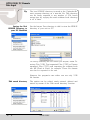
Loading
ISDN/IP Directory
to a Unit
Click onto ‘Load directory to unit’, locate the desired *.DIR
file and finally activate the ‘Open’ key.
Select from the directory the desired file format.
All 96 entries (connection partners) with their names, ISDN
numbers/IP addresses and set audio parameters are now
loaded to the unit.
It is irrelevant whether all or only some of the entries have
been occupied or whether they are all or partly vacant; or
whether the connected unit is an OPTICODEC 7600, OC
7400, CTAXI or PAN-PRO.
Exporting the directory can easily be repeated should it
fail because of for e.g. a power down or power failure.
OPTICODEC
E
33
/04)#/$%#0#2EMOTE
3YSTEM3ETUP
Configuration of the
connected OPTICODEC
in System Setup
Select 'System Setup' from the 'Unit' pulldown menu. The
basic configuration menu of the connected OPTICODEC
differs in appearance depending on the unit type and its
equipment.
TCP/IP Basics
In this menu item the basic settings of the unit within the
network are entered.
Local IP Address
In the data entry mask, enter the IP address of your
OPTICODEC. Be aware that every connection to the network
must possess its own unique IP address.
Subnet Mask
The 'Subnet Mask' is used to subdivide a network into
smaller subnets, in order to reduce the data traffic to the
subnets and/or permit better administration of the data
traffic.
Default Gateway
The data exchange occurs between the various nodes
in the network with complete transparency to the user.
However, the IP software detects when a data packet is
intended for a different subnet and sends it to the corresponding gateway.
If necessary, you can enter the IP address of a router here.
Otherwise, 0.0.0.0 must be entered.
You will be informed of the IP address, Subnet Mask and
Default Gateway by your network administrator.
%
/04)#/$%#
OPTICODEC PC Remote
System Setup
Dialing
Dialing Attempts
This menu item serves for setting the desired dialing
attempts. You can select between 1 ... 5 and INFINITE.
Dialing Delay
This menu items serves for setting the desired time between
dialing attempts (between 10 and 360 seconds).
Redialing Attempts
This menu item serves for setting the desired redialing
attempts, if a connection had not been disconnected by
the calling OPTICODEC. You can select between 0 ... 9
and INFINITE.
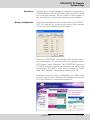
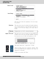
TCP/IP Audio
The settings for audio transmission over the network are
found in this menu.
Buffer Management
This buffer is used to bridge short interruptions in the data
transfer. The size of the buffer (which temporarily holds
the data from the network) can be influenced.
OPTICODEC
E
35
/04)#/$%#0#2EMOTE
3YSTEM3ETUP
To ensure the most secure transfer possible, the maximum
value (bar all the way to the right) should be set; however,
this results in a longer delay.
If more value is placed on having a shorter delay, then the
bar can be moved to the left; however, this has a negative
impact on the transmission security.
To permit the best possible transmission security with a
short delay, you should ensure that no additional devices/
workstations apart from the OPTICODEC are transmitting
data over the network.
Quality of Service
Not all applications have equal status for data transfers, and
not all applications require the same high standards for data
transfers. To minimise or prevent the risk of bottlenecks
in data networks, the IP header implements the so-called
'Quality of Service (QoS)‘ in addition to the identifier fields
such as time to live, protocol and header checksum.
If the router is configured accordingly, QoS actively regulates the load status on the network and uses the available
bandwidth intelligently and effectively on the basis of data
prioritisation or bandwidth reservation.
Type
TOS (Type of Service) or DiffServ (Differentiated Service
Architecture) are the key mechanisms of QoS and are
responsible for the assessment of packet priority.
TOS
The TOS bits contain information on the ways and means
of how a datagramm should be handled by a router. An
overloaded router can, for example, on the basis of the
TOS field determine which packets are less important
(and can therefore be cancelled) and which packets must
essentially be forwarded.
Precedence Values
%
Precedence
Significance
Precedence Significance
000
Normal
011
Flash
010
Priority
100
Flash Override
010
Immediate
101
Critical
/04)#/$%#
OPTICODEC PC Remote
System Setup
TOS Values
TOS
Significance
TOS Significance
0000
Normal
0010 max. Reliability
1000
min. Delay
0001 min. Monetary Cost
0100
max. Throughtput
DiffServ
DiffServ uses a new definition of the IPv4 TOS header field
and IPv6 traffic class header field.
The goal of DiffServ is to subdivide the data traffic into
service classes with different priorities, without using the
intensive signalling on each router. Each packet can be
marked and is handled and transmitted accorded to this
marking.
DiffServ Codepoints
(DSCP)
Each per-hop-behaviour (PHB) flow is determined by a
DSCP. You can choose between: Standard (Default, 'Best
Effort'), Class Selector 1-7, Assured Forwarding 11-13, 21-23,
31-33, 41-43, and Expedited Forwarding.
Note
Details and additional specifications can be found in the
generally available ‘Request for Comments’ lists (RFC1349
TOS; RFC2474 DiffServ) on the Internet
(www.rfc-editor.org).
Audio Data Encoder
This encoder configuration is taken over when the OPTICODEC is called by another OPTICODEC over IP. The
pre-settings are AUTO.
Descriptions of the individual functions can be found
starting page 26.
OPTICODEC
E
37
/04)#/$%#0#2EMOTE
3YSTEM3ETUP
Audio Port (TCP)
This menu contains the setting for audio transfer over the
network with TCP and UDP protocols.
For the OPTICODEC, the value 6136 should always be
entered.
TCP/IP Remote Control
Unit Name
For easier identification of devices on the network, the
name of your OPTICODEC must be entered here without
name length restrictions. This name is transmitted to the
'NETControl' program and shown in the device list.
Port
An important part of the TCP/IP model are the port numbers, also known as socket numbers. With these ports, it
is advised which service is desired.
One distinguishes between two categories of ports:
the so-called 'defined‘ or 'well-known ports‘, which are
assigned by IANA (Internet Assigned Number Authority)
and which cover a number range from 0 to 1023;
and the “dynamic ports”. Therefore only port numbers from
1024 to 65535 may be entered here.
For the OPTICODEC, the port number 6137 is to be entered.
A comparison between TCP/IP and ISDN:
TCP/IP
IP Address
Port
%
ISDN
ISDN Number
Bearer capability (for e.g.
telephone / data transmission)
/04)#/$%#
OPTICODEC PC Remote
System Setup
Autodetect
This function is for the automatic recognition of units using a
control software such as NETControl and can only be used
in a local area network. For the control of units outside of
the network area, this function should remain disabled.
Accept Configuration
This point determines the call accept mode of the OPTICODEC. You can set the accept mode more or less specific
for the unit and transmission permanently.
Then the OPTICODEC only accepts calls in the respective configuration. Or you can select the operation mode
AUTO(matic Codec Detection). The OPTICODEC serves as
a ‘SLAVE’ and takes over the parameters of the calling unit
automatically. The ‘AUTO’ mode is not available for ‘Audio
Input’ and ‘Userdata’. Descriptions starting page 26.
Statements about the audio compatibility (via ISDN) with
external codecs can be found on the supplied data carrier
or on the Internet at: www.orban-europe.eu.
OPTICODEC
E
39
/04)#/$%#0#2EMOTE
3YSTEM3ETUP
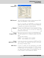
Dialing
Dialing Attempts
This menu item serves for setting the desired dialing
attempts. You can select between 1 and 5.
Dialing Delay
This menu item serves for setting the desired time between
dialing attempts (between 10 and 60 seconds).
Redialing Attempts
This menu item serves for setting the desired redialing
attempts, if a connection had not been disconnected by the
calling OPTICODEC. You can select between 0 and 5.
PBX Prefix
Under certain conditions (e.g. private branch exchange
PBX), a number that prefixes the ISDN number for dial-up
via ISDN can be entered here. To make an outside call
from a telephone system, for instance, enter 0.
A preselection number can also be entered here. The
number max not exceed five digits.
Min. length for
PBX Prefix
Using the 'Min. length for PBX Prefix‘ menu option, define
the minimum number of digits an ISDN number must have
to allow this prefix to be set before the number.
If, for example, internal extension numbers have three
digits, a 4 should be entered here.
To continue to enable internal calls, PBX dialling codes for
ISDN numbers with less than four digits are ignored.
%
/04)#/$%#
OPTICODEC PC Remote
System Setup
ISDN
Configuration
ISDN Protocol
The OPTICODEC has two ISDN D-channel protocols: EURO
(DSS1) and NATIONAL 1 (North America).
For use in the USA, the OPTICODEC is equipped with
'IMD4‘ type ISDN modules. This is necessary if additional
U interfaces are required for North America.
Warning
Decisive is the ISDN protocol of your connection, not the
one of the partner unit! You can alter the settings by
pressing the arrow keys.
Accept
Telephone Calls
This menu item serves to define the OPTICODEC behavior when operated at a S0 connection together with other
units.
You can select between:
ALWAYS every telephone call is accepted
NEVER every telephone call is rejected.
Accept
MPEG/G.722 Calls
In this menu item the call acceptance for MPEG and G.722
calls is defined. The settings are the same as the menu
item (Accept Telephone Calls).
MSN Check
In case of a passive call, the interrogation of the MSN
number can be activated or switched off. If 'YES' is entered
for MSN check, the called number is compared to the
one which has been entered in Local Numbers. The call
is only accepted, if both numbers are identical.
OPTICODEC
E
41
/04)#/$%#0#2EMOTE
3YSTEM3ETUP
In case of EURO ISDN, the MSN is usually the ISDN number of your connection without the area code, in case of
private exchanges only the number of your extension.
The ‘YES’ option should only be activated if, in addition
to the OPTICODEC, other devices (e.g. a telephone, fax
machine, PC card) must also be operated on the same
ISDN connection.
Warning
ISDN Interface
The incorrect configuration of only one unit might result
in the rejection of all calls
Via this menu item, the S0 and U interfaces used for the
transfer are selected:
S0 PMP
(Point-to-Multipoint)
S0 PP
(Point-to-Point)
U PMP
(Point-to-Multipoint)
Number Prefix for
incoming calls
for multiple device connection.
(This is the usual connection
type.)
for equipment connection
for North America only
(using a ISDN module
type 'IMD4').
These settings concern incoming calls for OPTICODEC 7200
and 7400. If the 'Add PBX Prefix‘ option is set to 'YES‘, the
number from the PBX Prefix (see 'Dialling‘, page 40) is inserted before the number for incoming calls. The minimum
number length applies here too. This setting is required
only for those ISDN systems that do not automatically add
the ISDN number.
For direct S0 connections with EURO ISDN, the leading
zeros in the ISDN numbers are not transferred for incoming
calls, e.g. 7141226622. This can be corrected by means of
the following entries.
If a 0 is entered for 'National Calls‘, this is added here.
The same applies for 'International Calls‘, where 00 is to
be entered in Germany.
When these digits are entered, the ISDN number required
to make the call will actually be displayed.
%
/04)#/$%#
OPTICODEC PC Remote
System Setup
Local Numbers
The ISDN numbers entered here are sent when the connection has been established. Under certain conditions
(e.g. private branch exchange (PBX)* type), the individual
ISDN number must be entered.
S0 without PBX*
1 x unit only
n x units
can remain vacant
or
ISDN number
without area code
ISDN number
without area code
and
MSN Check
activated
S0 on PBX*
can remain vacant
or
only the No. of
your extension
only the No. of
your extension
and
MSN Check
activated
(Test Called Number)
Note
If a local number is required, then all of the entry windows
must always be confirmed.
SPID Numbers
The identification numbers entered here are sent when the
connection has been established. They are only necessary when operating the OPTICODEC on US and Canadian
networks.
The identification numbers are entered and allocated as
described in ‘Local Numbers’.
You will be informed of the SPID number by your ISDN
provider. These input fields otherwise remain empty.
OPTICODEC
E
43
/04)#/$%#0#2EMOTE
3YSTEM3ETUP
I/O Levels
This menu item serves for setting the analog Input and
Output levels for the left and right channels.
Ex-factory the setting is +12 dBu, the headroom is 0 dB.
This means: input level = output level = 12 dBu. With a
mouse click on the ‘up’ and ‘down’ arrow keys the level
value can be altered.
Misc
Alarm Signals
If these signals are switched OFF, the relevant switching
information of the OPTICODEC inputs is transferred to the
partner unit. Otherwise you can select between:
CON
DIS
CON+DIS
%
The signal is set to pin 19 once the decoder
has been synchronized i.e. when the connection
is ‘OK’.
The signal is set to pin 18 if the line has been
disconnected from the partner unit or because
of an ISDN error.
Both signals are set.
/04)#/$%#
OPTICODEC PC Remote
System Setup
Level Range
This menu item allows the adjustment at the level range:
50 or 80 dB.
Headroom
This menu item serves for setting the desired headroom.
You can select between 0 and 20 dB in 1 dB steps. Exfactory the setting is 0 dB.
The scale display in the online menu is moved.
Warning
External Sync Input
Clipping limit at 0 dB + selected headroom!
The OPTICODEC has a sample rate converter at the audio
input and output. For the external synchronization of the
digital output you can select between:
DISABLED
Word clock is generated from the ISDN
transmission clock
DIGITAL IN Word clock is generated from the AES or S/PDIF
input signal
SYNC IN
Word clock is taken over from SYNC IN.
Backlight
This function serves to set the display background lighting
of the connected unit:
ALWAYS ON
background lighting is always on
ON CONNECT the background lighting switches on
once a connection has been established
or when the ‘System Setup’ or ‘Data
Input’ menus have been called up.
The lighting switches off shortly after
returning to the main menu.
Automatic
Connection Start
When ‘Auto connect after power up’ check box is activated,
the unit automatically begins establishing a connection once
it has been switched on. The configuration used here is
set up using the ‘Config’ key.
OPTICODEC
E
45
/04)#/$%#0#2EMOTE
3YSTEM3ETUP
Backup Settings
In the 'Backup Settings' mode you can allocate an entry of
the ISDN directory to each input port of the Alarm/Control
Interface.
To do this, you must select the requested input port. Press
the ‘Cfg’ (Configuration) key to allocate an ISDN number
to this input port.
This ISDN number complies in all parameters to the respective entry in the ISDN directory.
In the following example, the entries IN1 to IN 4 for backup are utilised.
The entries IN5 to IN8 have not been allocated and are
transmitted transparently to the opposite side. A feedback
to confirm whether connection has been established takes
place over the respective outputs of the Alarm/Control
Interface. When, for example, a connection has been
established with IN2, the output OUT2 is activated once
the connection has been established and the decoder has
been synchronised.
Further information on applications of Backup Settings can
be found on page 75.
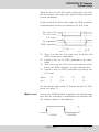
X.21 Clock Monitoring
%
To do this the ‘No X.21 clock’ must be activated. Enter
with the corresponding Cfg button, the ISDN number of
the partner unit which should be dialed in case of error.
The desired configuration is also entered.
/04)#/$%#
OPTICODEC PC Remote
System Setup
When the unit is in the X.21 mode and the X.21 clock fails,
the unit returns to the main menu and the ISDN connection
is then established.
As soon as the X.21 clock is active again, the ISDN connection
is disconnected and the unit returns to the X.21 mode.
X.21 clock OK
No X.21 clock
X.21 mode
No connection
ISDN connection
T1: Time, how long the X.21 mode must fail before the
ISDN connection is established.
T2: Length of time for an ISDN connection to be established.
T3: Time, how long the X.21 clock must again be active
before the ISDN connection is again disconnected.
T4: Length of time for ISDN connection and change into
X.21 mode.
Times:
(sec.)
T1
2
T2
5-30
T3
5
T4
1-2
For the settings when using OC Remote with the OC 7400,
please see page 77.
Mode: Level
As soon as a switching signal is applied to the corresponding
input INx, the connection is established and continues until
the switching signal is disconnected.
OPTICODEC
E
47
/04)#/$%#0#2EMOTE
3YSTEM3ETUP
Saving the Units
System Setup to Your
Harddisk
Similarly to that of the ISDN/IP directory (pls see page
30), there is alternatively the possibility to save the system
configuration of the OPTICODEC onto your PC harddisk
for archive purposes, for example.
Use the ‘Save System Setup to Disk’ feature to store the
unit specific *.CFG data file in a folder of your choice.
Loading System Setup
to a Unit
By using the ‘Load System Setup to Unit’ feature, the system
configuration already stored on your PC can be loaded
onto the OPTICODEC units.
Locate the *.CFG data to be loaded and press the 'Open'
key.
Any number of OPTICODEC units can easily be configured with identical ‘System Setup’ settings using this
procedure.
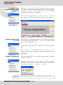
Default Configuration
With this menu item all previous configurations are reset
to those ex-factory.
After the safety query, confirm with the ‘OK’ key should
the default procedure be carried out or use ‘Cancel’ should
you wish to cancel the command to default.
Warning
%
This process can not be reversed after confirmation!
/04)#/$%#
OPTICODEC PC Remote
Connect
Connect
The respective connection can be established quickly and
easily. A pre-requisite for the connection establishment is
the correct initializing of the OC Remote software with
the connected OPTICODEC. This is confirmed with the
‘Standby’ status message in the program screen.
Establishing a
Connection Using the
ISDN/IP Directory
Select the ‘Connect’ key from the main menu or choose
alternative the 'Unit/Connect'. pulldown menu.
The present ISDN/IP directory appears.
Assigned to each entry you will find the name of your
connection partner, the ISDN number, IP address or target
address, the selected audio parameters as well as the sync
mode of your partner unit.
OPTICODEC
E
49
/04)#/$%#0#2EMOTE
#ONNECT
Establishing Connection
Select your ISDN connection partner from the list using
the mouse. The selected connection partner is marked
and displayed inverted. Press ‘Connect’ to confirm. The
connection is now being established.
After successful synchronization, your OC Remote program
displays the message ‘Connected’ and goes to the online
menu. If the connection is rejected, the OPTICODEC displays ‘Rejected’ and the reason for the rejection. Analyse
the error message using the error codes listed in the
appendix (pls. see page #44).
Establishing a
Connection Using the
Direct-Dial Buttons
This type of connection is established via the four
preprogrammed keys, located right from the display.
The transmission quality must first be determined. By
pressing a key, you select between G.711 (3.1 kHz,
telephone), G.722 (H.221 or SRT), Layer 2, Layer 3, AAC*
or 4SB ADPCM* (*optional).
The entry menu then requests the ISDN number, target
or IP address which is entered with the numeric keypad
as usual.
%
/04)#/$%#
OPTICODEC PC Remote
Connect
Note
The connection parameters for Layer 2 and Layer 3 are
determined as follows: Only entry of the first ISDN number.
64 kbps, 48 kHz, Mono, User Data 1200 baud.
For the entry of two ISDN numbers: 128 kbps, 48 kHz,
Joint Stereo, User Data 1200 baud.
The audio input used is taken from the Accept Configuration. The ISDN Sync used is always AUTO.
Automatic
Connection Start
On switch-on or e.g. after a power outage, the OPTICODEC
automatically establishes a connection provided that the
‘Auto connect after power up’ check box is activated and
a target number or address has been allocated.
Connection Monitoring
After the establishment of the connection and the exchange
of the transmission parameters, the online transmission
menu appears on the display.
It shows information about the send and receive levels,
connection duration and the set headroom and synchronisation.
OPTICODEC
E
51
/04)#/$%#0#2EMOTE
#ONNECT
In addition, together with the send (Tx) and receive configuration (Rx), the IP address / ISDN number (according
to the connection type) of your codec partner are shown
on the display.
$ Currency Icon
After the establishment of an ISDN connection, in addition
to the connection duration, the currency icon ($) is also
activated. The actually incurred connection costs can
only be displayed on an S0 from Deutsche Telekom after
activation.
Sync Icon
If the decoder of the connection partner receives the
correct data, then this is confirmed by the Sync icon in
the Rx path. The Sync icon is only available between
OPTICODECs during Point-to-Point or ISDN connections in
Layer 2 and Layer 3.
Adjust
Audio Parameters
During a live connection, you can place a query without
interrupting the line and change the audio parameter
settings.
This function is available from the 'Unit/Audio Data Encoder‘
pulldown menu.
If a connection is made in 'Layer 2‘ or 'Layer 3‘ mode, you
can toggle between these algorithms. The parameters between G.711, G.722 and 4SB ADPCM cannot be changed.
Adjust Audio Levels
This menu item serves for setting the analog Input and
Output levels for the left and right channels without interrupting the line.
Ex-factory the setting is +12 dBu, the headroom is 0 dB.
This means: input level = output level = 12 dBu. With a
mouse click on the ‘up’ and ‘down’ buttons the level value
can be altered.
%
/04)#/$%#
OPTICODEC PC Remote
Connect
Establishing a
Connection with X.21
From the Directory, select an entry with ‘X.21’ as the digit
of the ISDN number.
Establishing a
Connection with
Codec Loop
From the Directory, select an entry without an ISDN number. The connection is established via the Directory, 'Quick
Dial' or 'Direct Dial Buttons'.
Call Acceptance
with ISDN Sync AUTO
The function ‘AUTO’ (Automatic Detection of the calling Unit)
is entered in the ‘System Setup / Accept Configuration’.
The function ‘ISDN Sync AUTO’ has priority over all other
entries. This means if ‘AUTO’ is set and the OPTICODEC
is called by any competitor codec, the OPTICODEC sets
itself to the audio parameters incl. sync modes of the calling
unit automatically. This might last up to 30 seconds.
The set parameters of the ‘System Setup / Accept Configuration’ are taken over if the OPTICODEC is called by
an OPTICODEC.
Establishing a
Connection with
ISDN Sync AUTO
When a connection partner is entered into the telephone
directory, ISDN Sync and audio parameters can be preset
in the configuration.
However, an entered ‘ISDN Sync AUTO’ has priority over
all other settings. This means that if a connection has
been established to a competitor unit, the OPTICODEC
automatically adapts itself to the audio parameters incl. sync
modes of the remote unit. This might last up to 30 sec.
Terminating the
Connection
An existing ISDN and Point-to-Point connection is ended
by pressing the ‘Disconnect’ key. After disconnection, the
message ‘REMOTE DISCONNECT’ appears on the display
of your connection partner.
In the broadcast and multicast modes all connection
partners, transmitters and receivers have to press the
‘Disconnect’ key to disconnect the link.
The OPTICODEC goes into standby mode and waits for
further connection requests.
OPTICODEC
E
53
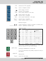
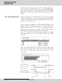
OPTICODEC 7400
Front Panel / Keypad
The OPTICODEC 7400 is a fully duplex ISDN audio codec
with an Ethernet interface for the remote control of the
unit and the possibility to distribute audio over networks
such as Intranet, ATM etc. Configuration and operation of
the unit takes place using the numeric keypad and/or the
control software OC Remote and NETControl.
Further information on the audio and data interfaces are
found starting from page 12 of this manual.
Graphical
Diplay Module
with integrated LCD controller, 128 CG-ROM and display
W x H x D: 180.0 x 65.0 x 12 mm
Visible Range: 132.0 x 39.0 mm
Display RAM: 8 kByte
240 (horizontal) x 64 (vertical) dots
By 6 x 8 dots per letter: 40 letters x 8 lines, 64 columns
Explanation of
Keypad Symbols
OK
ISDN
ERR
OK
UP
54
E
indicates a correct or rejected connection
of the OPTICODEC. Release by pressing ‘Hang Up’.
Blinks when a software update is being carried out.
cursor moves upwards
DOWN
cursor moves downwards
ENTER
selected function is confirmed
OPTICODEC
OPTICODEC 7400
Front Panel / Keypad
G.711
activates the G.711 algorithm
Copy
copies a telephone number
G.722
PgUp
cursor jumps to the left
activates G.722 algorithm
cursor jumps upwards to next page
Layer 2
PgDn
cursors jumps to the right
activates Layer 2 algorithm
cursor jumps downwards to next page
Layer 3
Delete
activates Layer 3 algorithm
deletes marked number or letter
Numerical keypad
0,1,2...9 / A,B,C...Z
contrast adjustment of display (available in standby only)
number / alphabetic character input.
Assignment table:
Key
Character
1
1
. (point)
/
2
2
A
B
3
3
D
E
4
4
G
H
5
5
J
K
6
6
M
N
7
7
P
Q
8
8
T
U
9
9
W
X
0
0 , (comma) + (plus)
(space)
C
F
I
L
O (as ‘Otto’)
R
S
V
Y
Z
- (minus)
Other special characters are attainable in certain input
fields by using the UP and DOWN buttons.
QUICK DIAL
*
HANG UP
Cancel
connection establishment via quick dial
X for X.21 connections and possibly required for entry of
sub-address
disconnection
cancels the last action
OPTICODEC
E
55
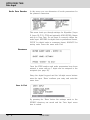
OPTICODEC 7400
Data Input
Data Input
After switching the unit on and after a short initializing
sequence the 3 pages of the basic configuration menu of
the OPTICODEC 7400 appears (see also „Status Messages“,
page 82).
After selecting the menu ‘Data Input’ and confirming with
the ‘Enter’ key, the directory for IP addresses, ISDN numbers, names and audio configurations appears. Here a max.
of 96 entries can be stored.
Enter New Recipient
Choose a free position to enter a new connection partner or
choose an already existing entry for a possible correction.
Confirm with the ‘Enter’ button.
Connection Mode
First choose the desired connection mode in the network.
You can select between ISDN/X.21 or Ethernet.
56
E
OPTICODEC
OPTICODEC 7400
Data Input
ISDN Connection
The option ‘ISDN/X.21’ must be selected in the line for
connection type if an ISDN connection is required.
ISDN Number
Depending on the number of ISDN modules, input fields
between ISDN#1 and ISDN#4 are displayed.
Entries are made using the numerical keypad. These may
have a maximum of 22 digits. Correct and erase entries
using the DEL button and move between ISDN input fields
using the ‘Enter’ button.
Note
The ISDN Sync option is available once an ISDN number
has been entered.
ISDN Sync
The ‘ISDN Sync’ menu serves for selecting the codec of
your connection partner. The possible Sync modes are:
MusicTAXI (MusicTAXI Sync for 1 to 4 B-channels)
PRIMA (CCS Sync for 2 B-channels)
ZEPHYR (Telos Sync for 2 B-channels)
AETA (for 4SB ADPCM algorithm; optional)
NO SYNC when using 1 B-channel
NO SYNC (INV) when using 1 B-channel
AUTO - Automatic Audio Codec Detection
The release of the AETA sync and the 4SB ADPCM algorithm (not contained in the standard scope of delivery)
takes place via the 'OC Remote' or 'NETControl' software
and depends on the unit model and its serial number. Each
unit receives a unique key code (pls. see page 20).
For information on the Zephyr, CDQ Prima and AETA
Hifiscoop pre-settings please see the chapter 'Audio compatibility via ISDN' on the data medium included in the
delivery scope.
OPTICODEC
E
57
OPTICODEC 7400
Data Input
Audio Data Encoder
In this menu you can determine all audio parameters for
the planned connection.
This menu leads you through settings for Algorithm (Layer
II, Layer III, G.711, G.722 and optionally 4SB ADPCM), Bitrate
and up to User Data. Do not forget to correctly define the
audio input: AES/EBU for digital units in professional format,
S/PDIF for digital units in consumer format, ANALOG for
analog units. Leave the menu with ‘Exit’.
Shortname
Once the ISDN number and audio parameters have been
entered, a name with up 7 digits can be assigned to the
recipient (see page 55).
Using the digital keypad and the left-right arrow buttons
enter the input. ‘Enter’ confirms your entry and exits this
menu item.
Store & Exit
By pressing the ‘Enter’ button the settings made in the
ISDN/IP directory are saved and the 'Data Input' menu
item is exited.
58
E
OPTICODEC
OPTICODEC 7400
Data Input
IP Connection
Should an Ethernet connection be selected, you can then
set the desired IP connection.
The following connenction modes are possible:
Point-to-Point
A bi-directional connection between two units. TCP is
utilised as the protocol, possible transmission errors are
corrected to a certain degree by this protocol. These
entries are marked with an “X” in the Sync column of the
directory.
Transmit
The unit functions as a transmitter for broadcast or multicast transmissions. UDP is utilised as the protocol, possible
transmission errors can not be corrected. In this mode,
the unit transmits to one or more receivers. Bidirectional
UDP connections are possible when both units are set to
TRANSMIT. Marked with “T” in the directory.
Receive
Here the unit functions as a receiver for broadcast or
multicast transmissions. This setting is the opposite of
TRANSMIT. Marked with “R” in the directory.
Return to the ‘Data Input’ menu item by using the ‘Exit’
feature.
IP Address
Changes in a connection result in the automatic alternation
between the ISDN number entry and the IP address in
the third line.
OPTICODEC
E
59
OPTICODEC 7400
Data Input
Here you enter the IP addresses for the desired connection. The addresses to be entered are dependent on the
desired transmission protocol:
POINT-TO-POINT mode: The local IP address of the partner
unit is to be entered.
For TRANSMIT and RECEIVE it is to be distinguished
whether a broadcast or a multicast transmission is
desired.
Broadcast
A broadcast address must be entered for the unit set to
TRANSMIT (for e.g. position #5 in the directory). The unit
set to RECEIVE dials the address of the partner unit. This
is the address of the unit set to TRANSMIT.
Multicast
Here the same address has to be dialed from both the
TRANSMIT and RECEIVE units. This has to be a multicast address found in the number range from 224.0.0.0
to 239.255.255.255 (for e.g. position #6 in the directory:
234.0.0.0)
Applications and further descriptions are found up to p. 28.
60
Audio Data Encoder
Identical to the ISDN connections described, here the audio
parameters for an intended connection can be specified.
Shortname
Here the shortname of a partner audio codec can be
entered with a maximum length of 7 characters for easier
identification.
Store & Exit
This feature stores the entries made in the ISDN/IP
directory and exits the ‘Data Input’ menu item.
E
OPTICODEC
OPTICODEC 7400
System Setup
System Setup
By pressing the UP/DOWN buttons, select System Setup from
the main menu and confirm with the ‘Enter’ button.
Accept
Configuration
This sets up the call accept mode of the OPTICODEC.
First you can set the accept mode Audio Data Encoder for
the unit and transmission more or less specific and permanently. Then the unit only accepts calls in the respective
configuration. Or you can select the operation mode AUTO
(Automatic Codec Detection). Then the OPTICODEC serves
as a ‘slave’ and takes over the parameters of the calling
unit automatically.
The ‘AUTO’ mode is not available for ‘Audio Input’ and
‘Userdata’.
Algorithm
The 'Algorithm' menu item serves for setting the desired
data reduction procedure. You can select between:
Layer 2, Layer 3, 4SB ADPCM* (*optional) and
AUTO (G.711/G.722 calls are also accepted).
ISDN Sync
The 'ISDN Sync' menu serves for setting the desired synchronization procedure.
OPTICODEC
E
61
OPTICODEC 7400
System Setup
The possible Sync modes are:
MusicTAXI (MusicTAXI Sync for 1 to 4 B-channels)
PRIMA (CCS Sync for 2 B-channels)
ZEPHYR (Telos Sync for 2 B-channels)
AETA (for 4SB ADPCM algorithm; optional)
NO SYNC when using 1 B-channel
NO SYNC (INV) when using 1 B-channel
AUTO - Automatic Audio Codec Detection
The release of the AETA sync and the 4SB ADPCM algorithm (not contained in the standard scope of delivery)
takes place via the 'OC Remote' or 'NETControl' software
and depends on the unit model and its serial number.
Each unit receives a unique key code.
Warning
If a sync other than ‘MusicTAXI’ or ‘AUTO’ is preset, G.722
calls cannot be received.
Samplingrate
The ‘Samplingrate’ menu item serves for setting the desired
sampling frequency when calls are coming in. You can select between: 16, 22.05, 24, 32, 44.1, 48 kHz and AUTO (the
sampling frequency of the calling unit is taken over).
Audio Mode
The menu item ‘Audio Mode’ serves for setting the desired
channel mode, when calls are coming in.
You can select between Mono, Dual Mono, Stereo, Joint
Stereo and AUTO (pls. s. page 27).
Audio Input
The menu item ‘Audio Input’ serves for setting the desired
audio input, when calls are coming in. You can select
between: Analog, AES/EBU and S/PDIF.
Userdata
The menu item ‘Userdata’ serves for setting the desired
ancillary data, when calls are coming in.
You can select between:
OFF (no ancillary data are transmitted)
1200, 2400, 4800 baud in Layer 2
1200, 2400, 4800, 9600 baud in Layer 3.
Note
If the transmission of ancillary data is switched off (OFF),
the alarm control signals are not transmitted either.
From OPTICODEC to OPTICODEC, the lowest preset
baud rate of the ancillary data is agreed within the unit
handshake.
62
E
OPTICODEC
OPTICODEC 7400
System Setup
ISDN
Configuration
ISDN Protocol
The OPTICODEC has several ISDN D-channel protocols.
Please make sure that you have selected the correct protocol. Decisive is the ISDN protocol of your connection, not
the one of the partner unit! Alter the settings by pressing
the 'Enter' key.
ISDN Interface
In this menu option the S0 and U interfaces to be used for
the transmission are selected. The function is only available if IMD4 modules are installed in the OPTICODEC.
Possible settings are:
S0 PMP (Point-to-Multipoint), S0 PP (Point-to-Point)
and U PMP (Point-to-Multipoint) (pls. see page 42.)
Local Numbers
The ISDN numbers which are entered here, are sent to the
ISDN network when the connection has been established.
On certain ISDN networks [e.g. Private Branch Exchange
(PBX)*] the extension number has to be entered.
S0 without PBX*
1 x unit only
n x units
can remain vacant
or
ISDN number
without area code
ISDN number
without area code
and
MSN Check
activated
S0 on PBX*
can remain vacant
or
only the No. of
your extension
only the No. of
your extension
and
MSN Check
activated
(Test Called Number)
Note
Should a local number be required, then all entry fields
have to be occupied.
OPTICODEC
E
63
OPTICODEC 7400
System Setup
SPID Numbers
The SPID numbers entered here are also sent when a
connection is being established. This is necessary only
when operating on USA or Canadian networks.
The identification number input and allocation takes places
as described in “Local Numbers”.
Dialing
Dialing Attempts
Here the number of dialing attempts between 1 and 5 can
be selected.
Dialing Delay
This menu items serves for setting the desired time between
dialing attempts (between 10 and 60 seconds).
Redialing Attempts
If an existing connection is interrupted not by the dialing
OPTICODEC, but by possible ISDN problems, then here
you can define the number of redialing attempts between
0 and 5.
PBX Prefix
Under certain conditions (e.g. private branch exchange
PBX), a number that prefixes the ISDN number for dial-up
via ISDN can be entered here. To make an outside call
from a telephone system, for instance, enter 0.
A preselection number can also be entered here. The
number max not exceed five digits.
Min. length for
PBX Prefix
Using the 'Min. length for PBX Prefix‘ menu option, define
the minimum number of digits an ISDN number must have
to allow this prefix to be set before the number.
If, for example, internal extension numbers have three
digits, a 4 should be entered here.
To continue to enable internal calls, PBX dialling codes for
ISDN numbers with less than four digits are ignored.
64
E
OPTICODEC
OPTICODEC 7400
System Setup
Incoming Calls
The menu item 'Incoming Calls' defines the behavior of the
OPTICODEC during operation on a S0 connection together
with other units.
Accept
Telephone Calls
First set 'Accept Telephone Calls' to:
ALWAYS every telephone call is accepted
NEVER
all telephone calls are rejected
ASK
manual confirmation of each call is requested
by the unit.
Accept
MPEG/G.722 Calls
With the menu item 'Accept MPEG/G.722 Calls' the behavior
for incoming MPEG/G.722 calls is determined. The setting
options are described above.
Test Called Number
The 'Test Called Number‘ menu option activates the MSN
query for incoming calls. This requires the correct MSNs
of the individual connection to be entered into the ‘Local
Numbers’ menu item. The call is only accepted if the two
numbers are identical. On Euro-ISDN, the MSN is usually
the ISDN number of the connection without the dialling
code, but for PBXs it is usually the extension number only.
The ‘YES’ option should only be activated if, in addition
to the OPTICODEC, other devices (e.g. a telephone, fax
machine, PC card) must also be operated on the same
ISDN connection.
Number Prefix
(for incoming calls)
These settings concern incoming calls for OC. This setting
is required only for those ISDN systems that do not
automatically add the ISDN number. The minimum number
length applies here too. For direct S0 connections with
Euro-ISDN, the leading zeros in the ISDN numbers are not
transferred for incoming calls, e.g. 7141226622. This can be
corrected by means of the following entries.
If a 0 is entered for national calls, this is added here.
The same applies for international calls, where 00 is to
be entered in Germany. When these digits are entered,
the ISDN number required to make the call will actually
be displayed.
OPTICODEC
E
65
OPTICODEC 7400
System Setup
TCP/IP
Configuration
TCP (Transmission Control Protocol) is one of the most
important protocol specifications of the network protocols.
TCP is a connection-oriented protocol and provides a reliable, byte stream service.
This menu item determines the basic settings of the OPTICODEC for operation in the network. The settings are
subdivided into three areas:
General Settings
LOCAL IP ADDRESS
SUBNET MASK
DEFAULT GATEWAY
Settings for Remote Control
REMOTE CONTROL
Settings for Audio Transmission
AUDIO TRANSMISSION
Local IP Address
Enter the IP address of your OPTICODEC into the input
mask. Please note that each connection in the network
requires a separate and unique IP address.
66
E
OPTICODEC
OPTICODEC 7400
System Setup
Should an address be allocated twice, the following error
message appears:
abc.def.ghi.jkl is the own IP address which is currently
set and xx is a counter which displays the seconds to go
before the automatic restart.
With ‘Enter’, the menu to enter the local IP address appears.
After entering the address, the unit is restarted. With ‘Hang
Up’ the unit restarts without changing the IP address.
The unit restarts automatically after 60 seconds should
no button be operated. The IP address will not be changed.
Subnet Mask
The 'Subnet Mask' is utilised to divide the network into
sub-networks and herewith splits the amount of data exchange into several channels.
The Subnet mask is, just as the IP addresses, a binary
32-bit value and is provided by your network administrator.
The number 255.255.255.0 is normally entered for Class C
networks.
OPTICODEC
E
67
OPTICODEC 7400
System Setup
Default Gateway
The data exchange between the different cross points
of the network is transparent for the user. The IP-stack
recognizes whether a data packet is scheduled for another
network and will then address the default gateway. This
corresponds for e.g. with a router or other gateway units.
0.0.0.0 must be entered if the default gateway should not
be used.
Warning
Only when using the NETControl software:
Should the Local IP Address and/or Subnet Mask be
changed so that the unit and the PC running the NETControl
program are then situated in different networks, then this
PC no longer has access to the unit.
You will be informed of the IP Address, Subnet Mask and
Default Gateway by your network administrator.
Remote Control
The settings for the remote control of the unit over the
network are found in the menu item 'Remote Control'. Enter
the name of your OPTICODEC and the port numbers
here.
Name
This is for the easier identification of units within the
network. Enter the name of your OPTICODEC with a
maximum of 7 digits. This name is conveyed to the remote
control program (for e.g. NETControl) and is displayed in
its list of units.
When the name of a unit has been changed and confirmed
with ‘OK’, the unit will disappear from the unit list in
the remote control program for several seconds. The unit
reappears under the new name.
68
E
OPTICODEC
OPTICODEC 7400
System Setup
Port
An important part of the TCP/IP model are the port numbers,
also known as socket numbers. With these ports, it is advised
which service is desired (pls. s. ‘Port’ on page 38).
The value 6137 should always be entered for the
OPTICODEC.
Auto Detect
This function is for the automatic recognition of units using
a control software (for e.g. NETControl) and can only be
used in a local area network. This function should remain
disabled to control units outside of the network area
Audio Transmission
The settings for audio transmission over the network are
found in this menu.
Buffer Management
This buffer serves as a bridge for short-term interruptions
during transmission. The size of the buffer (which stores the
audio data) can be influenced.
For the most reliable transmission, the maximum value (bar
to the far right) should be set. This results, however, in a
greater delay.
The bar can be adjusted further to the left should a lower
delay be important but this negatively influences the transmission reliability.
OPTICODEC
E
69
OPTICODEC 7400
System Setup
To achieve the highest possible transmission reliability with
a low delay, it should be ensured that no further units are
simultaneous transmitting data within the network.
Port
Here the port number for audio transmission is entered.
Always enter the value 6136 for the OPTICODEC.
Accept Configuration
Audio Data Encoder
This encoder configuration is taken over when the OPTICODEC is called by another OPTICODEC in the mode
Point-to-Point. It may be possible to use: For Tx Layer 2,
384 kbps, 48 kHz, dual mono; for Rx Layer 3, 32 kbps, 16
kHz, mono. As opposed to the corresponding menu to call
via ISDN, here no automation is possible.
Dialing
Dialing Attempts
This menu item serves for setting the desired dialing
attempts. You can select between 1 ... 5 and INFINITE.
Dialing Delay
This menu items serves for setting the desired time between
dialing attempts (between 10 and 360 seconds).
Redialing Attempts
This menu item serves for setting the desired redialing
attempts, if a connection had not been disconnected by
the calling OPTICODEC. You can select between 0 ... 9
and INFINITE.
Quality of Service
Not all data transmission applications have the same priority
and not all of these require the same high standards for
the transfer of data. In order to minimize or avoid the risk
of data network congestion, a so-called „Quality of Service“
of QoS option has been implemented in the IP header with
acknowledgement fields such as Time to Live, Protocol and
Header Checksum.
70
E
OPTICODEC
OPTICODEC 7400
System Setup
Type
QoS (when the router has been configured accordingly)
actively regulates traffic in the net and utilises the available
bandwidth both intelligently and effectively on the basis of
data priority and bandwidth reservation.
TOS
TOS (Type of Service) or DiffServ (Differentiated Service
Architecture) are the key mechanisms of QoS and are
responsible for the assessment of packet priority.
The TOS bits contain information on the ways and means
of how a datagramm should be handled by a router. An
overloaded router can, for example, on the basis of the
TOS field determine which packets are less important
(and can therefore be cancelled) and which packets must
essentially be forwarded.
Precedence Values
TOS Values
Precedence
000
010
010
TOS
0000
1000
0100
Significance
Normal
Priority
Immediate
Significance
Normal
min. Delay
max. Throughtput
Precedence
011
100
101
Significance
Flash
Flash Override
Critical
TOS Significance
0010 max. Reliability
0001 min. Monetary Cost
DiffServ
DiffServ utilises a new definition of the IPv4 TOS header
field and the IPv6 traffic class header field. The objective
of DiffServ is the subdivision of data traffic into service
classes of different priorities without using costly signaling
on each router. Each packet can be labelled and then
handled and transmitted according to its labelling.
DiffServ Codepoints
(DSCP)
Each Per-Hop-Behavior (PHB) stream is determined by a
DSCP. You can select between: Default („Best Effort“), Class
Selector (1-7), Assured Forwarding (11-13, 21-23, 31-33, 41-43)
und Expedited Forwarding.
Note
Further details and specifications can be found under
the „Request of Comments“ lists (RFC1349 TOS; RFC2474
DiffServ) available online in Internet (www.rfc-editor.org)
and accessible for all users.
OPTICODEC
E
71
OPTICODEC 7400
System Setup
Audio Levels
Level Range
This menu item allows the adjustment of the level range:
50 or 80 dB.
Headroom
Warning
Adjust I/O Levels
This menu item serves for setting the desired headroom.
You can select between 0 and 20 dB steps. Ex-factory the
setting is 0 dB. The scale display in the online menu is
moved.
Clipping limit is at 0 dB + selected headroom!
This menu item serves for setting the analog INPUT and
OUTPUT level for the left and right channels. Ex-factory
the levels are set at +12 dBu, the headroom is 0 dB.
This means: input level = output level = 12 dBu.
PgUp and PgDn selects the respective channels. With
the UP and DOWN keys the respective level values are
adjusted in 0.5 dB steps.
Confirm your settings with 'Enter'.
72
E
OPTICODEC
OPTICODEC 7400
System Setup
Interfaces
External Sync Input
The OPTICODEC has a sample rate converter at the
audio input and output.
For the external SYNChronization of the digital output you
can select between:
DISABLED Word clock is generated from the transmission
clock
DIGITAL IN Word clock is generated from the AES or
S/PDIF input signal
SYNC IN
Word clock is taken from the SYNC IN
Alarm Signals
Should the signals be switched off, the Alarm/Control Interface will behave as described on page #14. Otherwise
you can select between:
CON
DIS
CON+DIS
Backup Settings
The signal is set at Pin 19, as soon asthe
decoder is SYNChronized – i.e. when the
connection is ‘OK’.
The signal is set at pin 18, if the line had
been disconnected from the partner unit or
due to an ISDN failure
Both signals are set.
An entry from the ISDN Directory can be allocated to
each input of the Alarm/Control Interface in the backup
settings.
This is done by selecting the respective input with the
cursor and confirming with the ‘Enter’ button. A square
cursor now blinks and a number can be entered using
the digital keypad.
OPTICODEC
E
73
OPTICODEC 7400
System Setup
This number corresponds directly in all parameters with
the entry in the ISDN directory. After entering the number,
you have to confirm your setting by pressing the ‘Enter’
button. If you enter only one digit for the number, the OPTICODEC will automatically add a 0 before the digit.
Entering ‘00’ means you can only use this port for transparent contact closure information (on/off), not for ISDN
calls.
Timing diagram:
T1=300 ms
T2=500 ms
If the length of the switching signal is less than T1 or T2,
the signal is ignored.
In the following example the alarm/control ports IN1 to IN4
correspond to the entries 90 to 93 of the ISDN directory.
The ports IN5 to IN8 are configured with 00 and can be
used for transparent switching information.
A confirming signal of whether a connection has been
established, takes places over the corresponding outputs of
the Alarm/Control Interface. By using IN2 for establishing
a connection, OUT2 (pin 23) will confirm the connection
as soon as the decoder is synchronized.
The inputs must be always confirmed with ‘Store & Exit’.
74
E
OPTICODEC
OPTICODEC 7400
System Setup
Applications by Using
Backup Settings:
Satellite/ISDN Redundcy
Assuming the satellite receiver can indicate an optodecoupled error message, you can connect this information
to the alarm/control interface. If the error message is ON,
the OPTICODEC will automatically establish an ISDN
connection to the relevant entry number. If the error
message signal is OFF, the OPTICODEC will disconnect
an existing ISDN connection.
‘Panic Dial’
Up to 8 individually configured connection partners can
be called by using switches. The audio parameters and
connection relevant information are programmed in the
‘Data Input’ menu. A LED connected to the corresponding
OUTPUT of the alarm/control interface will light up indicating that an ISDN connection has been established and
that the decoder is in SYNC.
If the switch has been opened, the ISDN connection will
be disconnected.
Automatic
Connection Start
When switching on the unit or for e.g. after a power failure, the OPTICODEC automatically begins establishing a
connection provided the following has been set up in the
ISDN telephone directory:
Select ‘Data Input’ in the main menu and confirm using
the ‘Enter’ button. The input mask of the ISDN directory
appears.
OPTICODEC
E
75
OPTICODEC 7400
System Setup
Under entry number 96, enter an “X”, an ISDN number or
an IP address and AUTOCON as the name (SHORTNAME).
Also set up the desired configuration under AUDIO DATA
ENCODER. Confirm your entry with EXIT using the ‘Enter’
button.
X.21 Clock Monitoring
When operating the OPTICODEC via X.21 on a satellite
modem or leased line, you can configure the OPTICODEC
in such a way that the unit will establish an ISDN connection
should the X.21 clock fail.
This is done by entering the ISDN position number of the
partner unit to be dialled in case of a failure. Enter the
number in the line “NO X.21 CLOCK” in the backup settings.
These position numbers are listed in the ISDN directory.
The desired configuration must also be defined.
Enter “X” instead of an ISDN number (using the ‘Quick
Dial’ button) in any one of the empty fields of the ISDN
directory.
Save your entry with ‘Store & Exit’ and leave this menu
item. As soon as the X.21 clock is active again, the ISDN
connection is disconnected and the unit returns to the
X.21 mode.
X.21 clock OK
No X.21 clock
X.21 mode
No connection
ISDN connection
76
E
OPTICODEC
OPTICODEC 7400
System Setup
T1: Time, how long the X.21 mode must fail before the
ISDN connection is established.
T2: Length of time for an ISDN connection to be
established.
T3: Time, how long the X.21 clock must again be active
before the ISDN connection is again disconnected.
T4: Length of time for ISDN disconnection and change
into X.21 mode.
Times:
T1
T2
T3
T4
(sec.)
2
5-30
5
1-2
When using OC Remote with the OPTICODEC 7400, please
observe the following:
Backup IN1 replaces entry
Backup IN2
Backup IN3
Backup IN4
Backup IN5
Backup IN6
Backup IN7
Backup IN8
No X.21 clock
X.21 autostart
87 in the no. list.
88
89
90
91
92
93
94
95
96
Backlight
This function serves to set the display background lighting
of the connected unit:
ALWAYS ON
background lighting is always on
ON CONNECT the background lighting switches on once
a connection has been established or
when the ‘System Setup’ or ‘Data Input’
menus have been called up. The lighting
switches off shortly after returning to the
main menu.
Base Configuration
In this menu option all previously entered configurations are
reset to the ex-factory settings (Reset Configuration). All ISDN/
IP directory entries are also deleted (Delete Database).
Warning
This process can not be reversed after confirmation!
After the safety query confirm the deletion procedure with
the DEL button or press ‘Hang Up’ to cancel.
OPTICODEC
E
77
OPTICODEC 7400
Connect
Connect
The respective connection can be established quickly and
easily. Select ‘Connect’ from the main menu and press ‘Enter’ to confirm. The directory for IP addresses and ISDN
numbers with 96 entries appears.
For connection establishment you can decide between
a connection via the ISDN/IP directory, quick dialing or
manual input with the numeric keypad.
1
Explanation of the
Display Lettering
1
2
3
4
5
6
7
8
8e
2
3
4 5
6
7 8
8e
Entry position number in directory;
Shortname;
ISDN Number or IP Address;
Set Samplingrate;
Audio Modes:
M=Mono, D=Dual Mono, S=Stereo,
J=Joint Stereo;
Set Bitrate;
Algorithm:
L3=Layer 3, L2=Layer 2
4S=4SB ADPCM, G7=G.722,
Telephone receiver icon=G.711;
ISDN Sync:
M=MusicTAXI, P=Prima,
Z=Zephyr, H=H.221, S=SRT, A=Auto;
Types of IP connections: X=Point-to-Point, T=Transmit,
R=Receive
Establishing a
Connection Using the
ISDN/IP Directory
Each entry displays the abbreviated name of your connection partner, the IP address, the ISDN number, the selected
audio parameters as well as the set connection type.
ISDN Connection
Select ‘Connect’ from the main menu and press ‘Enter’ to
confirm. Select a connenction partner from the ISDN Directory and press ‘Enter’ again to confirm.
The OPTICODEC informs you permanently on the present
transactions.
78
E
OPTICODEC
OPTICODEC 7400
Connect
After successful synchronization, your OPTICODEC displays
the message ‘ISDN OK’ and goes to the online menu.
If the connection is rejected, the OPTICODEC displays
ERR(OR) and the reason for rejection.
Check the error reports using the error codes listed in
the appendix, starting page 83.
IP Connection
As mentioned before, for TRANSMIT and RECEIVE it is to be
distinguished whether a broadcast or a multicast transmission
is desired. Select your connection partner from the list.
The connection is now being established. After a brief
initialising sequence, the online menu of the OPTICODEC
appears.
After successful synchronization (only in Point-to-Point mode)
your OPTICODEC displays the message ‘SYNC OK’ and
goes to the online menu. If the connection is rejected, the
report ‘CALL REJECTED’ and the reason for the rejection
are displayed.
In the UDP mode this is different: this connectionless,
datagram-oriented protocol sends the datagrams together
with the destination addresses to the network, but there
is no guarantee that they will ever reach their destination,
this is why the online menu appears immediately. Before
starting data transmission the connection partners must
select the correct setting for TRANSMIT/RECEIVE. The
desired application and type of protocol must also be
determined.
Establishing a
Connection Using the
Quick Dial Key
The 96 entries can be selected via quick dial assignments.
Press the ‘Quick Dial’ key.
The menu interrogates the entry number of your connection
partner (from 01 to 96). Dialing takes place automatically
with your previously adjusted parameters.
OPTICODEC
E
79
OPTICODEC 7400
Connect
Establishing a
Connection Using the
Direct Dial Keys
First you have to determine the transmission mode. Via
keypad you select between G.711 (3.1 kHz, telephone), G.722
(7kHz, H.221/SRT), Layer 2 and Layer 3.
The input menu asks for the ISDN number to be entered
using the numeric keypad as usual. Dialing is initiated by
pressing the ‘Enter’ key.
Note
The connection parameters are determined as follows:
When entering only one ISDN number: 64 kbps, 48 kHz,
mono, user data 1200 baud.
When entering two ISDN numbers: 128 kbps, 48 kHz, Joint
Stereo, user data 1200 baud.
The audio input is taken from the ‘Accept Configuration’.
The used ISDN Sync is always ‘AUTO’. You can select
between AUTO, H.221 and SRT for the G.722 mode.
Connection
Monitoring
You can easily monitor your audio transmission. After a
connection has been established and the audio parameters have been exchanged, the online transmission menu
is displayed.
It informs you of the send and receive levels, connection
time as well as the set headroom. In addition to the transmit (Tx) and receive (Rx) configurations, the IP address or
ISDN number of your connection partner is displayed.
Currency Icon
80
E
Once an ISDN connection has been established, not only
the connect time but also the $ icon for connection charges
is displayed. The actual connection charges can only be
displayed on an ISDN line of the German Telecom after
being respectively activated.
OPTICODEC
OPTICODEC 7400
Connect
Sync Icon
The Sync symbol in the Rx path confirms that the decoder
of your connection partner receives the correct data. The
Sync symbol only appears for connections between OPTICODECs 7200/7400 and only for Point-to-Point and ISDN
connections in Layer 2 and Layer 3. During connections
to other units or with other algorithms as well as during
Broadcast/Multicast connections, this symbol is missing.
X.21 Connection
Establishment
From the telephone directory select an entry with “X” as
the ISDN number.
Codec Loop Connection
Establishment
Select an entry without an ISDN number from the telephone directory. The connection is established either via
telephone directory or quick dial.
Connect Menu
If the ‘Enter’ key is pressed during a connection, the Connect Menu is displayed without line disconnection.
It provides the following possibilities:
PREVIOUS MENU
return to former display
AUDIO DATA ENCODER alteration of audio parameters and
audio inputs
ADJUST I/O LEVEL
alteration of INPUT/OUTPUT level
actuator
DISCONNECT
disconnection
Terminating a
Connection
A Point-to-Point connection is ended by double-pressing
the ‘‘Hang Up’’ button. Your connection partner sees the
message: REMOTE DISCONNECT.
In the broadcast and multicast modes all connection partners, transmitters and receivers have to press the ‘‘Hang
Up’’ button to disconnect the link. The ‘Hang Up’ button
must be pressed again within 10 seconds (while the ‘Hang
Up’ LED flashes), otherwise the command to disconnect
will be ignored.
After disconnection the unit returns to the standby mode,
awaiting the next connection command or incoming calls.
If the OPTICODEC is called, it adapts itself automatically
to the audio configuration of the calling unit. It does not
matter whether the call is coming from a GSM mobile,
a callbox or from a studio. The OPTICODEC reacts fully
automatic and guarantees audio transmission.
OPTICODEC
E
81
OPTICODEC
Status Messages / Number Codes in Standby Mode
In the online menus of the OC Remote software and OPTICODEC 7400 the following messages may be displayed:
Status Messages
Possible Cause
•
•
NO X.21 CLOCK
ILLEGAL X.21 CLK
No X.21 clock was determined.
•
NO INPUT SIGNAL
•
DSP TIMEOUT
•
ISDN PIPELINE
OVERFLOW
The AES or SPDIF input has been set and there is
no signal at the selected input.
On access to the DSPs there is no confirmation
message.
ISDN operation is not possible.
•
REMOTE PIPELINE
OWERFLOW
The measured X.21 clock does not correspond to a
ISO data rate.
The remote port does not respond.
Number Codes
When the OPTICODEC is in standby mode, you can select
from the main menu the following functions by entering
certain number codes:
Audio Test (8+8+8+8+8)
Audio loop without encoder/decoder.
By pressing the ‘Enter’ key you can change the audio input to AES/EBU or S/PDIF. By pressing 1, 2 or 3 you can
change the sampling frequency.
By pressing HANG up, you leave the audio test.
LED Test (1+2+3)
By simultaneous operation of the keys 1+2+3 all LEDs on
the keypad light up.
9+9+9+9+9
Reset (3+6+9)
82
E
Interrogation of the OC 7400 software versions.
By pressing 3+6+9 simultaneously, reset will be started.
OPTICODEC
ISDN Error Messages
Error message
• ISDN NOT RESPONDING
Possible causes
Checkpoint/
workaround
The OPTICODEC could not
• Check the ISDN
connection and
establish a communication to
the cable, and try
the ISDN connection:
again.
• ISDN cable not connected.
• Faulty ISDN cable.
• ISDN connection not in
operation.
• Both B-channels are
already being used by
other devices on this
connection.
• CHANNEL
UNACCEPTABLE
• CALL IN AN
ESTABLISHED CHANNEL
• USER BUSY
• NON-SELECTED USER
CLEARING
• RESPONSE TO STATUS
INQUIRY
The OPTICODEC could not
• Check the entered
establish a connection to the
ISDN number and/
entered number:
or retry later.
• The remote device already
has a connection („busy“).
• The ISDN number is
incorrect.
• UNALLOCATED NUMBER
• NO ROUTE TO SPECIFIED
NETWORK
• NO ROUTE TO
DESTINATION
• NUMBER CHANGED
• DESTINATION OUT OF
ORDER
• INVALID NUMBER
FORMAT
• FACILITY REJECTED
The OPTICODEC could not
• Check the entered
establish a connection to the
ISDN number and
entered ISDN number:
try again.
• The ISDN number is
incorrect or does not exist.
• NORMAL CALL
CLEARING
• NO USER RESPONDING
• NO ANSWER FROM USER
• CALL REJECTED
• NORMAL, UNSPECIFIED
The OPTICODEC could not
• Check the ISDN
establish a connection to the
number and try
entered ISDN number:
again.
• The ISDN number is
• Check the status of
incorrect or does not exist. the remote device
• The addressed remote
and correct if
device is not switched on
necessary.
or is not connected.
OPTICODEC
E
83
ISDN Error Messages
Error message
Possible causes
• NO CHANNEL
AVAILABLE
• NETWORK OUT OF
ORDER
• TEMPORARY FAILURE
• SWITCHING EQUIPMENT
CONGESTION
• ACCESS INFORMATION
DISCARDED
• CHANNEL NOT
AVAILABLE
• RESOURCES
UNAVAILABLE
The cause is attributable
to the ISDN, i.e. it is not
possible for the ISDN
network to establish the
desired connection at the
present time.
• No B-channels are currently
free, since they are being
used at the moment by
other devices on this
connection.
• The ISDN network is
overloaded.
• INTER. NETWORKING,
UNSPECIFIED
This error message appears
when switching between
ISDN networks of different
providers, e.g. from a
private provider to Deutsche
Telekom or on foreign
connections.
• Try again later.
• INTERNAL TIMEOUT
A timeout occurred in the
device while establishing
the connection.
• Check the ISDN
connection, cable,
numbers and
protocol.
• QUALITY OF SERVICE
UNAVAILABLE
• REQUESTED FACILITY
NOT SUBSCRIBED
• BEARER CAPABILITY
NOT AUTHORIZED
• BEARER CAPABILITY
NOT AVAILABLE
• SERVICE OR OPTION
NOT AVAILABLE
• BEARER CAPABILITY
NOT IMPLEMENTED
• CHANNEL TYPE NOT
IMPLEMENTED
• REQUESTED FACILITY
NOT IMPLEMENTED
• ONLY RESTICTED DIG.
INFO AVAILABLE
• SERVICE OR OPTION
NOT IMPLEMENTED
These error messages mean • Check the ISDN
protocol. If it is set
that a function required
correctly, then you
by the OPTICODEC is not
should establish a
supported by the ISDN
test connection in
network. Additional redial
telephone mode to
attempts will result in the
check the activasame error.
ted services. If a
• The set ISDN protocol is
connection can now
incorrect.
be established,
then the service
„Data Transfer“ is
not activated on
the ISDN connection of the dialing
OPTICODEC. The
service must be
activated by your
provider.
84
E
OPTICODEC
Checkpoint/
workaround
• Try again later.
ISDN Error Messages
Error message
Possible causes
• INVALID CALL
REFERENCE VALUE
• IDENTIFIED CHANNEL
DOES NOT EXIST
• CALL IDENTITY IN USE
• INCOMPATIBLE
DESTINATION
• DEST. ADDRESS MISSING
INCOMPLETE
• INVALID TRANSIT
NETWORK SELECTION
• INVALID MESSAGE,
UNSPECIFIED
• MANDATORY ELEMENT
MISSING
• MESSAGE TYPE NOT
IMPLEMENTED
• ILLEGAL MESSAGE
• INFORM. ELEMENT NOT
IMPLEMENTED
• INVALID INFORMATION
ELEMENT
• MESSAGE INCOMPATIBLE
TO CALL STATE
• RECOVERY ON TIMER
EXPIRY
• PROTOCOL ERROR,
UNSPECIFIED
• “ --- “
These error messages are
generally caused by an incorrectly set ISDN protocol.
ONLY FOR US PROTOCOLS
• SPID REQUEST PENDING
• SPID FAILED
• ILLEGAL SPID
• SPID MISSING
The ISDN network did not
report any error. The OC
may possibly have terminated the corresponding
B-channel itself or it was
terminated by the remote
device.
The querying of the SPID
numbers for ISDN has not
yet been answered.
The SPID was rejected by
the ISDN.
The SPID number entered is
too short.
A US protocol was set,
but no SPID number was
entered.
OPTICODEC
Checkpoint/
workaround
• Check the set ISDN
protocol and try
again.
• Check the set ISDN
protocol and try
again.
• Check the SPID
number and
connection.
• Check the SPID
number and connection.
• Enter the SPID and
try again.
E
85
Brief Lexicon
Ethernet Error Messages
Standardised Audio Compression Procedures (Algorithms)
•
G.711
Standardised audio compression procedure for speech
transmissions over ISDN. This algorithm requires 64
kbps bandwidth and supplies audio quality of up to
3.1 kHz ("telephone“).
•
G.722
This algorithm requires a data rate of 64 kbps and
supplies audio quality of up to 7 kHz („radio quality“).
With G.722, two synchronisation modes are available:
SRT and H.221.
•
4SB ADPCM
requires a data rate of 128 to 256 kbps (128 kbps per
audio channel) and supplies audio bandwidth of up
to 15 kHz. Low delay over ISDN: < 6 ms.
•
MPEG Layer 2
Data rate 32 - 384 kbps, sampling rate up to 48 kHz*
and supplies up to 20 kHz audio bandwidth.
•
MPEG Layer 3
Data rate 8 - 320 kbps, sampling rate up to 48 kHz*
and supplies up to 20 kHz audio bandwidth.
*Delay and audio bandwidth are strongly dependent on the sampling rate and data rate.
Error message
Possible causes
•
NETWORK IS DOWN
Device not connected to the network.
•
NETWORK IS UNREACHABLE
Local IP address has duplicate allocation.
•
HOST IS UNREACHABLE
The desired IP address cannot be reached.
•
NETWORK RESET
Error on the network.
•
CONNECTION RESET BY PEER
The remote device has terminated the
connection.
•
CONNECTION TIMED OUT
The remote device is not reachable.
•
CONNECTION REFUSED
The connection was refused.
•
HOST IS DOWN
The desired IP address cannot be reached
at the current time.
86
E
OPTICODEC
Technical Specifications
Mechanic
Algorithms
Audio Modes
Transmission Rates
Sampling Frequencies
Ancillary Data
PC Remote Control
X.21 Interface
Size: 19“, (2U 7400 and 1U 7200), depth: 380 mm,
temper.: -10 °
C ... +45 °C, no fan necessary,
relative humidity: 30 ... 90 %,
Line voltage: 100 ... 240 V AC, 50/60 Hz, 0.375 ... 0.20 A,
max. 25 VA, weight approx. 6 kg.
ISO/MPEG 11172-3 Layer II, ISO/MPEG 11172-3 Layer 3
(licenced from Fraunhofer IIS and Thomson),
4SB ADPCM (licenced from France Telecom),
G.722 with H.221 and SRT, G.711.
Mono, Dual Mono, Stereo, Joint Stereo.
Ethernet: 32 ... 384 kbps
ISDN: n x 64 kbps (n= 1 ... 4),
X.21: 8 ... 384 kbps
16, 22.05, 24, 32, 44.1, 48 kHz.
0, 1200 - 9600 baud.
RS232/RS422 with 9600 baud, all functions can be operated
remotely. Software download
Rx and Tx for 8 to 384 kbps
Sync Modes
Bonding for OPTICODEC, channel splitting with 2 ISDN Bchannels for Zephyr, CCS Sync with 2 ISDN B-channels for
CDQPRIMA and CDQ2000, G.722/H.221 for AVT 7 kHz telephone, G.722/SRT for 7 kHz Glensound and 7 kHz CCS and
7 kHz Zephyr.
Audio Interfaces
Digital: AES/EBU according to IEC 958 professional format,
S/PDIF according to IEC 958 consumer format, external clocking, sample rate converter at input and output.
Analog input: 24 bits, adjustable level range from -4 to +21
dBu, impedance
10 kOhms / 600 Ohms, asymmetric attenuation (common mode rejection)
66 dB
Analog output: 24 bits, adjustable level range from -4 to +21
dBu, impedance
50 Ohms, asymmetric voltage attenuation
40 dB according to IEC 268-2.
Frequency Response
Signal-to-Noise Ratio
Distortion (THD+N)
Crosstalk Attenuation
Phase Error
20 Hz - 20 kHz, +0.5/-1 dB.
weighted:
80 dB, unweighted:
85 dB.
(with a 20 kHz filter, to 5 kHz) at maximum level
(ratio) at 1 kHz >100 dB.
1,5 degrees.
0.06%
All technical information may be subject to change without notice.
OPTICODEC
E
87
Versions
Order No.
OC7400/E/NET128
OC7400/E/NET256
OC7400/E/NET
OC7400/E/128
OC7400/E/256
OC7400/E/384
OC7400/X.21
Delivery
Scope
Versions
Order No.
OC7200/E/128
OC7200/E/256
OC7200/E/384
OC7200/E/X.21
OC7200/E/NET
OC7200/E/NET128
OC7200/E/NET256
Optional Accessories
OC/IMD4
OC/NET
Guarantee and
Maintenance
OPTICODEC
Test Number
OPTICODEC 7400 unit (incl. power supply cable, length: 2m)
ISDN cable (RJ45 type CAT5), length: 2 m)**
Ethernet network cable (RJ45 type CAT5), length: 2 m)*
PC connection cable (type: KB003, serial 9pole cable)
user manual+CD-ROM: OC PC Remote and NETControl software
Description: Full duplex audio codec
(basic unit)
with 1 x S0 and 1 x 10Base-T
with 2 x S0 and 1 x 10Base-T
with 10Base-T
with 1 x S0
with 2 x S0
with 3 x S0
without 10Base-T and S0 interfaces
OPTICODEC 7200 unit (incl. power supply cable, length: 2m)
ISDN cable (RJ45 type CAT5), length:2 m)**
PC connection cable (type: KB003, serial 9pole cable)
user manual+ CD-ROM with OC PC Remote software
*=only for units with 10Base-T interface; **=only for units with S0 interface
Description: Full duplex audio codec
(basic unit) with 1 x S0
with 2 x S0
with 3 x S0
without S0 interface
with 1 x 10Base-T
with 1 x S0 and 1 x 10Base-T
with 2 x S0 and 1 x 10Base-T
Model
ISDN Update Kit
Net Update Kit
Description
ISDN extension for 2nd/3rd S0 connection
For the upgrade of those units without an
Ethernet extension. The NETControl can
also be downloaded free of charge from
www.orban-europe.com
Unless otherwise stipulated, standard guarantee regulations
are valid and applicable. Damages resulting from changes
or improper repairs by the orderer or a third party are not
covered by the guarantee.
The OPTICODEC has no user-serviceable parts.
Call the ORBAN Europe GmbH ISDN test number
+49 7141 22 66 22. Audio is permanently connected.
ORBAN Europe GmbH OPTICODEC V4.25_Engl. 23/10/007R013_NP/DF/Lo
Delivery
Scope