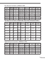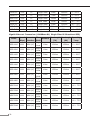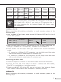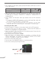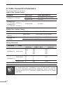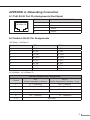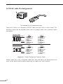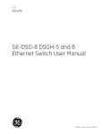
1
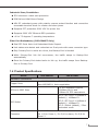
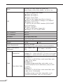
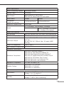
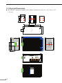
Industrial Gigabit Switch With 4 Port 802.3at PoE+ IGS-504HPT / IGS-624HPT User's Manual Trademarks Copyright © PLANET Technology Corp. 2013. Contents are subject to revision without prior notice. PLANET is a registered trademark of PLANET Technology Corp. All other trademarks belong to their respective owners. Disclaimer PLANET Technology does not warrant that the hardware will work properly in all environments and applications, and makes no warranty and representation, either implied or expressed, with respect to the quality, performance, merchantability, or fitness for a particular purpose. PLANET has made every effort to ensure that this User’s Manual is accurate; PLANET disclaims liability for any inaccuracies or omissions that may have occurred. Information in this User’s Manual is subject to change without notice and does not represent a commitment on the part of PLANET. PLANET assumes no responsibility for any inaccuracies that may be contained in this User’s Manual. PLANET makes no commitment to update or keep the current information in this User’s Manual, and reserves the right to make improvements to this User’s Manual and/or to the products described in this User’s Manual, at any time without notice. If you find information in this manual incorrect, misleading, or incomplete, we would appreciate your comments and suggestions. FCC Warning This equipment has been tested and found to comply with the limits for a Class A digital device, pursuant to Part 15 of the FCC Rules. These limits are designed to provide reasonable protection against harmful interference when the equipment is operated in a commercial environment. This equipment generates, uses, and can radiate radio frequency energy and, if not installed and used in accordance with the Instruction manual, may cause harmful interference to radio communications. Operation of this equipment in a residential area is likely to cause harmful interference in which case the user will be required to correct the interference at his own expense. CE Mark Warning This is a Class A product. In a domestic environment, this product may cause radio interference, in which case the user may be required to take adequate measures. WEEE Warning To avoid the potential effects on the environment and human health as a result of the presence of hazardous substances in electrical and electronic equipment, end users of electrical and electronic equipment should understand the meaning of the crossed-out wheeled bin symbol. Do not dispose of WEEE as unsorted municipal waste; they should be collected separately. Revision PLANET Industrial Gigabit Switch with 4-port 802.3at PoE+ User's Manual For Model: IGS-504HPT / IGS-624HPT Revision: 1.0 (APRIL, 2013) Part No: EM-IGS-504HPT_624HPT_v1.0 (2350-AH0600-000) Table Of Contents 1. Introduction................................................................................................ 5 1.1 Package Contents................................................................................. 5 1.2 How to Use This Manual....................................................................... 5 1.3 Product Features.................................................................................. 6 1.4 Product Specifications........................................................................... 7 1.5 Physical Dimensions.............................................................................10 2. Installation................................................................................................12 2.1 Product Description..............................................................................12 2.1.1 Switch Front Panel.....................................................................13 2.1.2 LED Indicators...........................................................................14 2.1.3 Switch Upper Panel....................................................................15 2.1.4 Wiring the Power Inputs.............................................................16 2.1.5 Wiring the Fault Alarm Contact....................................................17 2.1.6 Cabling......................................................................................17 2.1.7 Redundancy Overview.................................................................23 2.2 Mounting Installation...........................................................................24 2.2.1 DIN-Rail mounting......................................................................24 2.2.2 Wall Mount Plate Mounting..........................................................26 3. Applications................................................................................................27 4. Switch Operation........................................................................................29 4.1 Address Table......................................................................................29 4.2 Learning.............................................................................................29 4.3 Forwarding & Filtering..........................................................................29 4.4 Store-and-Forward...............................................................................29 4.5 Auto-Negotiation.................................................................................30 5. Troubleshooting..........................................................................................31 6. Cable Connection Parameters.......................................................................32 APPENDIX A: Networking Connection.................................................................33 A.1 PoE RJ-45 Port Pin Assignments (End-Span)...........................................33 A.2 Switch’s RJ-45 Pin Assignments.............................................................33 A.3 RJ-45 cable Pin Assignments.................................................................34 1.Introduction Thank you for purchasing PLANET Layer 2 Industrial Gigabit Switch with 4-Port 802.3at PoE+, IGS-504HPT/IGS-624HPT. The descriptions of these models are as follows: IGS-504HPT : Industrial 5-Port Gigabit Switch with 4-Port 802.3at PoE+ (-40~75 degrees C) IGS-624HPT : Industrial 4-Port 10/100/1000T 802.3at PoE + 2-Port 100/1000X SFP Ethernet Switch (-40~75 degrees C) In the following section, the term “Industrial Gigabit PoE+ Switch” means the IGS-504HPT & IGS-624HPT. 1.1 Package Contents Open the box of the Industrial Gigabit PoE+ Switch and carefully unpack it. The box should contain the following items: ll Industrial Gigabit PoE+ Switch x 1 ll User's Manual x 1 ll DIN Rail Kit x 1 ll Wall Mount Kit x 1 If any of these are missing or damaged, please contact your dealer immediately; if possible, retain the carton including the original packing material, and use them again to repack the product in case there is a need to return it to us for repair. 1.2 How to Use This Manual This Industrial Gigabit PoE+ Switch User Manual is structured as follows: Chapter 2 Installation The chapter explains the feature, functionality and the physical installation of the Industrial Gigabit PoE+ Switch. Chapter 3 Application The chapter explains the Industrial Gigabit PoE+ Switch application. Chapter 4 Switch operation The chapter explains the Industrial Gigabit PoE+ Switch transmit operation. 5 Chapter 5 Troubleshooting The chapter explains the troubleshooting of the Industrial Gigabit PoE+ Switch. Chapter 6 Cable Connection Parameters The chapter contains the cable connection parameters of the Industrial Gigabit PoE+ Switch. Appendix A This chapter contains cable information of the Industrial Gigabit PoE+ Switch. 1.3 Product Features Physical Port IGS-504HPT 5-Port 10/100/1000Base-T RJ-45 with IEEE 802.3af/802.3at PoE+ injector IGS-624HPT 4-Port 10/100/1000Base-T RJ-45 with IEEE 802.3af/802.3at PoE+ Injector 2 SFP interfaces, 100/1000Base-X dual mode (DIP switch control) Power over Ethernet Complies with IEEE 802.3af/IEEE 802.3at Power over Ethernet Plus End-Span PSE Up to 4 IEEE 802.3af/802.3at devices powered Supports PoE Power up to 30.8 watts for each PoE ports Provides DC 52V power over RJ-45 Ethernet cable to PD with Ethernet port Auto-detection of IEEE 802.3af/at equipments and protects devices from being damaged by incorrect installation Remote power feeding up to 100m Layer 2 Features Supports Auto-negotiation and 10/100Mbps half/full duplex and 1000Mbps full duplex mode Prevents packet loss with back pressure (Half-Duplex) and IEEE 802.3x PAUSE frame flow control (Full-Duplex) Automatic address learning and address aging 6 Industrial Case/Installation IP30 aluminum metal case protection DIN Rail and Wall Mount Design 48V DC redundant power with polarity reverse protect function and connective removable terminal block for master and slave power Supports EFT protection 6000 VDC for power line Supports 6000 VDC Ethernet ESD protection -40 to 75 degrees C operating temperature Fiber Port Redundancy (IGS-624HPT Only) Dual SFP Ports Auto Link Redundant Mode Support Link status auto-detect and redundant on Dual ports with same connector type Only Primary-Port is active at a time, the Backup-Port is blocked While Primary-Port link fail occurrences, the traffic swaps to Backup-Port automatically Once the Primary-Port status backs to link up, the traffic swaps from BackupPort to Primary-Port 1.4 Product Specifications Model IGS-504HPT IGS-624HPT Hardware Specification Copper Ports 4 x 10/100/1000Base-T RJ-45 TP Auto-MDI/MDI-X, Auto-negotiation SFP/mini-GBIC Slots ― 2 x SFP interfaces Support 1000Base-SX/LX and 100Base-FX SFP transceivers DIP Switch ― DIP-1: SFP Port 5 1000Base-X (default) / 100Base-FX DIP-2: SFP Port 6 1000Base-X (default) / 100Base-FX DIP-3: Switch (default) / Fiber Redundant mode Connector Terminal Block Pin 1/2 for Power 1; Pin 3/4 for alarm; Pin 5/6 for Power 2 7 Alarm Provides one relay output for power fail Alarm Relay current carry ability: 1A @ DC 24V LED 3 x LED for System and Power: Green: DC Power 1 Green: DC Power 2 Green: Power Fault 2 x LED for Per Copper Port (Port-1~Port-4): Green: 1000 LNK/ACT, Orange: 100 LNK/ACT Orange: PoE In-use 1 x LED for Per mini-GBIC interface (IGS-624HPT Port-5 and Port-6): Green: LNK/ACT 4 x LED for PoE Power Usage (W): Orange: 30, 60, 90 and 120W ESD Protection 6KV DC EFT Protection 6KV DC Enclosure IP30 type metal case Installation DIN rail kit and wall mount ear Dimensions 152 x 107 x 72mm Weight 1478g Power Requirement 48V DC, 5A max. Redundant power with polarity reverse protection Power Consumption/ Dissipation 134.1 watts / 451 BTU 135.1 watts / 461 BTU Twisted-Pair 10Base-T : 2-Pair UTP CAT. 3,4,5, up to 100 meter 100Base-TX : 2-Pair UTP CAT. 5, 5e up to 100 meter 1000Base-T : 4-Pair UTP CAT. 5e,6 up to 100 meter Fiber-Optic Cable 1000Base-SX : 50/125μm or 62.5/125μm multi-mode fiber optic cable, up to 550m 1000Base-LX : 9/125μm single-mode fiber optic cable, up to 10/20/30/40/50/70/120 kilometers (vary on SFP module) 100Base-FX : 50/125μm or 62.5/125μm multi-mode fiber optic cable, up to 2 kilometers 9/125μm single-mode fiber optic cable, up to 20/40/60 kilometers (vary on SFP module) Cable 8 1539g Switch Specification Switch Processing Scheme Store-and-Forward Address Table 1K entries Flow Control Back pressure for half duplex IEEE 802.3x Pause Frame for full duplex Switch fabric 10Gbps 12Gbps Throughput (packet per second) 7.44Mpps@64bytes 8.93Mpps@64bytes Maximum Transmit Unit 9216 bytes TP: 10/20Mbps, 100/200Mbps, 2000Mbps Speed SX/LX: 2000Mbps (Full-duplex) FX: 200Mbps (Full-duplex) Power over Ethernet PoE Standard IEEE 802.3af/IEEE 802.3at Power over Ethernet/PSE PoE Power Supply Type End-Span PoE Power Output Per port 52V DC, 275mA. Max. 15.4 watts (IEEE 802.3af) Per port 52V DC, 535mA. Max. 30 watts (IEEE 802.3at) Power Pin Assignment 1/2(+), 3/6(-) Max. number of Class 4 PD 4 Standards Conformance Standards Compliance IEEE IEEE IEEE IEEE IEEE IEEE IEEE 802.3 Ethernet/10Base-T 802.3u Fast Ethernet/100Base-TX 802.3ab Gigabit Ethernet/1000Base-T 802.3z Gigabit Ethernet/1000Base-SX/LX 802.3x Full-Duplex Flow Control 802.3at Power over Ethernet Plus 802.3af Power over Ethernet Regulation Compliance FCC Part 15 Class A, CE Stability Testing IEC60068-2-32 (Free fall) IEC60068-2-27 (Shock) IEC60068-2-6 (Vibration) Environment Temperature Operating: -40~75 degrees C Storage: -40~75 degrees C Humidity Operating: 5~95% (Non-condensing) Storage: 5~95% (Non-condensing) 9 1.5 Physical Dimensions IGS-504HPT Industrial Gigabit PoE+ Switch dimensions (W x D x H): 161 x 107 x 72 mm 40 66 18 50 28 130 23.6 18 66 25.2 V2- V2+ 78 107 PWR1 V1- V1+ 1A@24V -4 3.5 23 36.55 30 152 136 PWR2 Fault Input DC 48V 9.2 60 40 10 R2 72 33.38 60 SFP LNK/ ACT 40 1 2 3 4 30 60 90 120 PoE Power Usage (W) PoE In-Use 1000 100 LNK/ACT P1 P2 FAULT 23 V2- V2+ 107 78 PWR2 Fault Input DC 48V 152 136 72 PWR1 V1- V1+ 1A@24V 66 18 25.2 IGS-624HPT 5 6 100 1000 ON 30 9.2 R2 SFP LNK/ ACT 100 1000 Port 6 Port 5 3 2 1 Fiber Mode Switch Redundant 36.55 50 66 18 IGS-624HPT Industrial Gigabit PoE+ Switch dimensions (W x D x H): 161 x 107 x 72 mm 40 28 130 23.6 3.5 -4 33.38 Industrial 802.3at PoE+ Gigabit Switch 11 2.Installation This section describes the functionalities of the Industrial Gigabit PoE+ Switch’s components and guides how to install it on the desktop. Basic knowledge of networking is assumed. Please read this chapter completely before continuing. 2.1 Product Description High Power PoE for Security and Public Service Applications To fulfill the demand of High Power PoE for network applications with Gigabit speed transmission under wide temperature, the IGS-504HPT and IGS-624HPT provide 4 10/100/1000Mbps ports featuring both IEEE 802.3af and IEEE 802.3at Power over Ethernet Plus (PoE+) that combine up to 30-watt power output and data per port over one Cat.5E / 6 Ethernet cable. With a total of up to 120 watts of PoE output capability, the IGS-504HPT and IGS624HPT are designed specifically to satisfy the growing demand of higher power consuming network PDs (powered devices) such as PTZ (Pan, Tilt & Zoom) speed dome network cameras, multi-channel (802.11a/b/g/n) wireless LAN access points and other PoE network devices by providing double PoE power, rather than the current conventional 802.3af PoE. Environmentally Hardened Design The IGS-504HPT and IGS-624HPT are equipped with rugged IP30 metal case for easy deployment in heavy Industrial demanding environments. With IP30 metal case protection, the IGS-504HPT and IGS-624HPT provide a high level of immunity against electromagnetic interference and heavy electrical surges which are usually found on plant floors or in curb side traffic control cabinets. Being able to operate in the temperature range from -40 to 75 degrees C, the IGS-504HPT and IGS624HPT can be placed in almost any difficult environment. The IGS-504HPT and IGS-624HPT allows either DIN rail or wall mounting for efficient use of cabinet space. Adjustable 6-Port Switch Mode or 4 + 2 Fiber Redundant Mode Via the built-in DIP switch, the IGS-624HPT can be configured as 6-Port Ethernet switch or 4+2 fiber redundant mode. With the 6-port switch mode, the IGS-624HPT can operate in Store-and-Forward mechanism with high performance; on the other hand, when in the 4+2 fiber redundant mode, it provides rapid fiber redundancy of link for highly critical Ethernet applications. The redundant-mode also supports auto-recovering function, if the destination port of a packet is link down, it will forward the packet to the other port of the backup pair. 12 2.1.1 Switch Front Panel 100 1000 100 1 1000 Port 5 ON Port 6 2 Fiber Mode Switch Redundant 3 Figure 2-1 shows the front panels of IGS-504HPT and IGS-624HPT Industrial Gigabit PoE+ Switches. P1 P2 FAULT SFP 6 SFP LNK/ ACT 5 1000 100 LNK/ACT 4 PoE In-Use 3 PoE Power Usage (W) 2 120 90 1 60 Industrial 802.3at PoE+ Gigabit Switch LNK/ ACT 30 IGS-624HPT Figure 2-1: IGS-504HPT & IGS-624HPT Front Panels PoE Power Usage LED The front panel of the Industrial Gigabit PoE+ Switch has four LEDs which indicate “PoE Power Usages (W)” of 30W, 60W, 90W and 120W. With these LED indications, you can monitor current PoE power in use status of Industrial Gigabit PoE+ Switch easily and efficiently. PoE Power Usage (W) 120 90 60 30 13 DIP Switch The front panel of the IGS-624HPT provides one 3-DIP Switch which is for configuring 100 or 1000X fiber support and fiber redundant function. Refer to the table below to know about the 3-DIP switch settings and descriptions: ON 1 2 3 For more information about the fiber redundancy function, please refer to the chapter 2.1.7 Redundancy Overview. OFF (Default) ON Fiber Redundant (DIP 3) Fiber Redundant Switch Port 6 (DIP 2) 1000X 100FX Port 5 (DIP 1) 1000X 100FX 2.1.2 LED Indicators System LED Color Function P1 Green Light: indicates power 1 has power. P2 Green Light: indicates power 2 has power. FAULT Green Light: indicates either power 1 or power 2 has no power. 10/100/1000Base-T Interfaces LED Color Function Light: indicates the Switch is successfully connecting to the network at 1000Mbps. Green Blink: indicates that the Switch is actively sending or receiving data over that port. OFF: indicates that the Switch is inactively sending or receiving data over that port. LNK/ACT Light: indicates the Switch is successfully connecting to the network at 10Mbps or 100Mbps. Orange Blink: indicates that the Switch is actively sending or receiving data over that port. OFF: indicates that the Switch is inactively sending or receiving data over that port. PoE In-Use (Port 1~4) 14 Orange Light: indicates the port is providing 52V DC in-line power. OFF: indicates the connected device is not a PoE Powered Device (PD). 100/1000Base-X SFP Interfaces (IGS-624HPT) LED Color Function Light: indicates the Switch is successfully connecting to the network at 100/1000Mbps. LNK/ACT Green Blink: indicates that the Switch is actively sending or receiving data over that port. OFF: indicates that the Switch is inactively sending or receiving data over that port. Per PoE Power Usage (Unit : Watts) (Lower LED to upper LED) LED Color Function 30 Orange Lights to indicate the system is providing ≥30 Watts PoE power usage 60 Orange Lights to indicate the system is providing ≥60 Watts PoE power usage 90 Orange Lights to indicate the system is providing ≥90 Watts PoE power usage 120 Orange Lights to indicate the system is providing ≥120 Watts PoE power usage 2.1.3 Switch Upper Panel The upper panel of the Industrial Gigabit PoE+ Switch consists of one terminal block connector within two DC power inputs. Figure 2-2 shows the upper panel of the Switch. Figure 2-2 shows upper panel of Industrial Gigabit PoE+ Switch. 1 2 3 4 5 6 Figure 2-2: Industrial Gigabit PoE Switch Upper Panel. 15 2.1.4 Wiring the Power Inputs The 6-contact terminal block connector on the top panel of Industrial Gigabit PoE+ Switch is used for two DC redundant powers input. Please follow the steps below to insert the power wire. 1.Insert positive/negative DC power wires into contacts 1 and 2 for POWER 1, or 5 and 6 for POWER 2. 1 2 3 4 5 6 V1- V1+ V2 - V2+ 2.Tighten the wire-clamp screws for preventing the wires from loosening. 1 2 Power 1 + Note 16 3 Fault 4 5 6 Power 2 + The wire gauge for the terminal block should be in the range between 12 and 24 AWG. 2.1.5 Wiring the Fault Alarm Contact The fault alarm contacts are in the middle of the terminal block connector as the picture shows below. Inserting the wires, the Industrial Gigabit PoE+ Switch will detect the fault status of the power failure, or port link failure (available for managed model) and then forms an open circuit. The following illustration shows an application example for wiring the fault alarm contacts. 1 2 Fault Alarm Contacts Note 3 4 Fault 5 6 The Fault Alarm Contacts are energized (CLOSE) for normal operation and will OPEN when failure occurs 1.The wire gauge for the terminal block should be in the range between 12 ~ 24 AWG. 2.Alarm relay circuit accepts up to 30V, max. 3A currents. 2.1.6 Cabling 10/100/1000Base-T All 10/100/1000Base-T ports come with Auto-Negotiation capability. They automatically support 1000Base-T, 100Base-TX and 10Base-T networks. Users only need to plug a working network device into one of the 10/100/1000Base-T ports, and then turn on the Industrial Gigabit PoE+ Switch. The port will automatically runs in 10Mbps, 20Mbps, 100Mbps or 200Mbps and 1000Mbps or 2000Mbps after the negotiation with the connected device. 100Base-FX/1000Base-SX/LX The IGS-624HPT Industrial Gigabit PoE+ Switch has two SFP interfaces that support 100/1000 dual speed mode (Optional Multi-mode/Single-mode 100BaseFX/1000Base-SX/LX SFP module) through DIP switch setting. Cabling Each 10/100/1000Base-T port uses RJ-45 sockets -- similar to phone jacks -- for 17 connection of unshielded twisted-pair cable (UTP). The IEEE 802.3/802.3u/ 802.3ab Fast/Gigabit Ethernet standard requires Category 5 UTP for 100Mbps 100Base-TX. 10Base-T networks can use Cat.3, 4, 5 or 1000Base-T uses 5/5e/6 UTP (see table below). Maximum distance is 100 meters (328 feet). The 100Base-FX/1000BaseSX/LX SFP slot is used as LC connector with optional SFP module. Please see table below and know more about the cable’s specification. Port Type Cable Type Connector 10Base-T Cat 3, 4, 5, 2-pair RJ-45 100Base-TX Cat.5 UTP, 2-pair RJ-45 1000Base-T Cat.5/5e/6 UTP, 4-pair RJ-45 100Base-FX 50/125µm or 62.5/125µm multi-mode 9/125µm single-mode LC (Multi/Single mode) 1000Base-SX/ 50/125µm or 62.5/125µm multi-mode LX 9/125µm single-mode LC (Multi/Single mode) Any Ethernet devices like hubs/PCs can be connected to the Industrial Gigabit PoE+ Switch by using straight-through wires. The four 10/100/1000Mbps ports are autoMDI/MDI-X and can be used on straight-through or crossover cable. 2.1.6.1 Installing the SFP transceiver The sections describe how to insert an SFP transceiver into the IGS-624HPT SFP slot. The SFP transceivers are hot-pluggable and hot-swappable. You can plug-in and out the transceiver to/from any SFP port without having to power down the Industrial Gigabit PoE+ Switch as the Figure 2-3 appears. MGB / MFB Series Transceiver Figure 2-3: Plug-in the SFP transceiver Approved PLANET SFP Transceivers PLANET Industrial Gigabit PoE+ Switch supports both Single mode and Multi-mode SFP transceivers. The following list of approved PLANET SFP transceivers is correct at the time of publication: 18 Fast Ethernet Transceiver (100Base-X SFP) Model Speed (Mbps) Connector Interface Fiber Mode Distance Wavelength (nm) Operating Temp. MFB-FX 100 LC Multi Mode 2km 1310nm 0 ~ 60°C MFB-F20 100 LC Single Mode 20km 1310nm 0 ~ 60°C MFB-F40 100 LC Single Mode 40km 1310nm 0 ~ 60°C MFB-F60 100 LC Single Mode 60km 1310nm 0 ~ 60°C MFB-F120 100 LC Single Mode 120km 1550nm 0 ~ 60°C MFB-TFX 100 LC Multi Mode 2km 1310nm -40 ~ 75°C MFB-TF20 100 LC Single Mode 20km 1550nm -40 ~ 75°C Fast Ethernet Transceiver (100Base-BX, Single Fiber Bi-Directional SFP) Model Speed Connector Fiber Wavelength Wavelength Operating Distance (Mbps) Interface Mode (TX) (RX) Temp. MFB-FA20 100 WDM (LC) Single Mode 20km 1310nm 1550nm 0 ~ 60°C MFB-FB20 100 WDM (LC) Single Mode 20km 1550nm 1310nm 0 ~ 60°C MFB-TFA20 100 WDM (LC) Single Mode 20km 1310nm 1550nm -40 ~ 75°C MFB-TFB20 100 WDM (LC) Single Mode 20km 1550nm 1310nm -40 ~ 75°C MFB-TFA40 100 WDM (LC) Single Mode 40km 1310nm 1550nm -40 ~ 75°C MFB-TFB40 100 WDM (LC) Single Mode 40km 1550nm 1310nm -40 ~ 75°C Gigabit Ethernet Transceiver (1000Base-X SFP) Model Speed (Mbps) Connector Interface MGB-GT 1000 MGB-SX 1000 MGB-SX2 1000 LC MGB-LX 1000 LC MGB-L30 1000 LC MGB-L40 1000 LC Wavelength (nm) Operating Temp. 100m -- 0 ~ 60°C 550m 850nm 0 ~ 60°C Multi Mode 2km 1310nm 0 ~ 60°C Single Mode 10km 1310nm 0 ~ 60°C Single Mode 30km 1310nm 0 ~ 60°C Single Mode 40km 1550nm 0 ~ 60°C Fiber Mode Distance Copper -- LC Multi Mode 19 MGB-L50 1000 LC Single Mode 50km 1550nm 0 ~ 60°C MGB-L70 1000 LC Single Mode 70km 1550nm 0 ~ 60°C MGB-L120 1000 LC Single Mode 120km 1550nm 0 ~ 60°C MGB-TSX 1000 LC Multi Mode 550m 850nm -40 ~ 75°C MGB-TLX 1000 LC Single Mode 10km 1310nm -40 ~ 75°C MGB-TL30 1000 LC Single Mode 30km 1310nm -40 ~ 75°C MGB-TL50 1000 LC Single Mode 50km 1550nm -40 ~ 75°C Gigabit Ethernet Transceiver (1000Base-BX, Single Fiber Bi-Directional SFP) Model Speed Connector Fiber Wavelength Wavelength Operating Distance (Mbps) Interface Mode (TX) (RX) Temp. MGB-LA10 1000 WDM (LC) Single Mode 10km 1310nm 1550nm 0 ~ 60°C MGB-LB10 1000 WDM (LC) Single Mode 10km 1550nm 1310nm 0 ~ 60°C MGB-LA20 1000 WDM (LC) Single Mode 20km 1310nm 1550nm 0 ~ 60°C MGB-LB20 1000 WDM (LC) Single Mode 20km 1550nm 1310nm 0 ~ 60°C MGB-LA40 1000 WDM (LC) Single Mode 40km 1310nm 1550nm 0 ~ 60°C MGB-LB40 1000 WDM (LC) Single Mode 40km 1550nm 1310nm 0 ~ 60°C MGB-LA60 1000 WDM (LC) Single Mode 60km 1310nm 1550nm 0 ~ 60°C MGB-LB60 1000 WDM (LC) Single Mode 60km 1550nm 1310nm 0 ~ 60°C MGB-TLA10 1000 WDM (LC) Single Mode 10km 1310nm 1550nm -40 ~ 75°C MGB-TLB10 1000 WDM (LC) Single Mode 10km 1550nm 1310nm -40 ~ 75°C MGB-TLA20 1000 WDM (LC) Single Mode 20km 1310nm 1550nm -40 ~ 75°C MGB-TLB20 1000 WDM (LC) Single Mode 20km 1550nm 1310nm -40 ~ 75°C MGB-TLA40 1000 WDM (LC) Single Mode 40km 1310nm 1550nm -40 ~ 75°C 20 MGB-TLB40 1000 WDM (LC) Single Mode 40km 1550nm 1310nm -40 ~ 75°C MGB-TLA60 1000 WDM (LC) Single Mode 60km 1310nm 1550nm -40 ~ 75°C MGB-TLB60 1000 WDM (LC) Single Mode 60km 1550nm 1310nm -40 ~ 75°C Note It is recommended to use PLANET SFP transceivers on the Industrial Gigabit PoE+ Switch. If you insert an SFP transceiver that is not in the supported list, the Industrial Gigabit PoE+ Switch might not recognize it. 1000Base-SX/LX: Before connecting with switches, workstation or media converter, please do the following steps: 1.With 1000Base-X Fiber Speed, please set the DIP Switch of SFP Port 5 or Port 6 to the “OFF” position. OFF ON Port 6 (DIP 2) 1000X 100FX Port 5 (DIP 1) 1000X 100FX 2.Make sure both sides of the SFP transceivers are with the same media type, for example: 1000Base-SX to 1000Base-SX, 1000Base-LX to 1000Base-LX. 3.Check whether the fiber-optic cable type matches with the SFP transceiver model. To connect to 1000Base-SX SFP transceiver, use the Multi-mode fiber cable with one side being the male duplex LC connector type. To connect to 1000Base-LX SFP transceiver, use the Single-mode fiber cable with one side being the male duplex LC connector type. Connecting the fiber cable 1.Insert the duplex LC connector on the network cable into the SFP transceiver. 2.Connect the other end of the cable to a device – switches with SFP installed, fiber NIC on a workstation or a media converter. 3.Check the LNK/ACT LED of the SFP slot on the front of the Industrial Gigabit PoE+ Switch. Ensure that the SFP transceiver is operating correctly. 100Base-FX: Before connecting with switches, workstation or media converter, please do the following steps: 21 1.With 100Base-FX Fiber Speed, please set the DIP Switch of SFP Port 5 or Port 6 to the “ON” position. OFF ON Port 6 (DIP 2) 1000X 100FX Port 5 (DIP 1) 1000X 100FX 2.Make sure both sides of the SFP transceivers are with the same media type or WDM pair, for example, 100Base-FX to 100Base-FX, 100Base-BX20-U to 100Base-BX20-D. 3.Check whether the fiber-optic cable type matches with the SFP transceiver model. To connect to MFB-FX SFP transceiver, use the multi-mode fiber cable with one side being the male duplex LC connector type. To connect to MFB-F20/F40/F60/FA20/FB20 SFP transceiver, use the singlemode fiber cable with one side being the male duplex LC connector type. Connecting the fiber cable 1.Insert the duplex LC connector on the network cable into the SFP transceiver. 2.Connect the other end of the cable to a device – switches with SFP installed, to fiber NIC on a workstation or a media converter. 3.Check the LNK/ACT LED of the SFP slot of the switch/converter. Ensure that the SFP transceiver is operating correctly. 2.1.6.2 Remove the Transceiver Module 1.Make sure there is no network activity by consulting or checking with the network administrator. Or through the management interface of the switch/ converter (if available) to disable the port in advance. 2.Remove the Fiber Optic Cable gently. 3.Turn the latch of the MGB/MFB module to a horizontal position. 4.Pull out the module gently through the latch. MGB / MFB Series Transceiver 2 1 Figure 2-4: Pulling out from the transceiver 22 Note Never pull out the module without pulling the latch or the push bolts on the module. Directly pulling out the module with violence could damage the module and the SFP module slot of the Industrial Gigabit Ethernet Switch. 2.1.7 Redundancy Overview The IGS-624HPT Industrial Gigabit PoE+ Switch provides rapid fiber redundancy of link for highly critical Ethernet applications. The redundant-mode supports auto-recover function. If the destination port of a packet is link down, it forwards the packet to the other port of the backup pair. The following figure shows the redundant function. Redundancy Main Primary Backup < Primary Port > Link Status : Up Traffic Flow : Forwarding < Backup Port > Link Status : Down Traffic Flow : Blocking Redundancy Main Primary < Primary Port > Link Status : Down Traffic Flow : N/A Backup < Backup Port > Link Status : Up Traffic Flow : Forwarding Traffic is changed from Primary -Port to Backup-Port Figure 2-5: Redundancy Behavior Topology ll Link status auto detect and redundant on Dual ports with same connector type. ll Only Primary-Port is active at a time, the Backup-Port is blocked. ll When Primary-Port link failure occurs, the traffic swaps to Backup-Port automatically. ll Once the Primary-Port status is back to link up, the traffic will swap from Backup-Port to Primary-Port. 23 2.2 Mounting Installation This section describes how to install the Industrial Gigabit PoE+ Switch and make connections to it. Please read the following topics and perform the procedures in the order being presented. Note In the installation steps below, this Manual uses IGS-801 (PLANET 8 Port Industrial Gigabit Switch) as the example. However, the steps for PLANET Industrial Gigabit PoE+ Switch are similar. 2.2.1 DIN-Rail mounting The DIN-Rail is screwed on the Industrial Gigabit Ethernet Switch when out of factory. When needed to replace the wall mount application with the DIN-Rail application on Industrial Gigabit Ethernet Switch, please refer to the following figures to screw the DIN-Rail on the Industrial Gigabit Ethernet Switch. To hang the Industrial Gigabit Ethernet Switch, follow the steps below: Step 1: Screw the DIN-Rail on the Industrial Gigabit Ethernet Switch. 24 1 2 Step 2: Lightly insert the bottom of the switch into the track Step 3: Check if the DIN-Rail is tightly on the track. Step 4: Please refer to the following procedures to remove the Industrial Gigabit Ethernet Switch from the track. 25 1 2 Step 5: Lightly pull out the bottom of the switch for removing it from the track. 2.2.2 Wall Mount Plate Mounting To install the Industrial Gigabit Ethernet Switch on the wall, please follow the instructions described below. Step 1: To remove the DIN-Rail from the Industrial Gigabit Ethernet Switch, loose the screws to remove the DIN-Rail. Step 2: Place the wall mount plate on the rear panel of the Industrial Gigabit Ethernet Switch. Step 3: Use the screws to screw the wall mount plate on the Industrial Gigabit Ethernet Switch. Step 4: Use the hook holes at the corners of the wall mount plate to hang the Industrial Gigabit Ethernet Switch on the wall. Step 5: To remove the wall mount plate, reverse the steps above. 26 3.Applications In this paragraph, we will describe how to install Industrial Gigabit PoE+ Switch and the installation points. Industrial Operating Environment 550m / 10km / 120km Control Center PoE+ PTZ Speed Dome Fiber Switch PoE PoE 1000 1000 1000Base-SX/LX Fiber-optic PoE 1000Base-T UTP with PoE DC Power Line (DC) 100m DC Data Power DC 48V IGS-624HPT Harsh Climate PoE IP Camera Weather Station Desert PoE IP Camera PoE PoE PoE PoE IGS-624HPT IGS-624HPT PoE IP Camera 1000 1000 70km 40km PoE IP Camera Fiber Switch PoE 1000 PoE 120km Data Center IGS-624HPT Steel Factory 1000 1000Base-SX/LX Fiber-optic PoE 1000Base-T UTP with PoE 27 Installation Steps Step 1: Unpack the Industrial Gigabit PoE+ Switch. Step 2: Check the DIN-Rail is screwed on the Industrial Gigabit PoE+ Switch. (Please refer to DIN-Rail Mounting section for DIN-Rail installation, if the DIN-Rail is not screwed on the Industrial switch). If you want to wallmount the Industrial Gigabit Ethernet Switch, please refer to Wall Mount Plate Mounting section for wall-mount plate installation. Step 3: To hang the Industrial Gigabit PoE+ Switch on the DIN-Rail track or wall, please refer to the Mounting Installation section. Step 4: Power on the Industrial Gigabit PoE+ Switch. (Please refer to the Wiring of the Power Inputs section for power input) The power LED on the Industrial Gigabit PoE+ Switch will light up. Please refer to the LED Indicators section for the functions of LED lights. Step 5: Prepare the twisted-pair, straight through Category 5 cable for Ethernet connection. Step 6: Insert one side of Category 5 cable into the Industrial Gigabit PoE+ Switch Ethernet port (RJ-45 port) and the other side of category 5 cable to the network devices’ Ethernet port (RJ-45 port), eg. switch, PC or Server. The UTP port (RJ-45) LED on the Industrial Gigabit PoE+ Switch will light up when the cable is connected with the network device. Please refer to the LED Indicators section for the functions of LED lights. Step 7: When all connections are set and all LED lights show normally, the installation is complete. Note 28 Be sure the connected network devices support MDI/MDI-X. If it does not support, then use the crossover category 5 Cable. 4.Switch Operation 4.1 Address Table The Industrial Gigabit PoE+ Switch is implemented with an address table. This address table is composed of many entries. Each entry is used to store the address information of some nodes in network, including MAC address, port no, etc. This information comes from the learning process of Industrial Gigabit PoE+ Switch. 4.2 Learning When one packet comes from any port, the Industrial Gigabit PoE+ Switch will record the source address, port number and the other related information in address table. This information will be used to decide either forwarding or filtering for future packets. 4.3 Forwarding & Filtering When one packet comes from some ports of the Industrial Gigabit PoE+ Switch, it will also check the destination address besides the source address learning. The Industrial Gigabit PoE+ Switch will look up the address table for the destination address. If not found, this packet will be forwarded to all the other ports except the port which this packet comes in. And these ports will transmit this packet to the network it connected. If found, and the destination address is located at a different port from this packet that comes in, the Industrial Gigabit PoE+ Switch will forward this packet to the port where this destination address is located according to the information from address table. But, if the destination address is located at the same port with this packet that comes in, then this packet will be filtered; thereby increasing the network throughput and availability. 4.4 Store-and-Forward Store-and-Forward is one type of packet-forwarding techniques. Forward Industrial Gigabit PoE+ Switch stores the incoming frame buffer and does the complete error checking before transmission. error packets occurs. It is the best choice when a network needs stability. A Store-and in an internal Therefore, no efficiency and The Industrial Gigabit PoE+ Switch scans the destination address from the packetheader, searches the routing table provided for the incoming port and forwards the packet, only if required. The fast forwarding makes the switch attractive for connecting servers directly to the network, thereby increasing throughput and availability. However, the switch is most commonly used to segment existing hubs, 29 which nearly always improves the overall performances. An Ethernet Switching can be easily configured in any Ethernet network environment to significantly boost bandwidth using the conventional cabling and adapters. Due to the learning function of the Industrial Gigabit PoE+ Switch, the source address and corresponding port number of each incoming and outgoing packet are stored in a routing table. This information is subsequently used to filter packets whose destination address is on the same segment as the source address. This confines network traffic to its respective domain and reduces the overall load on the network. The Industrial Gigabit PoE+ Switch performs “Store and Forward”; therefore, no error packets occur. More reliably, it reduces the re-transmission rate. No packet loss will occur. 4.5 Auto-Negotiation The STP ports on the Industrial Gigabit PoE+ Switch have built-in “Autonegotiation”. This technology automatically sets the best possible bandwidth when a connection is established with another network device (usually at Power On or Reset). This is done by detecting the modes and speeds at the second of both devices that are connected and capable of. Both 10Base-T and 100Base-TX devices can connect with the port in either Half- or Full-Duplex mode. 1000Base-T can be only connected in Full-duplex mode. 30 5.Troubleshooting This chapter contains information to help you solve issues. If the Industrial Gigabit PoE+ Switch is not functioning properly, make sure the Industrial Gigabit PoE+ Switch was set up according to instructions in this manual. The Link LED does not light up Solution: Check the cable connection and also try to swap one new cable. Performance is bad Solution: Check the speed duplex mode of the partner device. The Industrial Gigabit PoE+ Switch is run at Auto-negotiation mode and if the partner is set to half duplex, then the performance will be poor. 1000Base-T port link LED lights up, but the traffic is irregular Solution: Check that the attached device is not set to full duplex. Some devices use a physical or software switch to change duplex modes. Auto-negotiation may not recognize this type of full-duplex setting. Why the Industrial Gigabit PoE+ Switch doesn’t connect to the network Solution: Check per port LED on the Industrial Gigabit PoE+ Switch. Try another port on the Industrial Gigabit PoE+ Switch. Make sure the cable is installed properly. Make sure the cable is the right type. Turn off the power. After a while, turn on the power again. Why after my PoE PD device is connected to IGS-504HPT/IGS-624HPT, it cannot power on? Solution: Please check the cable type of the connection from IGS-504HPT/IGS-624HPT (port 1 to port 4) to the other end. The cable should be an 8-wire UTP, Category 5 or above, EIA568 cable within 100 meters. A cable with only 4-wire, short loop or over 100 meters, all will affect the power supply. Please check and assure the device is fully complied with IEEE 802.3af/IEEE 802.3at standard. Can I install MGB-SX or other non wide temperature SFP module into SFP slot of Industrial Gigabit PoE+ Switch? Solution: Yes, you can. However, since the MGB-SX and other non wide temperature SFP modules cannot operate under -40 degrees C, it must be brought to attention. Please pay attention to this point. 31 6.Cable Connection Parameters The wiring details are as below: 100FX Fiber Optical Cables: Standard 100Base-FX (1310nm) 100Base-BX-U (TX :1310/RX :1550nm) 100Base-BX-D (TX :1550/RX :1310nm) Fiber Type Cable Specification Multi-mode 50/125μm or 62.5/125μm Single-mode 9/125μm Single-mode 9/125μm 1000X Fiber Optical Cables: Standard Fiber Type Cable Specification 1000Base-SX (850nm) Multi-mode 50/125μm or 62.5/125μm Multi-mode 50/125μm or 62.5/125μm Single-mode 9/125μm 1000Base-LX (1310nm) Wiring Distances: Standard 1000Base-SX 1000Base-LX 1000Base-ZX Note 32 Fiber Diameter (micron) Modal Bandwidth (MHz * km) Max. Distance (meters) Multi-mode 62.5 62.5 50 50 100 200 400 500 220 275 500 550 Multi-mode 62.5 50 50 5 4 5 550 Single-mode 9 N/A 5000 Single-mode 9 N/A ~70,000 The Single-mode port (1000Base-LX port) of IGS-624HPT complies with LX 5 kilometers and provides additional margin allowing for 10/20/30/40/50/70/120 kilometers Gigabit Ethernet link on single mode fiber. APPENDIX A: Networking Connection A.1 PoE RJ-45 Port Pin Assignments (End-Span) 12345678 PIN NO RJ-45 POWER ASSIGNMENT 1 • Power + 2 • Power + 3 • Power - 4 • Power - A.2 Switch’s RJ-45 Pin Assignments 1000Mbps, 1000Base-T Contact MDI MDI-X 1 BI_DA+ BI_DB+ 2 BI_DA- BI_DB- 3 BI_DB+ BI_DA+ 4 BI_DC+ BI_DD+ 5 BI_DC- BI_DD- 6 BI_DB- BI_DA- 7 BI_DD+ BI_DC+ 8 BI_DD- BI_DC- 10/100Mbps, 10/100Base-TX RJ-45 Connector pin assignment Contact MDI Media Dependant Interface MDI-X Media Dependant Interface -Cross 1 Tx + (transmit) Rx + (receive) 2 Tx - (transmit) Rx - (receive) 3 Rx + (receive) Tx + (transmit) 4, 5 6 7, 8 Not used Rx - (receive) Tx - (transmit) Not used 33 A.3 RJ-45 cable Pin Assignments The standard RJ-45 receptacle/connector There are 8 wires on a standard UTP/STP cable and each wire is color-coded. The following shows the pin allocation and color of straight cable, and crossover cable connection: Straight Cable 1 2 3 4 5 6 7 8 SIDE 1 1 2 3 4 5 6 7 8 SIDE 2 SIDE 1 1 = White/Orange 2 = Orange 3 = White/Green 4 = Blue 5 = White/Blue 6 = Green 7 = White/Brown 8 = Brown SIDE 2 1 = White/Orange 2 = Orange 3 = White/Green 4 = Blue 5 = White/Blue 6 = Green 7 = White/Brown 8 = Brown SIDE 1 1 = White/Orange 2 = Orange 3 = White/Green 4 = Blue 5 = White/Blue 6 = Green 7 = White/Brown 8 = Brown SIDE 2 1 = White/Green 2 = Green 3 = White/Orange 4 = Blue 5 = White/Blue 6 = Orange 7 = White/Brown 8 = Brown Cross Over Cable 1 2 3 4 5 6 7 8 SIDE 1 1 2 3 4 5 6 7 8 SIDE 2 Figure A-1: Straight-Through and Crossover Cable Please make sure your connected cables are with the same pin assignment and color as the above picture before deploying the cables into your network. 34 EC Declaration of Conformity For the following equipment: *Type of Product : *Model Number : * Produced by: Manufacturer Name Manufacturer Address Industrial 4-Port 10/100/1000T 802.3at PoE + 2-Port 100/1000X SFP Ethernet Switch Industrial 5-Port Gigabit Switch w/ 4-Port 802.3at PoE+ IGS-624HPT, IGS-504HPT : Planet Technology Corp. : 10F., No.96, Minquan Rd., Xindian Dist., New Taipei City 231, Taiwan (R.O.C.) is herewith confirmed to comply with the requirements set out in the Council Directive on the Approximation of the Laws of the Member States relating to Electromagnetic Compatibility Directive on (2004/108/EC). For the evaluation regarding the EMC, the following standards were applied: EN 55022 EN 61000-3-2 EN 61000-3-3 EN 55024 EN 61000-4-2 EN 61000-4-3 EN 61000-4-4 EN 61000-4-5 EN 61000-4-6 EN 61000-4-8 EN 61000-4-11 (Class A: 2010) (2006 + A1:2009 + A2:2009) (2008) (2010) (2009) (2006 + A1:2008 + A2 :2010) (2004 + A1:2010) (2006) (2009) (2010) (2004) Responsible for marking this declaration if the: Manufacturer Authorized representative established within the EU Authorized representative established within the EU (if applicable): Company Name: Planet Technology Corp. Company Address: 10F., No.96, Minquan Rd., Xindian Dist., New Taipei City 231, Taiwan (R.O.C.) Person responsible for making this declaration Name, Surname Kent Kang Position: Product Manager Taiwan Place 3, June, 2013 Date Legal Signature PLANET TECHNOLOGY CORPORATION e-mail: [email protected] http://www.planet.com.tw 10F., No.96, Minquan Rd., Xindian Dist., New Taipei City, Taiwan, R.O.C. Tel:886-2-2219-9518 Fax:886-2-2219-9528 This page is intentionally left blank