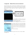
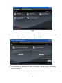
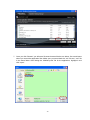
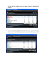
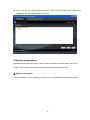
1
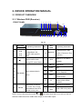
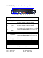
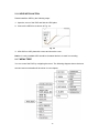
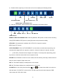
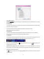
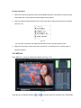
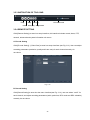
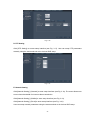
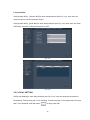
4CH 2.4GHz Digital Wireless H.264 DVR System with Network function USER MANUAL (PLEASE READ BEFORE USE) Thank you for purchasing our product, we will provide you the best service. The specification maybe concludes the insufficient point on technology or the function is not the same with its operation, the wrong spelling word. We sincerely hope you can reflect your advice or opinion to us, we will make the improvement on the product according to your valued advices. The contents of this Manual are subject to change without notice. CONTENT 1 INTRODUCTION............................................................................................................ 1 1.1 Safety precautions ..................................................................................................... 1 1.2 ENTIRONMENT ADAPTABILITY .............................................................................. 1 1.3 MAIN FEATURE ........................................................................................................ 2 1.4 PRODUCT FEATURES ............................................................................................. 2 1.5 PRODUCT SPECIFICATION PARAMETERS ........................................................... 3 1.6 Packaging and Accessories ....................................................................................... 5 2. DEVICE OPERATION MANUAL .................................................................................. 6 2.1 PRODUCT OVERVIEW ............................................................................................. 6 2.1.1 FRONT PANEL .............................................................................................................. 6 2.1.2 REAR PANEL (Details please refer to the real product) ................................................ 7 2.1.3 REMOTE CONTROL ..................................................................................................... 8 2.1.4 Camera Control Elements ........................................................................................ 9 2.1.5 MOUSE OPERATION.................................................................................................. 11 2.1.6 HDD INSTALLATION................................................................................................... 12 2.1.7 MENU TREE ................................................................................................................ 12 2.2 SYSTEM OPERATION ............................................................................................ 13 2.2.1 USER LOGIN ............................................................................................................... 13 2.2.2 SYSTEM SETTINGS ................................................................................................... 15 2.2.3 RECORD SEARCH...................................................................................................... 16 2.2.4 BACKUP ...................................................................................................................... 19 2.2.5 PLAYBACK WITH BACK-UP VIDEO DATA ON PC .................................................... 19 2.2.6 PTZ Control.................................................................................................................. 21 2.2.7 RECORD ..................................................................................................................... 22 2.2.8 VIDEO.......................................................................................................................... 24 2.2.9 SYSTEM ...................................................................................................................... 26 2.2.10 NETWORK................................................................................................................. 30 2.2.11 ALARM SETUP.......................................................................................................... 35 2.2.12 PTZ ............................................................................................................................ 37 3. IE OPERATION .......................................................................................................... 37 3.1 FEATURE ................................................................................................................ 37 3.2 NETWORK SECURITY SETTING ........................................................................... 38 3.3 CONNECTION SETTING ........................................................................................ 39 3.4 CONRTOL DOWNLOAD AND INSTALLATION ...................................................... 41 3.5 OPERATION INTERFACE....................................................................................... 42 3.5.1 LIVE ............................................................................................................................. 42 3.5.2 REPLAY....................................................................................................................... 43 3.5.3 INSTRUCTION OF TOOL BAR.................................................................................... 45 3.5.4 REMOTE SETTING ..................................................................................................... 45 3.5.5 Local Setting ................................................................................................................ 49 3.5.6 Logout .......................................................................................................................... 50 4. FAQ ............................................................................................................................ 51 5.Appendix:Mobile Phone Access Instruction……………………………….……….54 1 INTRODUCTION 1.1 Safety precautions 1) To reduce risk of electric shock, do not disassemble this device. 2) Use only the supplied power supplies. 3) Defective parts must be replaced by original spare parts only. 4) If you spill liquid on it, unplug the device from the AC outlet to prevent possible fire or shock hazard and consult authorized service personnel. 5) When cleaning the device, turn it off first, use a clean soft cloth moistened with a little bit of water to clean it. 6) Do not apply pressure to it or drop it. 7) If does not work correctly, return it to the dealer where it was purchased. Do not dismantle it by yourself. 8) Do not use the device close to heater, refrigerator or stove. 9) When device is in use, do not direct the lens toward any bright light. Power cord operated equipment or accessories connected to the device should bear the CE certification mark and should not be modified in any way that might defeat the safety features, the device meets all European standards for EMC, safety and radio Frequency, however interference form other RF Transmitters may occur .the range of the device is at least 100meters in an open air situation, however indoor the range is highly influenced by construction materials applied within the house. NO guarantee or liability will be accepted for any damage caused due to incorrect use of the device supplied, other than indicated in this owner’s manual. 1.2 ENTIRONMENT ADAPTABILITY For your own safety and for a longer product service life, please pay attention to the following points: 1) When installing device, please comply with all the safety criteria. 2) Power and electricity safety tips: Do not touch the power and DVR with wet hands. Do not spill liquid on the DVR. Do not put any objects on the DVR. 1 Please use a soft dry cloth to clean DVR, do not use any chemicals. Please note that the device will have voltage before startup if it is connected to a power source. Please unplug power cord from its power source if the device will not be used for a long time. 1.3 MAIN FEATURE This kit is a complete 2.4GHz digital wireless H.264 DVR security system that contains a multi-channel network DVR and a number of cameras. It uses an advanced digital modulation design, and its wireless camera is with 24 IR sensors for day and night use. The kit was designed to be compatible with wired and wireless camera to use. It's an ideal do-it-yourself (DIY) protection and security solution for your home, business office, stores, retail operations, wherever security is a concern, this all-in-one system offers a 300-foot operating range(in open site), can be installed easily in minutes, and requires no monitoring services or fees. This DVR system also uses graphical interface, easy to use and supports 3G mobile phone surveillance and E-mail function. Its continuous recording time can up to 40 days with 1TB HD @ 25fps and backup file supports windows media player. 1.4 PRODUCT FEATURES 4 channel system16QAM/QPSK/BPSK digital modulation, 4 channels wireless or 2 channels wired optional H.264 DVR system with network function Graphical interface, easy to use Long recording time up to 40 days with 1TB HD @ 25fps Built in removable HDD rack Remote control or manual or USB mouse operating Camera has 24 IR LEDs for night vision Support dual coding stream Support network file share function Support Four channel simultaneous playback Support 3G mobile phone surveillance and E-mail function. Transmission distance up to 100m (line of sight) 2 1.5 PRODUCT SPECIFICATION PARAMETERS Item System Language Multi-language GUI OSD Menu password user password, administrator password Video input Video Video output Video display Video standard Picture Wireless DVR Alarm Connector Software others CH1~CH4 Antenna Receiver Wireless Camera, CH2 and CH4 input cable or wireless switch select. 1 BNC composite video output 1.0Vp-p, impedance 75Ω, 1 VGA output 1, 4, PIP(1*1), PIP(1*2) PAL: 25f/s, CCIR625line, 50scene NTSC: 30f/s, CCIR525line, 60scene Video Format H.264 compression Picture resolution CIF/HD1/D1 Video code rate CIF: 100fps/4ch;HD1:100fps/4ch;D1:50fps/4ch; Data storage One SATA HDD storage, up to 1.0TB Receiver Frequency 2.400GHz~2.4835GHz Transmission channels auto selection Receiver sensitivity -80dBm Min. Video Output Level 1±0.2Vp-p @75 ohm Video Format MPEG 4 compression Video bit rate up to 12 Mbps Random ID code up to 4 million sets Antenna Omni-directional Operational range Up to 100 meters (line of sight) Alarm input 4 alarm inputs Alarm output 1 alarm output Serial interface Supports 1 RS485 Network interface RJ45,10M/100M proceeding and store DVR Receiver Support USB firmware upgrade voltage input AC:110~240V Voltage output DC: 12V/5A Dimensions (mm) 315(W) x 224 (D) x 52 (H) mm Working temperature -10℃ to 50℃ 3 ITEM Transmitter Transmit Frequency 2.400 ~ 2.4835GHz Video bit rate up to 12 Mbps Random ID code up to 4 million sets Output power (max) 1W/FCC or100mW /CE Antenna input port Type SMA jack Antenna Omni-directional Effective Night Vision Range 7 meter (24 IR LED on) Image sensor (Optional) 1/3″ Color CCD or 1/4″ Color CMOS Camera Resolution(Optional) 420 TV Line or 480 TV Line or 520 TV Line or 380 TV Line Picture element 512*582 (PAL), 512*492 (NTSC) Min. illumination 0 LUX at night(LED ON) Operational range Up to 100 meters (line of sight) Digital Modulation 16QAM/QPSK/BPSK Wireless Video Format MPEG 4 compression Video bit rate up to 12 Mbps Video resolution 720 x 480 @ 30 fps (NTSC) or 768 x 576 @ 25 fps (PAL) Video Format NTSC / PAL optional Power supply 12VDC/1A (Transmitter) Dimensions (mm) Length 155 * Width 70 * High 60 (Transmitter) 4 1.6 Package Contents: Wireless DVR 1PC Wireless Camera 4PCS 2.4GHz Antenna 8PCS Adapter Driver CD w/user manual 1PC Remote control 1PC Power cord 1PC Mouse 1PC 5PCS Note: Hard disk drive (optional, depends on the model) (if you would like to use your own Hard disk drive, please see Appendix 3 for the list of compatible HDDs) 5 2. DEVICE OPERATION MANUAL 2.1 PRODUCT OVERVIEW 2.1.1 Wireless DVR (Receiver) FRONT PANEL 1 2 3 4 5 12 17 6 7 8 14 16 15 18 19 9 10 11 13 Fig. 2-1 No. Key name 4ch 1 CH1 2 CH2 3 CH3 4 CH4 5 Operating instruction No. 6 MENU/ESC 4 Channels preview / switch control mode during PTZ control frame 7 REW 8 【►/║】 9 STOP Stop Move selected item in 10 FWD Fast playback, 2×, 4× and 8× playback menu 11 REC Start manual record/stop manual record 【▲▼◄►】 14 15 16 ENTER Operating instruction name Corresponding channel is magnified in full screen under preview state 12 13 Key This button is used as the “enter” key in most circumstances and PTZ control on live view NOTE: On live view press the button or Access tool bar / Hide tool bar / Exit menu / Exit sub menu Rewind, 2×, 4× and 8× playback Play/Pause 17 IR Infrared receiving window of the remote controller 18 POWER Red LED is for record 19 HDD Green LED is for power ten times when there is no tool bar, this will switch the main menu from CVBS video output to VGA video output. 6 2.1.2 REAR PANEL (Details please refer to the real product) 1 3 6 2 7 8 9 10 11 12 4 13 14 5 15 16 17 18 Fig. 2-2 Item Physical connector 1 Antenna SMA input Ports 2 PAIR1 CH1 Button for Transmitter and Receiver Link pairing. 3 PAIR2 CH2 Button for Transmitter and Receiver Link pairing. 4 PAIR3 CH3 Button for Transmitter and Receiver Link pairing. 5 PAIR4 CH4 Button for Transmitter and Receiver Link pairing. 6 USB port 7 8 9 CH2 Input select Switch VGA output CH4 Input Select Switch Connector description Can be connected 4 pieces 2.4GHz Antennas Backup video recordings and connect the mouse via the USB port CH2 input can also be preset wired mode (cable) (normal use is wireless mode (RF)) by sliding Input Select Switch when CH2 input port was connected a wired camera. For connecting a VGA monitor CH4 input can also be preset wired mode (cable) (normal use is wireless mode (RF)) by sliding Input Select Switch when CH4 input port was connected a wired camera. 10 CH2 Input port CH2 can be connected wired camera port (BNC) 11 CH4 Input port CH4 can be connected wired camera port (BNC) 12 Video output Port 13 Network(RJ 45) 14 Sensor/Alarm/RS-485 15 Power jack 16 Power 17 Fan 18 Grounding for connecting a TV or a monitor (BNC) For connecting Ethernet cables Sensor/Alarm/RS-485 interface (see pin outs below) Connect power supply - DC 12V/5A Power switch Cooling fan Connect the machine to GND Sensor/Alarm/RS-485 port functions: Pin 1-G:Sensor 1 input Pin 2-G: Sensor 2 input Pin 3-G: Sensor 3 input Pin 4-G:Sensor 4 input 7 Pin NO-COM: Alarm Output (N.O) Pin A、Pin B: RS-485A、RS-485B In device operation, the enter key on remote control or front panel has the same function as left click of the mouse. 2.1.3 REMOTE CONTROL Fig. 2-3 You can use the remote control instead of the buttons on the front panel. If nothing blocking the way between you and the video recorder, the range of the remote is up to 10 meters. Number Key Name 1 【◄◄】 2 3 4 5 12 【 】 Rewind, 2×, 4× and 8× speed Access tool bar / Hide tool bar / exit menu / exit sub menu ▲◄▼► Move selected item in menu 4ch 6 7 13 14 Corresponding channel is magnified in full screen under preview state 8 ►║ 9 【 ■】 10 【►►】 11 【 ●】 Play/Pause 15 16 Operating instruction Stop Fast playback, 2×, 4× and 8× playback Start manual record/Stop manual record 4 Channels preview/ switch control mode during PTZ control frame 【 】 This button is used as the “enter” key in most circumstances 8 2.1.4 Wireless Camera Control 1. Camera Mounting Bracket 9 2. Power connector DC 12V/1A 3. CDS control for day and night vision 8 4. 24 IR LEDs to provide infrared light for night vision 4 7 5. 1/3″CCD Color image sensor (optional) 5 3 6 6. Power indication LED 2 7. Rainproof solid aluminum housing 1 8. Rainproof solid aluminum housing 9. 2.4GHz Antenna Rear Pairing Button Manual DIP Switch 1. Remove the waterproof plastic cap Waterproof plastic cap 2. Preset channel by sliding manual DIP switch 3. Cover the waterproof plastic cap tightly ON ON ON ON 1 2 1 2 1 2 1 2 CH3 is selected. CH4 is selected. CH1 is selected. CH2 is selected. 9 2.1.4.1 How to pair the wireless camera (transmitter) and wireless DVR (receiver) Before shipment of this product has been paring ID code, you can instantly use. If you want to re-pair your code, you have to comply with the following instructions to the paring code. Please see the follow pairing operation. The first, remove the waterproof plastic cap on the rear of the wireless camera, and preset channel what you want by sliding manual DIP switch (see page 11), and then cover the waterproof plastic cap tightly. Turning on the power switch of wireless camera and wireless DVR, and then you can press the PAIR button on the rear of the wireless DVR and not release until 3 seconds. The LCD screen will show “ Please press paring button of TX device “, and then countdown to 17 seconds, meaning that in 17 seconds, you have to press the paring button on the rear of the wireless camera (TX device), otherwise it will show “ Pairing failed ”. When you press the paring button on the rear of the wireless camera and not release until the Power indicating LED on the front of the wireless camera begins to flash then you can release the PAIR button, and then the wireless camera starts to enter the pairing state and automatically link ID code to the wireless DVR. When the paring is successful, The LCD screen of the wireless DVR will show “ Paring OK Save data “, and the Power indicating LED of the wireless DVR will be lit directly. That means they have completed the pairing of work, and you can watch the video was transmitted by the wireless camera on the LCD screen of the wireless DVR. When the wireless camera has not been paring ID code, the Power indicating LED should light up until the 60 seconds will automatically go out, and not paring code again unless re-paring once again. Note: 1. When you use a set the wireless camera and wireless DVR which has a pairing ID code, if you turn on the wireless camera and wireless DVR, you will find the Power indicating LED will light for 3 seconds, then off, and it will automatically start to link between the wireless camera and wireless DVR. If it has been paired, the Power indicating LED will be lighting, and then you will be able to watch the video on the LCD screen of the wireless DVR. If it has not been paired and also not find the pairing object, it will show “ Link failed ” on the LCD screen of the wireless DVR. 2. Because the use of the environment, here may be interference from many wireless devices, so when you find equipment not working properly, please turn the wireless camera and DVR on once again. 10 2.1.5 MOUSE OPERATION You can use mouse to navigate the menu instead of the remote control and front panel buttons. (The mouse operates just like a mouse on a Windows PC). Please insert the mouse connector into the USB port. In live display mode, right clicking will either display or hide the tool Right clicking bar. In main menu or sub menu mode, right clicking will exit current menu. Note that the settings will not be saved after right clicking. On menu unlock mode, in the tool bar left click on the SYSTEM SETTINGS icon to enter into main menu. After entering main menu, left clicking will enter sub menus. On [detail files] menu mode, left clicking will playback one recording file. By left clicking you can select values in edit boxes or down-pull menus The system supports Chinese character inputs, special symbols, numbers and letters. Left clicking On the playback interface left clicking can control the >> forward function, << reverse function, >>I Slow play function, I> frame play function,> Play function, and X exit function. You can left click to adjust color control bar, volume control bar and screen control bar. On the main menu, sub menu or playback view, you can left click “x” to exit the current menu. You can left click to change the status box of a check box in the motion detection area. Double clicking left On the live view or playback video, double-clicking will maximize the screen. key Use the mouse to select menu items. Mouse move In the Motion Detection setting interface, you can left click to drag the frame to set the motion detection area. 11 2.1.6 HDD INSTALLATION Please install the HDD by the following steps: 1)Open the cover of the DVR and find the HDD plate. 2)Connect the HDD line as shown in Fig. 2-4. Fig. 2-4 3)Affix HDD on HDD plate with screws and close the cover . Notice: A newly installed HDD should be formatted before it is used for recording. 2.1.7 MENU TREE You can control the DVR by navigating the menu. The following diagram shows the menu structure and more details will be shown in next chapter. 12 2.2 SYSTEM OPERATION 2.2.1 USER LOGIN 1. START-UP Connect the DC12V/5A adapter to DVR. After turning on the DVR, the 【POWER】 LED will turn on and 4 images or 8 images will be displayed on the screen. If it has set up initial recording or time recording, the system will record automatically, the corresponding LED will be on, and the system work normally (See Fig. 2-5). Fig. 2-5 Remark: 1) If there is no HDD in device, or the device didn’t read the HDD, or a new HDD wasn’t be formatted, or there is no space of the HDD to record, it will display an icon “ ” in the video preview interface. 2) You must format the HDD in the DVR before first using. The steps as follows: System settings > SYSTEM > HDD management > format. After formatting for the first time, the system will restart. 3) it means DVR is recording. 2. SYSTEM LOGIN 1) After right clicking the mouse in live view, the following tool bar will be displayed. Remaining Hours of HDD System time 13 2) Double-click the right key on the mouse on live view to display the following tool bar. PLAY SYSTEM SETTINGS KEYLOCK MUTE ON/MUTE OFF QUAD 8split Advance PTZ MANUAL REC / STOP MANUAL REC 3) Click the “ADVANCE” button and the screen will display the following figure: 4) Click the button “advance”, the screen will display as following figure. SEQ EZOOM PIP 1*1 PIP 1*2 VO SWITCH Hide Advance MANUAL REC/STOP MANUAL REC: Click the [MANUAL REC] button to start manual recording. Click [STOP MANUAL REC] menu or press [●] button to stop manual recording. KEYLOCK: If the password is enabled, click “KEYLCK” to logout the system. PTZ: Enters PTZ control. AUTO SEQUENCE: Click “AUTO SEQUENCE” on the tool bar to enable auto sequencing, the channels with images will be in sequence: channel 1-channel 2-channel 3-channel 4-channel 1…… (4-CH DVR). Channels without images won’t display. To interrupt auto sequencing, press any button or click the mouse while in auto sequence mode. EZOOM: Click “EZOOM” to enter into zoom mode, then click left key and drag to select the area that you want to magnify. Right click to exit. PIP 1*1: This feature displays a small picture in a full screen. PIP 1*2: This feature displays two small pictures in a full screen. VO SWITCH: On live view press the button [ ] or [ ] ten times when there is no tool tar or click the button “VO SWITCH” on the tool bar, this will switch the main menu between CVBS video output and VGA video output. 14 4) In live view press the button “ ” twice or double-click right key of mouse to select option “SYSTEM SETTINGS” on the tool bar, it will appear the login window if the password is enabled (See Fig. 2-6). You can login from the LOGIN window as shown as left. Input your password using number pad. You can access the main menu by pressing [Apply] if the password is enabled. Fig. 2-6 Note: Default device ID is 222222, user password is 111111 and Admin password is 000000. For your convenience and system safety, you can setup the user password and change the device ID in the Setup mode. The administrator has full access while other users only able to watch and playback. Device ID: You can view the device ID in the right-hand frame. Password: Enter the admin password or user password if the password is enabled. 2.2.2 SYSTEM SETTINGS The SYSTEM SETTINGS menu includes “ RECORD ”, “ VIDEO ”, “ SYSTEM ”, “ NETWORK ”, “ ALARM ” and “ PTZ ” (See Fig. 2-7). Fig. 2-7 Note: In order to validate the sub-menu setting, you must press “APPLY”. It will not be effective if you do not press APPLY and exit directly. This DVR has a special feature: explanation and information will be shown automatically when you move the cursor over the Menu. 15 2.2.3 RECORDING SEARCH Move the cursor to【►】(the icon will be highlighted when selected) and left click to enter into the setting interface; Or press the [►║] button to enter into the setting interface. There are three methods of searching for recordings. Method 1: playback by date Date input: Adjust the checking date and time, and press【Enter】to input the number directly to adjust the year, month, date. Next, input the time in the next box, click “play” and then choose playback channel as shown in Fig. 2-8, then click “play”. If you choose one Fig. 2-8 channel it will playback that channel in full screen mode. If you choose two or more channels there will be the same channels to playback simultaneously on four frames. Method 2: playback by recording status: Input the date, click【search】and you can see the recording status on this date. Fig. 2-9 16 Instruction: CHN: There are five channel options: CH1, CH2, CH3, CH4 and ALL. Press【Enter】and you can change the channel to be displayed on file listing. MONTH: It will show all the recordings in this month. Green means normal recording, Red means alarm recording, and Grounding means no recording. Click any date in this frame to search the recording status of that day, and the search results will be showed in the date frame. DATE: Date will show all the recordings and their statuses on this day, you can playback the recorded files in any period clicking the corresponding period. Method 3: playback by file list: Input the searching date and click “SERACH” to view the recording status. Click an exact day and then click “FILE LISTING” to see the interface of “FILE LISTING”. TYPE: There are three options: all, normal and alarm. Press【Enter】and the content will be displayed in a list. Instruction: Fig. 2-10 1. 【FILE LIST】: “CHN” shows which channel the file was recorded under, “TIME” shows the recording time, and “SIZE” is the displaying size of this file (Unit: MB),“TYPE” is the displaying type of the recording file, either normal or alarm. Pressing the “SELECT” button will export the selected files to USB storage. 2. After moving the cursor up or down and selecting the files, left click to enter into playback interface. It will playback a single channel in full screen. 17 3. If the [RECORD TIME] section is marked as “ON” under the [VIDEO DISPLAY]section, it will show the date/time when playing back recorded file;if it is marked as “OFF,” it will not display the time. 4. During playback, press【►▌】to play slowly;press【►►】or【◄◄】to fast forward and rewind; press【▌►】to pause and frame-by-frame play;press【 】to exit from playback and return to the former menu; 5. When playback files finish, it will return to the file list interface LOG SEARCH Move the cursor to 【►】(the icon will be highlighted when selected) and left click to enter into the [REC. SEARCH] setting interface or press the button [►/║] to enter into the setting interface, move the cursor to option “LOG” and press the [ENTER] button or left click to access the Log Search(as shown in the figure below). Display the system log for the convenience of alarm and operation. [LOG TYPE]: Choose between the following options: [All]、[ALARM] and [OPERATION]. [STARTING TIME]: Set the starting time of log search. [END TIME]: Set terminal time of log search. Push “Search” button after the setting of log time and type, and the system will display the required log in the list. Click [First]、[Prev]、[Next] and [Last] to switch page, and click [Export] to save the log list to USB disk. Fig. 2-11 Fig. 2-12 18 2.2.4 BACKUP You can use USB for backup by inserting USB device into the USB2.0 port before backing up files. The device also supports USB OTG. On the “FILE LISTING” menu you can select the recording file by using the direction keys. Press 【Enter】to confirm your selection. A checkmark “√” Fig. 2-13 will appear at the end of the filename after you make your selection. Press 【Enter】again, and the “√” will disappear, thus cancelling your selection. You can start exporting the selected recording files by pressing【Backup】(See Fig. 2-13). Note: 1. When the backup device does not have enough free space to download the file, the system will prompt you with “Space not enough”. 2. You can remove USB device directly when backup is finished. 2.2.5 PLAYBACK WITH BACK-UP VIDEO DATA ON PC 1) Copy the program “Hsplayer.exe” from the installation CD to your PC. Double click the icon “ ” to run the program directly (See Fig.2-14) Maximize the window Minimize the window 19 Close the Window Open Capture Setting Slow Play Fast Previous Frame Next Frame Mute Volume Slide Fig. 2-14 2) Click “ ” to open the video recorder in “*.avi” or “*.264” format (see Fig. 2-15). Select a file and click【Open】to play the file(see Fig. 2-16). Fig. 2-15 Fig. 2-16 3) Click “ ” to capture a still picture. Click “ ” to enter into the “Settings” menu interface to set up the path for saving captured images (See Fig. 2-17). Click [Browser] to change the path for captured images (See Fig. 2-18). For example, select the folder “Desktop” and click [OK] to save the path. Fig. 2.17 20 2.2.6 PTZ Control Chapter 2.2.12 PTZ talks about setting up PTZ parameters, here we will discuss how to operate the PTZ control. A. Connection 1) Connect the control line of the speed dome camera to the RS-485 interface of the DVR. Make sure that A and B are matching. 2) Connect the video line of the speed dome camera to video input of DVR. 3) Activate the speed dome camera. B. Preparation 1) Set the control address of the speed dome camera and choose relevant control protocol. 2) Switch the current frame to the corresponding display channel. C. Operation Double-click the right mouse button to enter tool bar menu under real-time monitoring frame, and choose “PTZ” or push “ENTER” key to enter the control frame: (See Fig. 2-18). Fig. 2-18 Under PTZ control frame press the [ ] button or right click and an icon “ ” will appear at the top right corner of the screen. [PTZ Direction Control] Under PTZ control frame, move the mouse to the upper, lower, left and right locations of the current frame, and this time, left click and hold the mouse. Enter the control area of the corresponding location. In “ ” mode, use the mouse or the [▲] [▼] [◄] [►] buttons on the remote control front panel to control detection. 21 [SPEED] Regulate the rotating step length of the PTZ by using the slide bar. This function is mainly for the controlling direction operation. The bigger the value is, the faster the rotational speed is, with values ranging form 0~63. [IRIS -、IRIS +] Regulate the diaphragm. [FOCUS -、FOCUS+] Bring objects into focus finely. [ZOOM -、ZOOM+] Zooms the Lens in and out. Magnification can be changed by using the mouse wheel under the current frame. [MODE] <Auto scan> controls the automatic scanning of the speed dome camera from left to right boundary after starting. <Limit Scan> controls the limit scanning of the high speed dome after starting. <Patrol> runs the patrol scanning of the high speed dome after starting. <Pattern> runs the pattern scanning of the high speed dome after starting. <Menu CTRL> calls the menu of the high-speed dome after starting. After entering into the menu of high-speed dome, use [IRIS+] to confirm and use [IRIS-] to cancel. Left click to move the cursor up or down. Note: Operating functions need to be supported by head end equipment and matched with the protocol. [PRESET] Adjust the direction and angle of the camera, and input corresponding presetting point numbers and then click “ ” button to preset the point number of the menu. Input the presetting point number, and click “ ” button, to automatically switch the camera to the corresponding location of presetting point. 2.2.7 RECORD 22 Move the cursor to【RECORD】(the icon will be highlighted when selected). Press【Enter】 to enter the setting interface(see Fig. 2-19). You can use the direction keys and cursor to change the options. CHANNEL: Includes CH1, CH2, CH3, CH4 and ALL, select the channel you need to setup. Fig. 2-19 RECORD: “ENABLE” indicates that the channel is enabled for recording. BITRATE: There are three options: GOOD, NORMAL and LOW, corresponding to HIGHEST, HIGH and NORMAL data stream standard. The bit rate of each channel for recording can be adjusted independently. RESOLUTION: Indicates the setup resolution and code rate for recording. There are three options: D1、HD1 and CIF resolution. The resolution of each channel for recording can be adjusted independently. FRAMERATE: Change the record frame rate for current channel. The higher the record frame rate, the more natural movement you will see in playback mode. It is possible to adjust each channel frame rate independently. For PAL video output format, the default value of the system’s resolution is CIF and the default value of the system’s frame rate is 25 frames per second with each channel, which means the system will record 100 frames per second with all channels. User can set frame rate from 1 to 25 frames per second for each channel. The maximum value of total frames per second with all channels is 200 frames with CIF resolution. For NTSC video output format, the default value of the system’s resolution is CIF and the default value of the system’s frame rate is 30 frames per second for each channel, which means the system will record 120 frames per second with all channels. User can set frame rate from 1 to 30 frames per second for each channel. The maximum value of total frames per second with all channels is 240 frames with CIF resolution. AUDIO: “OPEN” indicates that the audio recording for all channels is enabled; “CLOSE” indicates that audio recording is disabled. 23 MODE: Includes two options: “ALWAYS” and “SCHEDULE”. ALWAYS: indicates that the device will start recording when it starts up. SCHEDULE: Recording as scheduled. You can setup schedule as you want (see Fig. 2-19). CHANNEL: You can select all channels or just one channel. There are three modes for recording: ALARM, NORMAL and NO RECORD. Different colors signify different recording modes: Red means alarm record, green means normal record, grounding means no record. To set up weekly schedules, click on the box of the recording status you want (Alarm, Fig. 2-20 Normal or No record) and then click on each box in the schedule time line that you want this method to apply to. Also you can left click to drag the frames on boxes in the schedule time line that you want to. You can use the [FROM-TO] pull-down menus and COPY button settings to repeat setting from one day to another day or all days. After you complete the schedule you activate it by clicking the [APPLY] button. PACKTIME:There are four options: 15min, 30min, 45min, and 60minutes. It will pack as the mode you selected when alarm record is disabled. REC SEARCH: Refer to 2.2.3 RECORD SEARCH Scroll to APPLY and press ENTER to save the new settings. 2.2.8 VIDEO Move the cursor to [VIDEO] (the icon will be highlighted when selected). Press [Enter] to enter the setting interface (see Fig. 2-21). You can use the direction keys and cursor to change the options. CHANNEL: You can select one channel to set up. NAME: User can modify the name of the camera for Fig. 2-21 each channel. Please note that the name of each channel supports up to nine character or four Chinese characters. 24 POSITION: Name location is optional. You can press [Enter] to switch from U-L, D-L, U-R, D-R and OFF. A. Color Setup Click [System settings →Video → Color] to enter [Color setup] menu. User can adjust image hue, brightness, contrast and saturation parameters of each channel (see Fig.2-22). Press [►] / [◄] key or directly drag the cursor to setup colors. Clicking [DEFAULT] button to reset the color Fig. 2-22 parameter values, press [APPLY] to save the parameters once the setup is completed. Live: “ON” indicates that the channel is allowed to view the live mode; “OFF” means it is not. Audio: You can set up audio inputs for the current channel. The option includes UNBIND、CH1、 CH2、CH3 and CH4. For example, if the current channel is CH1 and the “AUDIO” is set at “UNBIND”, there will be no audio for CH1; if the current channel is CH1 and the “AUDIO” is set at “CH2”, the audio of CH2 will play on CH1. RECORD TIME: You can define which information will be recorded onto the video as the OSD (On-Screen Display) string. B. Video margin Setup Click [System settings →Video → Margin] to enter [Video margin setup] menu (see Fig. 2-23). You can move the entire video screen up, down, left and right using this option. Fig. 2-23 25 C. Video Setup Click [System settings →Video → Video Setup] to enter [Video Setup] menu (as Fig. 2-24). VGA resolution: Options include 1024*768 and 1280*1024(HZ). Poll Time: This refers to sequencing time when auto-sequence is enabled. Values can be set from 1~300 seconds. Fig. 2-24 2.2.9 SYSTEM Move the cursor to select “SYSTEM” (the icon will be highlighted when selected) and press 【ENTER】to enter into the system setup interface(see Fig. 2-25). Fig. 2-25 System language is optional. You can choose any language you like. OUTPUT: Adjust system output to be consistent with camera input, including PAL or NTSC. Note: The device will restart when you modify the camera mode. 26 A. Time Setup Click [System settings →System → Time] to enter [Time setup] menu (see Fig. 2-26). DATE: Set up system date using the number keypad. DATE FORMAT: Press ENTER to switch the date patterns, from YY-MM-DD to MM/DD/YY Fig. 2-26 and vice versa. TIME: Set up the system time using number keypad. TIME FORMAT: Press ENTER to switch the time format from 12 HOURS to 24 HOURS and vice versa. Note: You must press【APPLY】to save after you modify the time and date, your modifications will not be saved if you exit directly. B. DST Click [System settings →System → DST] to enter [DST] menu to setup DST (daylight saving time) status and mode (see Fig. 2-27). “On” means DST is enabled. You can setup the start time and end time of DST. For example in FIG. Fig. 2-27 2-26), the start time is at 10:00:00 from Sunday of the first week on January and end time is at 20:00:00 from Sunday of the second week on February. C. User Click [System settings →System → User] to enter [User authorization] menu (see Fig. 2-28). This option allows user to set the device ID for the DVR and to set an optional system password. The new passwords will be available after clicking 27 Fig. 2-28 the [APPLY] button. After the password verification is set up (marked with “ON”) you can setup a user password as well as an administrator password. The password function supports up to six characters. If password function is enabled, you have to input password before logging in. Note: When password is enabled, the user password and admin password must be setup simultaneously. DEFAULT USER PASSWORD:111111 DEFAULT ADMIN PASSWORD:000000 If forget your password, please make the jump J16 on main board short for about 5 seconds when machine works, user can access system menu to change your password again. D. HDD Click [System settings →System → HDD] to enter [HDD management] menu (see Fig. 2-29). STATE:There are three available statuses: OK, un-format, No Disk. If HDD cannot run normally (including unformatted and no HDD), there will be a icon Fig. 2-29 displayed on video live view. If a new HDD is used on the DVR for the first time, the system will restart after the HDD is formatted. TOTAL/FREE: Indicates total space available and unused space available on the hard drive disk. FREE TIME: Indicates remaining recording time of the HDD. OVERWRITE:Includes “CLOSE、AUTO、1 HOUR、3 HOURS、1 DAY、2 DAYS、7 DAYS、 30 DAYS and 90 DAYS”. If user chooses “CLOSE”, the recording stops when the hard disk drive is full. It won’t record until “overwrite” is enabled. If user chooses “AUTO”, recording continues and overwrites previous recording when hard disk drive space is full. If user chooses “2 DAYS”, the recording record on the hard disk for two days at most. After two days, the recording will be overwritten. The other options are similar to the “2 DAYS” option. FORMAT HDD:Move the cursor to select your device and press【APPLY】to start formatting. FORMAT USB: This function allows you to directly format the USB device. 28 E. Volume Click [System settings → System → Volume] to enter [volume] menu (see Fig. 2-30). Fig. 2-30 Press [◄] or [►] or drag the cursor to adjust the volume, move the cursor to to save. F. Maintenance Click [System settings → System → Maintenance] to enter [Maintenance] menu (see Fig. 2-31). AUTO MAINTAIN: When AUTO MAINTAIN is on, you can setup the time for device to restart. The system will restart automatically according to the parameter chosen. SYSTEM UPDATE: Create a new root directory Fig. 2-33 Fig. 2-31 called “dvrupgrade” on a thumb driver, copy the update file to it, and then insert it into USB port. Press [Enter] to upgrade the firmware and it will display the process of the system upgrade (see Fig. 2-32). Fig. 2-32 The system upgrade will require more then two minutes. After completing the upgrade, the DVR will restart. LOAD DEFAULT: Restores all the settings to factory settings. REBOOT: Use this function to restart the device. 29 G. Information Click [System settings → System → Information] to enter [System INFO] menu (see Fig. 2-33). This interface includes: device type, software version and release date. Fig. 2-35 Fig. 2-33 2.2.10 NETWORK Move the cursor to [NETWORK] (the icon will be highlighted when selected), and press [Enter] to access setting interface (see Fig. 2-34). User can setup “network”, “DDNS”, “email” and “mobile”. Fig. 2-34 A. Network Setup After selecting network mode - such as static、DHCP and PPPOE allocation and setup web port, you could visit DVR remotely via the internet. 1) When selecting static allocation, you need to set up an IP address, a subnet mask, a gateway and a web port (see Fig. 2-35). PORT: Transfers video data between client and device. WEB PORT: Sets up the port of IE browser via HTTP. Fig. 2-35 30 IP ADDRESS: IP ADDRESS sets up the IP address, press [Enter] and input numbers for the IP address. SUBNET MASK: Press [Enter] and input numbers for the net mask. GATEWAY: Press [Enter] and input numbers for the default gateway. 2) When selecting PPPOE, you need to input PPPOE USER and PASSWORD provided by Fig. 2-36 ISP supplier (see Fig. 2-36). PORT: Port for private protocol of DVR and PC, default: 9000. If this port of computer is applied by other server, please change to other free port. WEB PORT: Http port. Default: 80. If admin change WEB port to: e.g. 8088, port No. should be added behind IP, http://192.168.15.145:8088 should input into IP of IE. IP address: Fill in IP address according to the net of DVR; PPPOE user and password: Enter the username and password provided by the internet service. Apply and the system will reboot automatically. After rebooting, the device will save it and set the PPPOE as default network type. The IP address will be automatically configure as dynamic IP of WAN. 3) When selecting DHCP, the server will allocate DVR IP address automatically. NOTE: Save it when select DHCP, and it will automatically connect with the server. Will allot IP address when connect ok and the address will showed on the interface. B. DDNS Setup Move the cursor to DDNS SETUP and press [Enter] to enter the interface (see Fig. 2-37). DDNS: Options are “ON/OFF”. If there is a DDNS server, select “ON”. SERVIER: There are three options: 3322, dyndns and perfecteyes. Fig. 2-38 Fig. 2-37 31 HOST NAME: Input the name of the host server. USER NAME: Input the name of the user. PASSWORD: Input the password. C. Email Setup Click the [Email setup] menu to enter into its sub menu (see Fig. 2-38). On the [Email setup] mode, refer to its parameter setup shown as picture Fig. 2-38 when setting email alarm to “on”. SSL: SSL is a security link transport protocol. You can encrypt your communication info (including your email) using SSL to prevent hackers from monitoring your email or communication info and even your password. Please set SSL to “On” via Gmail.com server, and set it to “Off” via other mail server. If your setting is still not right, please contact the web site where you have applied for your mailbox to get SMTP server and SSL of mail box. SMTP Port: This indicates sender port of SMTP server. Generally the SMTP port value is 25, but there are exceptions, for example, SMTP port of G-mail server should be 465. SMTP: This indicates server address you use. Sender: Sender indicates sender’s email address. The email address should be consistent with 32 the server you use. That is to say, when you use email address – [email protected], the corresponding server should be smtp.gmail.com. Receiver Email: This indicates the receiver’s email address. The email address is used to receive image transmitted from motion detection alarm of DVR. Please clear the images you have received as soon as possible to avoid overloading your email account. Interval: This indicates the interval for sending email, including 5s, 10s, 30s, 1minute and 3minutes. For detailed SMTP protocols settings refer to the Fig. 2-39. Fig. 2-39 D. Mobile Setup Move the cursor to【MOBLE SETUP】(the icon will be highlighted when selected), and press 【Enter】to enter into the setting interface(see Fig. 2-40). SERVER PORT: Mobile monitoring port. Input the correct mobile port and press [APPLY] to confirm. The setting range is Fig. 2-40 33 between 1024 and 65535. The default value is 15961. NETWORK TYPE: Select from different mobile network including 3G, 2.5G, 2.75G and WIFI; press [APPLY] to choose a new network. Explanation: Please connect DVR to Internet before setting DVR port number and the server port is not equal to network menus. Note: You can only see one channel at one time when viewing from a mobile phone. The speed of the display depends on the speed of the internet connection. 34 2.2.11 ALARM SETUP Move the cursor to【ALARM】(the icon will be highlighted when selected) and press【Enter】to access setting interface(see Fig. 2-41). Fig. 2-41 CHANNEL: Includes CH1, CH2, CH3, CH4 and ALL, select the channel you need to setup. I/O ALARM:Each channel corresponds to an I/O status, which means when an alarm is triggered, it will activate the corresponding channel to start alarm recording. N.O:Indicates I / O input level from high to low. Set to “N.O” if you use external sensor alarms that are normally open. N.C:Indicates I / O input level from low to high. Set to “N.C” if you use external sensor alarms that are normally closed. OFF: Set to “Off” if you are not going to use external sensor alarms. HDD LOSS: “ON”, indicates that an alarm will go on if there is no HDD, and an icon “ ” will be displayed on the left bottom of channel 1 in the live view. HDD FULL: “ON”, indicates that an alarm will go on if the HDD has run out of free space. VIDEO LOSS: “ON”, indicates that an alarm will go on when one channel has no video input, and it will display “video loss” in live view. A. Alarm Action OUTPUT: When an alarm is triggered, the I/O alarm output time will be OFF, 5s, 10s, 30s and 60s. 35 DURATION: This function sets the duration of the recording time after alarm recording is activated. Options include “30s、1min、2min and 5min”. BUZZER: This function sets the buzzer calling time when the alarm is triggered. Options include OFF, 5 seconds, 10 seconds, Fig. 2-42 30 seconds and 60 seconds. PRERECORD: It sets the record time of duration before alarm is activated. Preview recording time setup: OFF and 10 seconds. B. Motion Detect Move the cursor to【MOTION DETECT】(the icon will be highlighted when selected) and press【Enter】to access setting interface(see Fig. 2-43). SWITCH: Each channel has a corresponding channel switch, press [Enter] to turn on or turn off the motion detection for each channel. Fig. 2-43 SENSITIVITY: Each channel has a corresponding sensitivity setting; including four standards: Highest、High、Medium and Low, press【Enter】to switch. MD AREA: Each channel has a corresponding regional motion detecting setting, move the cursor to corresponding【setting】and press【Enter】to enter regional setting interface. The blue area means motion detection is activated, transparent block means motion detection is not activated. Press the direction key on remote control to move the cursor along the small pane: position of cursor 36 is indicated by green frame. Press【Enter】to select or cancel motion detection in this small pane. When the setup is finished, press【 】or right click to go back to MD setup interface and move the cursor to “APPLY” to save settings. Remark: Mouse operation: Left click and drag the frame to setup the region for motion detection. 2.2.12 PTZ Move the cursor to [PTZ] (the icon will be highlighted when selected) and press [Enter] to access setting interface (see Fig. 2-44). You can setup the parameters for each channel separately. CHANNEL: The channel with PTZ is connected. PROTOCOL: Select the protocol of different PTZ, there are two protocols for your selection. And the default is PELCO-D. Fig. 2-44 BAUD RATE: Select the baud rate for your PTZ, options include 1200, 2400, 4800 and 9600 DATA BIT: Options include 5, 6, 7 and 8.The default setting for DATA BIT is 8. STOP BIT: Options include 1 and 2. The default setting is 1. PARITY: Options include None, Odd, Even, Mark and Space. The default setting is none. CRUISE: Includes ON and OFF. ADDRESS: Fill in the code of respective PTZ. Please note the above mentioned channel setting must match the settings of the PTZ camera. 3. IE OPERATION 3.1 FEATURE Install the software through the IE browser of OS to operate the network remotely and conveniently. DVR supports C/S, B/S, and access in LAN and WAN. It also supports IP and domain name visiting. RESTRICTION CONDITIONS: To ensure PC‘s stable access of DVR, we recommend Windows XP or Windows Vista operation system, and IE 6.0 or IE 7.0 browsers. 37 3.2 NETWORK SECURITY SETTING Prior to control installation, please program the network security level by using the following operations: (1) Open the IE browser and click [Tools→ Internet Options]. (2) Choose the “Security” label in the dialogue box. (Fig. 3-1) Fig. 3-1 (3) Click “Customization level” to enter into the security setting. (Fig. 3-2) Fig. 3-2 38 Set the ActiveX control and pluggable unit. Select the following options √ ActiveX control auto-prompting √ Run the script of the ActiveX control which is marked to be that can safely implement the script. √ Implement initialization and run the script of the ActiveX control which is not marked to be that can safely implement the script. √ Binary system and the script behavior √ Download the unsigned ActiveX control √ Download the signed ActiveX control √ Perform the ActiveX control and pluggable unit It’s extremely importation to “enable” the items above. Prompt: Before control installation, please turn off the fire wall and the anti-virus software. 3.3 CONNECTION SETTING The remote access for the hard disk recording machine should be carried out through the network. In the local area network connection, the IP address of the client-side computer must be in the same network section with that of the hard disk recording machine. While in the wide area network connection, just ensure that two sides can visit the public network, and connect through the IP address or the dynamic domain name. The following will mainly focus on the connecting and setting method for the local area network. Step 1: Right click on “Network neighborhood”, and click “Attribute” in the ejected menu to open the “Network connection”. Step 2: Double click to open “Local connection”. (Fig. 3-3) Fig. 3-3 39 Step 3: Click “Attribute”. (Fig. 3-4) Fig. 3-4 Step 4: Double click “Internet protocol (TCP/IP)”. (Fig. 3-5) Fig. 3-5 Step 5: Examine the IP address, subnet mask, and default gateway on the PC. (Parameters in Fig. 3-5 vary according to specific user’s using conditions) Step 6: Set the corresponding IP address, subnet mask, and default gateway on the DVR (refer to 2.2.9 Network - A. Network Setup). If the subnet mask and default gateway on DVR are the same with those of the PC, then the IP address must be in the same network section but can not be the same with the used one. Otherwise, it will cause IP address conflicts. Take the figure 40 above as an example, the IP address should be: 192.168.0.X, wherein, X can not be 40 or 1 (including other IP addresses currently being used), and can not surpass 255, the subnet mask is 255.255.255.0, and the gateway is 192.168.0.1. 3.4 CONRTOL DOWNLOAD AND INSTALLATION After finishing the aforementioned settings, open the IE browser, input http://192.168.0.X (192.168.0.X is the setting IP address of the DVR) and confirm. If the http port of DVR setting has been changed (not 80), it’s will be must to add colon + port number (assume that the current port number is P), like http://192.168.0.X:P, for correct visit. Then, please click “If your browser does not support the ActiveX to download, please click here”, the network will download and install the control automatically (Fig. 3-6). After connecting to the internet, IE will automatically download the file to PC as follows. Fig. 3-6 The system will automatically enter GUI as follows (Fig 3-7). Fig. 3-7 Select English interface from the top left side. Input correct password if password is enabled to enter the system. The password is the same as the one set in DVR. PASSWORD: The administrator has all authorities, operator has limited authorities whom can only watch, playback, please change the unit No. and default password in time for system security. 41 NETWORK: LAN/WAN Note: If you connect the device in WAN, the IP should be a public IP. 3.5 OPERATION INTERFACE Options in the main interface include LIVE, REPLAY, REMOTE SETTING, LOCAL SETTING and LOGOUT. Click any option to access. 3.5.1 LIVE Click [Live] to enter into the interface as follows (see Fig. 3-8). Fig. 3-8 A. Play Control Move cursor to the icons, which will become highlighted when selected. Connect all windows or disconnect all windows. Capture picture, save in local disk, system save default path is “c:\DVR\BACKUP\”. Quick-start to record video on all channels. The left upper corner of each channel has normal recording video symbol . Click icon to switch between single screen screen . Adjust the volume. 42 /quad /nine /16 split /full B. Other Operation 1. Select one channel at preview screen (the selected channel’s frame will be change to blue), and double click to the selected channel single screen display. 2. Click one channel at the preview screen, then right click to open the shortcut menu window (see Fig. 3-9). Fig. 3-9 You can open, shut down and start this channel’s record using the shortcut menu. 3. Right click a live view screen, and click “connect all” or “disconnect all” to quickly open or close all windows. 3.5.2 REPLAY Click “REPLAY” to enter into playback interface (see Fig. 3-10). Fig. 3-10 Click right up of calendar interface and , to set the month for searching; click “REFRESH” 43 at the calendar interface to display the recording information of current month (see Fig. 3-11). Fig. 3-11 The highlighted date indicates that video was recorded on that day. Click on a date to search the recording file list of that day. For example, Fig.3-11 shows that June, 12th, 13th have recorded video when it shows on bold, and current search date is June 12th. Select channel and type at the bottom of the calendar. Click “SEARCH” and the result will display as follows (see Fig. 3-12). Fig. 3-12 Double click one of the listed recorded video to playback. Or select one of the listed recorded video and click the button [PLAY] to playback. The file icon will change to . The user can download files on PC, and save them to HDD for backup or play. Download file format is AVI file. 44 3.5.3 INSTRUCTION OF TOOL BAR Play Pause Stop Fast play Slow play Volume Control Single frame 3.5.4 REMOTE SETTING Click [Remote Setting] to enter into setup interface, this interface includes record, alarm, PTZ, network, advanced and system information six menus. A. Encode Setting Click [Encode Setting] – [Video Para] to enter into setup interface (see Fig 3-13). User can adjust recording parameters (resolution, quality and frame rate) for each channel remotely via net-viewer. Fig. 3-13 B. Record Setting Click [Record Setting] to enter into the menu interface(see Fig. 3-14), user can select “on/off” for each channel, and adjust recording parameters (audio, pack time, REC mode and REC schedule) remotely via net-viewer. 45 Fig. 3-14 C. Alarm Setting Click [Alarm Setting]-[Device Alarm] to enter into setup interface (see Fig. 3-15). Click [Alarm Setting]-[Channel Alarm] to enter into setup interface (see Fig. 3-16). User can set up alarm event types, also can set I/O alarm for each channel, motion detection alarm, motion area, motion sensitivity, alarm out time, buzzer time, pre REC time and post REC time. Fig. 3-15 46 Fig. 3-16 D. PTZ Setting Click [PTZ Setting] to access setup interface (see Fig. 3-17). User can setup PTZ parameters remotely using the same methods as in the local DVR setup. Fig. 3-17 E. Network Setting Click [Network Setting] - [Network] to enter setup interface (see Fig. 3-18). The menu allows user to set a lower bandwidth for Internet video transmission. Click [Network Setting] - [Mobile] to enter setup interface (see Fig. 3-19). Click [Network Setting] - [Email] to enter setup interface (see Fig. 3-20). User can setup network parameters using the same methods as in the local DVR setup. 47 Fig. 3-18 Fig. 3-19 Fig. 3-20 48 F. System INFO Click [System INFO] - [Version INFO] to enter setup interface (see Fig. 3-21). Here user can check the device’s ID and software version. Click [System INFO] - [HDD INFO] to enter setup interface (see Fig. 3-22). Here user can check HDD state, total size of HDD and free size of HDD. Fig. 3-21 Fig. 3-22 3.5.5 LOCAL SETTING Click [Local Setting] to enter setup interface (see Fig. 3-23). User can setup the save path for local setting. “Record save path” is for recording, “Frame save path” is for capture and “File save path” is for download. Click the button “ ” to setup save path. 49 Fig. 3-23 3.5.6 LOGOUT Click [Logout] to log out of the system. 50 4. FAQ If your problem is not listed below, please call our toll-free number for more support. 1) DVR is not working after starting. What happened? Check the adaptor input. Check the on-off power line, is it well-connected? Check the power on-off. Check the upgrade procedure. Check the main board of DVR. 2) What if DVR is rebooting automatically or stopped after starting the DVR for several minutes? Check for the following problems: Instability or low input voltage. Bad track hard drive or the line of hard drive is bad. On-off power supply is not enough. High temperature, too much dust, or other factors affecting the DVR’s operating environment. The main board is not well-connected with other boards. The hardware of DVR is defective. 3) What if there is no output of single channel, multi channel or all channel video? Check the adaptor of camera whether to see if it is well-connected. Check the cable for connecting video input/output in the back panel of DVR. Insert the video source directly into the display device and check If they are causing the problem. Check the brightness of the picture and bring it back to its original default setting. Check if there is no video input signal or too weak. Make sure the display settings in the preview set to be closed or not. The hardware of DVR could be defective. 4) What if DVR cannot record after startup and the interface is showing " Make sure power adaptor is DC 12V. Make sure HDD is formatted. Check the power and data connection cables of the HDD. The HDD could be defective. 51 "? The SATA port may be not working. 5) What if the DVR is having problem with real-time images, such as bad image color or serious brightness distortion If PAL or NTSC is not correctly selected on the BNC output, the images will be in black and white. Make sure the DVR is compatible with monitor. Make sure the video transmission distance is too far. Try adjusting the setting of DVR color, brightness and so on. 6) No image Check correct position of all the connectors and plugs. Make sure the transmitter and the racier. Push Wireless/Cable switch. 7) Interruptions in image? Make sure antenna of the transmitter and the receiver are in correct alignment. Adjust the transmitter and the receiver to closer position. If a microwave oven or electro-magnetic oven is in use, turn it off and try the product again. 8) What if the system time is not correct? The wrong setting might be selected. Make sure to click “APPLY” to confirm changes. The battery may not be connected properly. The battery might be dead. Please change the battery. 9) After right clicking “Stop recording” on the tool bar, the recording does not stop. How do I stop recording? The “Stop recording” by the right mouse button is only suitable for Manual recording. It can’t stop recording when it’s in “start recording” or the video in video plan. If you want to stop recording, please set the time is not recording. 10) What if motion detection is not working? The setting of motion detection area is not correct. Check the sensitivity of the motion detector. Maybe the sensitivity is too low. 11) What if the remote control cannot work? 52 The address of remote control may be incorrect. The distance of remote control may be too far or the angle may be too large. Check the remote control batteries Make sure that the remote control is not damaged or the front panel of the DVR is not damaged. 12) Why can’t login to the WEB? Please check the network to see if it is connected. Check if LINK or 100M LED is displayed normally on the panel; use ping xxx.xxx.xxx.xxx (DVR IP) to check if the Internet is linked properly. Recommended to use Windows XP or Vista operating system, also use IE6.0 browser or IE7.0 browser. ActiveX control has been blocked. Please manually reinstall ActiveX control. Please install DX8.1 and upgrade your video card driver 53 5. Appendix: Mobile Phone Access Instruction Another state-of-the-art feature of this DVR device is transmitting live feed from the CCTV cameras to your mobile phone, so that you can have an ‘on the go’ access to your surveillance system from virtually anywhere in the world. Currently this feature is supported only for phones with the Windows CE Mobile, Symbian S60 3rd Edition OS, Apple IPhone, Andriod and Blackberry. (1) Windows Mobile Note: Prior to using this feature, you should apply for the Internet connection service for your mobile phone, such as 3G or 2.5G. Please contact your mobile service From the installation CD, install file “xxx.cab” onto your Windows Mobile phone. See your phone user manual for more details on application install. Find and execute program “MobileEye”. And click the Setting button to setup the IP address for your DVR. In the ensuing screen, input the User Name (222222), Password, Server (IP address for your DVR) and Port (default 15961), choose the channel Count for streaming data from the drop-down menu and choose the Default Channel when connecting Internet. And user can save the Record Name for favorite. Click OK to save the settings. The main window of the Mobile Phone application offers the choice of channels, Connect and Settings buttons. 54 You can only watch one live feed channel at a time with your mobile phone. Split mode and playback of recorded files is not available at the moment. To connect to the system and start watching the live feed from your CCTV cameras, click on the Connect button. To choose the camera, use the Channel drop-down menu. To modify settings, press the Setting button. On-screen data will provide information about frame rate (fps), resolution (size) and bit rate (Kbps) of current channel. The menu bar contains the following controls. Directional buttons for controlling the direction of the PTZ camera view Zoom in / out Iris Focus Snapshot 55 (2) Symbian S60 3rd Phone From the installation CD, install file “xxx.sisx” onto your Symbian S60 3rd Edition mobile phone (for the list of mobile phones tested for compatibility, please see “List of Symbian Supported Mobile Phones”). For instructions on installing software onto your mobile phone, please refer to the phone’s user manual. Note: Prior to using this feature, you should apply for the Internet connection service for your mobile phone, such as 3G or 2.5G. Please contact your mobile service provider for details. Please see a sample installation process shown below: After installation is complete, please locate the Mobile Eye icon “ ” in the list of applications on your mobile phone. In order to start working with the CCTV feed on your Symbian mobile phone, you will have to configure the program by entering the preferred network access point, IP address of the DVR, mobile phone port, username, and password. 56 Click the icon to enter the setup window. In the Setting screen, enter the following data: Default Access Point: Network through which you connect to the internet. The options are: “None”, “WAP over GPRS”, and mobile service providers operating in your country. If you choose “None”, then after pressing the button you will be offered a list of available networks to choose from. Server Address: DVR IP address Server Port: 15961(default port) Username: 222222 Password: The password will be blank if password of DVR is disabled, and the password is the same as the DVR’s if password of DVR is enabled. Save and return to the main window by pressing Done, press Cancel to discard the changes. Press the button to connect to the DVR. After your device successfully logs in to the DVR, you can watch the remote video feed on your Symbian mobile phone. Execute Mobile Eye and the program window will appear on the screen. IP address line Camera view Status information line Play Connecting Control buttons Functional buttons Play/Stop Favorite Point Setting Exit Full screen Snapshot Next Channel In order to navigate between the buttons, please use the directional keys of your Symbian 57 mobile phone. Explanation of the menu buttons and program interface: Status information line. The first status tag indicates the Play Connecting name for the selected functional button in the below control bar (in the illustration, it is “Play”). The second tag word denotes the current status of the program (in the illustration, it is “Connecting”). Control buttons: Selection of channels. If your system supports 8-channels, to switch between channel buttons 1-4 and 5-8 please use functional button PTZ camera direction controls PTZ camera Zoom, Focus and Iris controls Functional buttons: When highlighting these buttons, the name of the corresponding function will be displayed in the status information line (the first tag name). Play / Stop button Full screen. Displays the camera feed in the full-screen mode. All menus and buttons will be hidden. Snap. Allows you to take a snapshot of the camera view. Setting. Brings up the connectivity setup screen. Next Group. Toggling between two available 4-channel views: 1-4 5-8, 9-12 and 13-16. Exit Mobile Eye. 58 List of Symbian Supported Mobile Phones Please review the list of Symbian mobile phones tested for compatibility with the remote access to DVR. LG-KT610 S60 3rd_FP1 10-Feb-08 LG KS10 S60 3rd_FP1 09-Oct-06 LG-KT615 S60 3rd_FP1 30-Oct-08 Nokia 3250 S60 3rd_INIT 13-Sep-05 Nokia 5320 XpressMusic S60 3rd_FP2 22-Apr-08 Nokia 5500 Sport S60 3rd_INIT 09-May-06 Nokia 5630 XpressMusic S60 3rd_FP2 10-Feb-09 Nokia 5700 S60 3rd_FP1 29-Mar-07 Nokia 5730 XpressMusic S60 3rd_FP2 11-Mar-09 Nokia 6110 Navigator S60 3rd_FP1 08-Feb-07 Nokia 6120 S60 3rd_FP1 17-Apr-07 Nokia 6121 S60 3rd_FP1 18-Jun-07 Nokia 6210 Navigator S60 3rd_FP2 11-Feb-08 Nokia 6220 S60 3rd_FP2 11-Feb-08 Nokia 6290 S60 3rd_FP1 28-Nov-06 Nokia 6710 Navigator S60 3rd_FP2 16-Feb-09 Nokia 6720 Classic S60 3rd_FP2 16-Feb-09 Nokia E51 S60 3rd_FP1 18-Sep-07 Nokia E55 S60 3rd_FP2 16-Feb-09 Nokia E60 S60 3rd_INIT 09-Oct-05 Nokia E61 S60 3rd_INIT 09-Oct-05 Nokia E61i S60 3rd_INIT 10-Feb-07 Nokia E62 S60 3rd_INIT 09-Sep-06 Nokia E63 S60 3rd_FP1 12-Nov-08 Nokia E65 S60 3rd_INIT 09-Feb-07 Nokia E66 S60 3rd_FP1 16-Jun-08 Nokia E70 S60 3rd_INIT 09-Oct-05 Nokia E71 S60 3rd_FP1 16-Jun-08 Nokia E75 S60 3rd_FP2 16-Feb-09 59 Nokia E90 S60 3rd_FP1 11-Feb-07 Nokia N71 S60 3rd_INIT 09-Nov-05 Nokia N73 S60 3rd_INIT 09-Apr-06 Nokia N75 S60 3rd_INIT 27-Sep-06 Nokia N76 S60 3rd_FP1 08-Jan-07 Nokia N77 S60 3rd_INIT 12-Feb-07 Nokia N78 S60 3rd_FP2 11-Feb-08 Nokia N79 S60 3rd_FP2 21-Aug-08 Nokia N80 S60 3rd_INIT 09-Nov-05 Nokia N81 S60 3rd_FP1 29-Aug-07 Nokia N81 8GB S60 3rd_FP1 29-Aug-07 Nokia N82 S60 3rd_FP1 14-Nov-07 Nokia N85 S60 3rd_FP2 21-Aug-08 Nokia N86 8MP S60 3rd_FP2 17-Feb-09 Nokia N91 S60 3rd_INIT 14-Apr-05 Nokia N92 S60 3rd_INIT 09-Nov-05 Nokia N93 S60 3rd_INIT 09-Apr-06 Nokia N93i S60 3rd_INIT 08-Jan-07 Nokia N95 S60 3rd_FP1 26-Sep-06 Nokia N95 8GB S60 3rd_FP1 29-Aug-07 Nokia N96 S60 3rd_FP2 11-Feb-08 Samsung I7110 S60 3rd_FP2 20-Oct-08 Samsung INNOV8 S60 3rd_FP2 25-Jul-08 Samsung SGH-G810 S60 3rd_FP1 11-Feb-08 Samsung SGH-i400 S60 3rd_FP1 26-Apr-07 Samsung SGH-i450 S60 3rd_FP1 14-Oct-07 Samsung SGH-i520 S60 3rd_FP1 09-Oct-06 Samsung SGH-i550 S60 3rd_FP1 15-Oct-07 Samsung SGH-i560 S60 3rd_FP1 16-Oct-07 Samsung SGH-L870 S60 3rd_FP2 28-May-08 60 (3) Apple iPhone 1) Aplayer installation Open iPhone App store “ ”as follows: pic1 ① Click“ ”button, search for “aplayer” which is offered by company “Longterm” our third party supplier. It will be a free application. pic2 61 ② Click “ ”, you will see following screen. pic3 ③ Click pic3 “ ” it will display Pic4 screen, click “install” button at pic 4 “ display pic5 screen. Input the password of Apple account, then click “ follows pic6. Pic 4 pic 5 62 ”, it will ”, it will appear as Pic 6 “ ”waiting: It means the “Aplayer” software display“ is downloading ……. After “ ”process bar ”status, it means aplayer software install finished. After installing “aplayer” finished, Iphone mobile screen will display as follows Pic7: Pic 7 2) How to use APlayer ⑴ Click “Aplayer” icon to open the “aplayer”: 63 1 2 3 4 ①PTZ arrow control(up down left right) ②PTZ lens control(zoom+, zoom-), (focus+, focus-), (iris+, iris-). ③Choose the monitor channel. ④shortcut key:pause、capture、full screen、next channel frame and setting.. ⑤Exit ⑵ surveillance setting: ①Server IP. ②Port. ③User name ④password 64 (4) Andriod Mobile 1). Install the program 1. Copy the setup software “Mobile Eye-Android.apk” to your computer. 2. Install a HTC manager “HTCSync.exe” on your computer, otherwise the phone can not establish the connection with the PC. 3. Connect HTC mobile telephone to your computer through USB cable. Run the program “HTC Sync”. 65 Select option “Application Installer” and click the left mouse, then the user can find the setup file, install “Mobile Eye-Android.apk” on your mobile telephone according to the following method. 66 . Clue: Do you want to setup the application? Click “Install” button. If the installation is finished, the picture is as below: 67 2). System explanation Mobile Eye phone port mainly contain: video surveillance, channel switch, full screen magnify, PTZ control, focus, capture image, save as favorite and exit function. 2.1) System main interface After the installation, press “Mobile Eye” icon in the application, see the below picture: Open the main interface, see the below picture: Switch Video Snapshot Full Screen PTZ Control Zoom、Focus、Iris 68 2.2) System setting interface For the first time using or need to modify the parameters, press [setting] button to access to the parameters setting. Save as favorite: The record which is saved can be found here; User name: The user name which is set on DVR [phone surveillance]; Password: The user password which is set on DVR [phone surveillance]; Server: The public IP address and dynamic domain name of DVR. Port: The server port which is set on DVR [mobile phone]. Channel Count: Set the count of the channel. Default channel: Set the default channel which will do the video surveillance. Record Name: 69 Save the name of the record. ①After the setting press [SAVE] then it will go to the favorite folder. Next time you can find the record in the file. ②After the setting press [setting] and back to the front interface. After the setting, press “connect” button on the main interface and then it will connect the server. In this interface it can also switch the channel, full screen magnify, PTZ control, focus, phone capture and full screen display. The detail information is as below: :Press this icon to connect the server : Press this icon to open the setting interface : Switch the channel function. :It can control the PTZ move up, down, left and right. : It can operate the zoom, focus and iris. :Press it to enter into full screen mode, press it again back to the common mode. :Capture the image function. 70 (5) Blackberry Mobile 1) Program installation 1. Copy the setup software “MobileEye.cod” and “MobileEye.alx” to your PC. 2. In order to be able to install applications and themes via BlackBerry Desktop Manager, firstly the PC should install Blackberry Desktop Manager. BlackBerry Desktop Manager will be known as “DM.”, otherwise the phone can not establish the connection with the PC. 3. Connect your BlackBerry mobile phone to your computer via the USB cable that came with it, or any USB cable that fits. Start the DM. 4. Before the installation, open the BlackBerry Desktop Manager. Shown as the red sign on the following pictures, Fig1 means the phone isn’t connected to the PC, Fig2 means the phone has been connected to the PC. Fig1 71 Fig2 5. Click on “Application Loader” to enter into its interface. In this screen you have two options to select from. Select “Add/Remove Applications” (shown as follows). 6. You should now see something like what you see below. From this screen, click “Browse” (shown as follows). 72 7. Once you click “Browse” you will see a file search screen like the one below. Go to and locate where you saved the application files. Make sure you saved both the “.alx” file and “.cod” file in the same folder. After finding the “MobileEye.alx” file for the application, highlight it and click “open”. 73 8. You will now return to the Application Loader screen. From here you should see “MobileEye” now listed with Install under the Action column (shown as follows) if the installation is successful. 9. You can remove the program “MobileEye” as the following method. To enter into Application Loader screen, on “Device application selection” you can select the application that you want to clear from your device. When the option “Action” is “Remove”, it means the program will be clear from your device. 74 10. Click “Next” and the screen will show as follows. Click “Finish” to confirm and the application “MobileEye” can be removed from your device. 2) System explanations MobileEye player phone port mainly contain: video surveillance, channel switch, full screen magnify, PTZ control, focus, capture image, save as favorite and exit function. ① System main interface After the installation, press “MobileEye” player icon in the application, see the below picture. 75 Open the main interface, see the below picture. ② System configure interface For the first time using or need to modify the parameters, press [Configure] button to access to the parameters setting. Please see the below picture: 76 Record lists: The record which is saved can be found here; User name: The user name which is set on DVR menu [phone surveillance]; Password: The user password which is set on DVR menu [phone surveillance]; Address: The public IP address and dynamic domain name of DVR. Port: The server port which is set on DVR menu [mobile phone]. Record name: Save the name of the record. After the setting press [SAVE] then it will go to the favorite folder. Next time you can find the record in the file. Save: Save the setting. Cancel: Cancel all the operation. ③ System Live interface After the setting, back to the main interface, press [Live] button and enter into the surveillance condition, please refer to the below picture: 77 The detail information is as below: Choose Channel:Switch the channel. : It can control the PTZ move up, down, left and right. :It can operate the zoom, focus and iris. : Press it to enter into full screen mode, press it again back to the common mode. : Capture the image function. Press “connect” to connect the server, in this interface the user can switch the channel, full screen magnify, PTZ control, focus, capture image and full screen display, please see the below picture: ④ System Help interface After the setting, back to the main interface and press [Help] button to enter into the help interface, please see the below picture: 78 ⑤ System Exit interface After the setting, back to the main interface and press [Exit] button, it will clue that “ Do you want to exit?”, press “yes” to exit the program, press “no” to back to the main interface, please see the below picture: 3) Familiar questions and their answers 1:Why it can not connect the server? a: Check the setting page layout, server, port, user name, password is right or not. b: Check the internet; check if the mobile phone is connected with the internet. 2:After enter into the main interface, why the user can not control the PTZ? a: Check if the channel has the PTZ. b: The reflection of the PTZ is too slow, please wait for a moment. 79