1
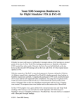
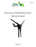
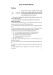
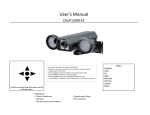
Avro Lancastrian
A Plane Design Production
PLANE-DESIGN AVRO LANCASTRIAN USER MANUAL V2.0
CONTENTS
INTRODUCTION
3
COPYRIGHT NOTICE
3
CREDITS
3
LANCASTRIAN HISTORY
4
LANCASTRIAN SPECIFICATION
5
OPERATIONAL PROCEDURES
7
LOCATION OF CONTROLS
10
FUEL SYSTEM
13
CONTROLS & INSTRUMENTS DESCRIBED
13
THINGS YOU MIGHT NOT HAVE NOTICED
14
COPYRIGHT © 2005 PLANE-DESIGN.COM
2
PLANE-DESIGN AVRO LANCASTRIAN USER MANUAL V2.0
INTRODUCTION
We present the first product from Plane Design - the Avro Lancastrian. This model includes a Virtual
Cockpit with fully working controls and instruments with the added reality of animated precipitation effects.
Due to the positioning of the radio in the real life cockpit, it has been added as a popup display.
The external model is highly detailed with reflective skins and is fully animated.
Authentic Rolls Royce Merlin engine sounds are included, allowing you to experience the mighty
Lancastrian to the fullest.
All major components were created using copies of the original Avro drawings, allowing us to produce a
truly accurate model.
C O PYR I G H T
This model and all accompanying files, excluding the sextant, are a commercial product and should NOT be
treated as freeware.
The files may not be copied (other than for backup purposes), transmitted, passed to third parties or altered in
any way without the prior permission of Plane Design. Any breach of the aforementioned copyright will
result in the full force of law being brought to bear on those responsible.
The bubble sextant is copyright Mark Beaumont and Dave Bitzer, and is included with their permission.
Copyright © 2005 Plane Design
www.plane-design.com
CREDITS
Visual Models
Aircraft Textures
Gauge Programming
Sounds
Flight Dynamics
Testing
Manual
Ed Walters
Ken Scott & Ed Walters
Ed Walters
Ed Walters
Ken Scott
Ken Scott, Bill Leaming
Ed Walters
The bubble sextant is included by kind permission of Mark Beaumont and Dave Bitzer. For details on how to
use the sextant, please consult the Sextant manual.
COPYRIGHT © 2005 PLANE-DESIGN.COM
3
PLANE-DESIGN AVRO LANCASTRIAN USER MANUAL V2.0
A V R O T Y P E 691 L A N C A S T R I A N H I S T O R Y
The Avro Lancastrian was developed from the famous Lancaster bomber. Canadian produced Lancasters
were built at Victory Aircraft in Toronto. The factory converted British built Lancaster R5727 into a
passenger carrying aircraft for the Trans-Canada Air Lines. In its new guise, as the Lancaster XPP, the
aircraft was flown to Britain where it was further modified by Avro. The conversion was developed further
into the Lancaster Mailplane, which was later renamed the Lancastrian. In late 1943 Lancaster DV379
was the first aircraft so converted.
The first aircraft built as Lancastrians (designated the Lancastrian Mk 1) were sold to British Overseas
Airways Corporation (BOAC) for use on a service to Australia. These aircraft had accommodation for nine
passengers on seats facing starboard which could be converted into six bunks. Luggage was carried in the
nose and tail. The service was flown between Hurn, Hampshire, England and Sydney, Australia. Flights
commenced on May 31st 1945, with the war still raging in the Pacific. BOAC bought 21 Lancastrian Mk Is,
and operated them until 1950, latterly on freight and mail services.
The Lancastrian C. Mk 2 was essentially similar to the Mk 1 and was produced for RAF Transport
Command. These aircraft were used for long range flights to India, the Far East and Australia, often as VIP
transport.
The Mk 3 Lancastrian was developed specifically for British South American Airways (BSAA). The first
flight out of Heathrow airport was on January 1st 1946, when BSAA Lancastrian G-AGWG "Star Bright"
set off on a proving flight to Buenos Aires, with Captain D.C.T. Bennett at the controls. By June, a regular
service to Santiago had been established. Lancastrian 3s were also supplied to Skyways, Flight Refuelling,
Silver City and Alitalia. The passenger accommodation in these aircraft was side by side standard airline
seats.
Ten Lancastrian C. Mk.4s were supplied to RAF Transport Command, but soon were passed to civil
airlines to fill the shortfall from the failure of the Avro Tudor.
The Lancastrian 3, G-AGWH “Star Dust”, as depicted in this package, was lost in mysterious
circumstances in the Andes on a flight to Santiago - the aircraft transmitted a Morse code message at 17:41,
announcing an ETA of 17:45, followed by the mysterious word “STENDEC”, which was repeated twice.
Nothing more was heard from the aircraft, until in January 2000, a Merlin engine emerged from a glacier in
the Andes. The aircraft had apparently flown into the summit of Mt. Tupangato, and the wreckage had been
hidden in the snow.
Lancastrians operated by Flight Refuelling Ltd and Skyways also saw service in the Berlin Air Lift,
between June 1948 and August 1949, from Tarrant Rushton in Dorset. Each aircraft carried between 1500
and 2300 gallons of petrol to the beleaguered city. In total, Flight Refuelling’s Lancastrians and Lancasters
transported 7 million gallons, making a huge contribution to the effort.
COPYRIGHT © 2005 PLANE-DESIGN.COM
4
PLANE-DESIGN AVRO LANCASTRIAN USER MANUAL V2.0
A V R O T Y P E 691 L A N C A S T R I A N S P E C I F I C A T I O N
DIMENSIONS:
Span: 102 ft
Length: 76 ft 10 in
Height: 19 ft 6 in
Wing Area: 1297 sq ft
POWER PLANT:
Four 1280 hp Rolls Royce Merlin T24/2 /Merlin 500/2 twelve cylinder vee liquid cooled engines.
Fuel capacity 2,154 Imperial Gallons in wings, 1,020 Imperial Gallons in fuselage.
WEIGHTS:
Tare Weight: 30,426 lb
Weight Loaded: 65,000 lb
Wing Loading: 50.10 lb/sq ft
Power Loading: 12.7 lb/hp
PERFORMANCE:
Maximum speed (at 53,000lb): 295 mph at 3500 ft and 310 mph at 12,000 ft.
Maximum cruising speed (weak mixture): 275 mph at 11,000ft and 285 mph at 17,500 ft
Rate of climb (at 65,000lb): 750ft/min at 9500 ft and 550 ft/min at 16,000 ft.
Service ceiling: 23,000 ft
RANGES (under still conditions at 15,000 ft with no allowance for climb):
At maximum weak mixture cruising speed (265 mph): 3570 miles
At most economical cruising speed (200 mph): 4,501 miles
ACCOMMODATION:
Crew of two pilots, one navigator, one wireless operator, one steward, with thirteen passengers.
COPYRIGHT © 2005 PLANE-DESIGN.COM
5
PLANE-DESIGN AVRO LANCASTRIAN USER MANUAL V2.0
COPYRIGHT © 2005 PLANE-DESIGN.COM
6
PLANE-DESIGN AVRO LANCASTRIAN USER MANUAL V2.0
O PE RAT I O NAL PR O C E D U R E S
Before Starting
[ ] Master Engine Cocks
[ ] Throttles
[ ] Propeller Controls
[ ] Radiator Shutters
[ ] Fuel tank selectors
OFF
Cracked open
Fully up
Over-ride switches at AUTOMATIC
No. 2 Tanks
Starting
Press CTRL+E to initiate engine autostart sequence, or:
FOR EACH ENGINE:
[ ] Master Engine Cock
ON
[ ] Magnetos
BOTH ON
[ ] Starter Push Button
Taxi-Warm-up
[ ] Radiator shutters
[ ] Brakes
[ ] Gyro Instruments
[ ] Altimeter
[ ] Flight Instruments
[ ] Carb Heat
[ ] Navigation Lights
OVER-RIDE
CHECK
CHECK
CHECK
CHECK
CHECK
As required
Engine run-up
[ ] Parking Brake
SET
[ ] Temperatures & Pressures CHECK
[ ] Throttle
1500 RPM
[ ] Suction
CHECK
[ ] Magneto
CHECK <100 rpm drop on each; <40 rpm drop between
[ ] Throttle
4 PSI
[ ] Propeller Controls
Check RPM falls to 1800 RPM when levers full down
[ ] Throttle
24 PSI
[ ] Propeller Controls
Full up
[ ] Boost & RPM
Check takeoff settings
[ ] Throttle
9 PSI
COPYRIGHT © 2005 PLANE-DESIGN.COM
7
PLANE-DESIGN AVRO LANCASTRIAN USER MANUAL V2.0
Pre Take Off
[ ] Auto Controls Clutch
[ ] Pitot Heat
[ ] Trim
[ ] Flight Controls
[ ] Flaps
[ ] Carb Heat
[ ] Heading Indicator
Take Off
[ ] Brakes
[ ] Throttles
[ ] Airspeed
OUT
ON
Elevator slightly forward
Rudder neutral
Elevator neutral
FREE AND CORRECT
15° to 20°
COLD
CHECK
[ ] Landing Gear
[ ] Flaps
RELEASE
FULL
Ease aircraft off the ground at not less than 95 MPH at 50,000lb or 105 MPH at
60,000lb
UP
(when positive rate of climb is established)
RETRACT
Climb
[ ] Airspeed
160 MPH for a quick climb. Most comfortable climbing speed 175 MPH
After Take off and Climb
[ ] Landing Gear
[ ] Flaps
[ ] Temperature/Pressures
[ ] Landing Lights
[ ] Throttles
VERIFY UP
VERIFY UP
CHECK
AS REQUIRED
VERIFY FULL
Cruise (Ideally at 15,000 feet MSL)
[ ] Boost
7 PSI
[ ] Airspeed
170 MPH
[ ] RPM
1800 RPM minimum
Descent
[ ] Altimeters
[ ] Fuel Quantity
[ ] Landing Lights
SET
CHECK
AS REQUIRED
COPYRIGHT © 2005 PLANE-DESIGN.COM
8
PLANE-DESIGN AVRO LANCASTRIAN USER MANUAL V2.0
Approach
[ ] Auto Controls Cock
[ ] Flaps
[ ] Undercarriage
[ ] Propellers
[ ] Flaps
[ ] Airspeed
OUT
20° on circuit
DOWN
At least 2,850RPM
DOWN on final approach
110MPH-130MPH IAS
After Landing
[ ] Flaps
[ ] Radiator shutters
[ ] Landing Lights
UP
OVER-RIDE
AS REQUIRED
Engine Shut Down
[ ] Parking Brakes
[ ] Navigation Lights
[ ] Master Engine Cocks
[ ] Magnetos
SET
OFF
OFF
OFF
NOTE: This aircraft's real-world checklists have been modified for use with Flight Simulator.
COPYRIGHT © 2005 PLANE-DESIGN.COM
9
PLANE-DESIGN AVRO LANCASTRIAN USER MANUAL V2.0
LO CAT I O N O F C O NT R O LS
1.
2.
3.
4.
5.
6.
7.
8.
9.
10.
11.
12.
13.
14.
15.
DF Indicator
Undercarriage Indicator switch
D.R. Compass Repeater
Flaps indicator switch
Ignition Switches
Flaps indicator
Booster coil switch
Engine starter push buttons (4)
Boost gauges (4)
Suction gauge
Vacuum change-over cock
Oxygen regulator
Supercharger control switches (linked together)
Air supply and brakes pressure gauge
Feathering push buttons (4)
COPYRIGHT © 2005 PLANE-DESIGN.COM
16.
17.
18.
19.
20.
21.
22.
23.
24.
25.
26.
27.
28.
29.
30.
Fire warning lights (4)
Signalling switchbox (non functioning)
Fire extinguisher pushbuttons (4) (non functioning)
Superchargers warning light
Starboard master fuel cocks (2)
Throttle control levers (4)
Propeller control levers (4)
Port master fuel cocks (2)
Signalling Switchbox
DR Compass switches
Identification lights switches
Compass
Undercarriage position indicator
Beam Approach Indicator
Clock
10
PLANE-DESIGN AVRO LANCASTRIAN USER MANUAL V2.0
31.
32.
33.
34.
35.
36.
37.
38.
Navigation lights switch
Seat raising lever
Mixer Box
Beam approach control unit
Oxygen connection
Auto controls attitude control
Auto controls cock
Auto controls clutch
COPYRIGHT © 2005 PLANE-DESIGN.COM
39.
40.
41.
42.
43.
44.
45.
46.
Brake lever
Windscreen de-icer pump
Flaps selector
Aileron trimming control
Elevator trimming control
Rudder trimming control
Undercarriage control lever
Undercarriage control safety bolts
11
PLANE-DESIGN AVRO LANCASTRIAN USER MANUAL V2.0
47.
48.
49.
50.
51.
52.
53.
Ammeter
Oil pressure gauges
Pressure-head heater switch
Oil temperature gauges
Coolant temperature gauges
Fuel contents gauges
Inspection lamp socket
54.
55.
56.
57.
58.
59.
Fuel contents gauge switch
Fuel tank selector cocks
Fuel transfer switches
Fuel pressure warning lights
Emergency air control
Oil dilution buttons (non functioning)
C O N T R O L S N O T S H O W N:
Cross feed cock
Carburettor Heat
Radiator shutter switches
COPYRIGHT © 2005 PLANE-DESIGN.COM
Front spar cover, under step
On floor at left of pilot’s seat
On starboard cockpit wall
12
PLANE-DESIGN AVRO LANCASTRIAN USER MANUAL V2.0
F U E L SYS T E M E X PLAI N E D
The fuel system in the real Lancastrian had 3 tanks in each wing and one central fuselage tank, located in the
position of the bomb bay in the Lancaster.
The engines drew fuel from the no.1 and no.2 wing tanks; fuel could only be transferred from the no.3 tank
and fuselage tanks into the no. 2 and no. 1 tanks respectively.
Due to the limitations in FS2004’s fuel systems modelling, we have been forced to compromise. The main
fuel selector taps allow the selection of the no. 1 and no. 2 tanks (as per the real aircraft), however, when the
fuel transfer switches are selected, the engines feed from the fuselage or no. 3 tanks, as outlined by the table
below.
Fuel tap position
Fuel transfer switch
Tank in use
1
Off
1
1
On
Fuselage
2
Off
2
2
On
3
When either the Fuselage or no.3 tanks are exhausted, the system will automatically switch back to the no.1
or no.2 tanks respectively.
CONTROLS & INSTRUMENTS DESCRIBED
As the Lancastrian instrumentation is unlike most modern instrumentation, a short description of some of the
instruments and controls follows.
1. Autopilot system. In keeping with the aircraft’s age, the autopilot is very basic. It will hold the heading
and attitude, and is engaged with the “AUTOPILOT CLUTCH”. The attitude setting can be altered using
the “AUTO CONTROLS ATTITUDE CONTROL”.
2. The “STANDARD BEAM APPROACH” system was similar to the ILS system in modern aircraft, and
we have modelled it to use the ILS signals in FS2004. The light on the left marked “O” is the Outer Beacon
marker, and the one marked “I” is the Inner Beacon marker. The vertical needle at the bottom shows the
lateral offset from the runway centreline and the horizontal needle shows the vertical offset from the
glideslope. These needles operate in the same sense as in a conventional ILS gauge, i.e. the needle shows the
direction to fly to get onto the glideslope and runway centreline.
3. The “DF INDICATOR”. This gauge will allow you to home on an ADF beacon. To home on a beacon,
tune the main radio (Shift+5) to the frequency of the beacon. Unless you are pointing directly at the beacon,
COPYRIGHT © 2005 PLANE-DESIGN.COM
13
PLANE-DESIGN AVRO LANCASTRIAN USER MANUAL V2.0
the needles will flick over to one side, with one needle almost horizontal, and the other needle vertical. Turn
towards the vertical needle, i.e. if the right needle is vertical, turn to starboard. Eventually the needles should
settle down so they are crossed over the yellow centre line.
4. The “BRAKE TRIPLE PRESSURE GAUGE” shows the air pressure to each wheel brake, and the large
needle shows the system air pressure.
T H I N G S YO U M I G HT N OT HAVE N OT I C E D . . .
1. When the engines are shut down and the parking brake is applied, chocks and a starter trolley will appear.
2.. If you click the side window frames, the sliding windows will open and close.
3. If you click the co-pilot’s seat and seat back, they will fold.
4. Click the armrests to move them.
CLOSING REMARKS
We hope that you enjoy our first release. If you have any comments or suggestions, please contact us at
[email protected]
We are currently developing an Avro Lancaster to complement this package, and we expect this to be
released in Q1 2005, and have many exciting projects planned to follow.
Ed Walters & Ken Scott - Plane Design
www.plane-design.com
COPYRIGHT © 2005 PLANE-DESIGN.COM
14