1
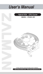
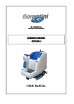
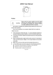
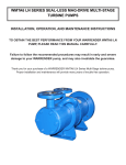
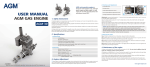
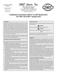
AT21-70 User Manual Preface Please read this manual carefully, also with related CAUTION: manual for the machinery before use the controller. For installing and operating the controller properly and safely, qualified personnel are required. This product is designed for specified sewing machines and must not be used for other purposes. If you have any problem or any comment, please feel free to contact us. Safety Instruction 1. All the instruction marked with sign must be absolutely observed or executed; otherwise, personal injuries or risk to the machine might occur. 2. This product should be installed and operated by persons with appropriate training only. 3. Before connecting power supply cords to power sources, it’s necessary to make sure that the power voltage is in the range indicated on the product name plate. 4. Make sure to move your feet away from the pedals while power on. 5. 6. Turn off the power and remove plug prior to the following operations: Connecting or disconnecting any connectors on the control box. Repairing or doing any mechanical adjustment. Threading needle or raising the machine arm. Machine is out of work. Make sure to fasten all the fasteners firmly in the control boxes prior to the operation of the system. 7. Allow an interval of at least 30 seconds before repowering the system after power off. 8. Repairs and maintenance work may be carried out by special trained electronic technicians. 9. All the replacement parts for repairing must be provided or approved by the manufacturer. 1/8 - 10. The controller must be firmly connected to a properly grounded outlet. Be sure to connect the controller to a properly grounded outlet. If the grounding connection is not secured, you CAUTION: may run a high risk of receiving a serious electric shock, and the controller may operate abnormally. 1 Product Introduction 1.1 Overview AT21-70 Series Digital AC Servo System, the motor and the controller are separately mounted on the same bracket, providing a very flexible mounting solution for customers. The system can execute needle-down (or needle-up) position with external-synchronizer. And it can be easily configured with different motors to match with various sewing machines, such as lockstitch, dual-needle lockstitch, heavy duty, over-lock stitch, interlock stitch and direct-driven sewing machines. Employing a switch-mode power supply for the sensitive control circuitry, the system can operate over a much wider voltage range. Installed easy, Great Torque, small cubage, low-noise, high-efficiency, small shake and high-precision speed control. Specially equipped with 700W high power, high torque motor, it has greatly enhanced and the load capacity of the system. Side-mount connectors make the connection more reliable and reduce the malfunction caused by oil leakage. Applicable to thick material of machine, roller cars and special machines that require larger torque. 1.2 The outside view of AT21-70 The front and side of the controller are shown in Fig. 1-1 and 1-2: Fig.1-1 Fig. 1-2 2/8 - 1.3 Specification 2 Controller Type AT21-70 Motor Type AC Sever Motor Voltage Range AC 220 V ±20% Frequency Range 50Hz,60Hz Input current 7.0A Max. Sewing Speed 2500rpm Max. Torque 7.5Nm Weight(including motor) 7.0Kg Dimension 375X325X280mm Installation Instructions 2.1 Installation steps for down hang motor Step 1: Install the lifting bolts, if the board of the sewing machine has no positioning holes, drill the hole as shown in Fig.2, and Install the lifting bolt into the hole. Fig. 2 Step 2: install the motor (see Figure 3 and Figure 4). Hang the motor on the lifting bolts and then fix the motor. Fig.3 lifting bolts(A、B、C) Fig. 4 motor installation figure 3/8 - 3 Operation Instruction In the speed control, there is no wheel-belt ratio parameter setting, so The speed of controller DIP switch setting is speed of the motor shaft. 3.1 Connections of the controller cables 1. The motor power line is connected through a 5PIN interface, and the connection is shown in fig.10. 2. The connection of the motor encoder cables is shown in fig.11: Motor encoder cable has a plug or two, the left side is the motor HALL line and the right side is the encoder cable plug. 3. The connection of the operation pedal cable is shown in figure 12. Fig.10 Fig.11 Fig.12 3.2 The Switch Setting There are two modular switches. One is four bits, the other is five bits in the hardware circuit board. The switch of four bits is for the speed settings of the motor. The switch of five bits is for the machine model, turn direction of the motor, whether or not external synchronous encoder and automatic test set. The explicit operations are as follows: 3.2.1 The Five bits Switch Setting The five bits switch setting is shown in fig.13: fig.13 1. bit 1and bit 2 to set model: The parameter has been set out the factory, the installation can not toggle, it can push any location. 2. bit3 to set motor turn direction a) bit3 represents OFF, set the motor circumrotate in counter-clockwise 4/8 - b) bit3 represents ON, set the motor circumrotate in clockwise. 3. bit4 is used for setting synchronizer. it’s very important part to executes needle up/down position function. a) b) bit4 represents OFF, The system can run without synchronizer. and the machine can’t execute needle up/down position function. bit4 represents ON, The system can’t be run without synchronizer. and The machine can execute needle up/down position function 4. Bit5 to set automatic test a) bit5 represents OFF, set automatic test function close and the machine can be controlled running by operation pedal. b) bit5 represents ON, set automatic test function open. Motor will automatically run a certain number of needles, After a while, and then The motor will automatically run again. The cycle repeated until disable this setting or off power. (Normally, the default running time is 5seconds and stop time is 5 seconds) 3.2.2 The 4 bits Switch Setting The 4bits switch setting the motor output shaft with the highest speed, fig.14: fig.14 Setting rule as follows: bit4 represents the highest bit,bit1 represents the lowest bit. Each part represents ON is shown 1, represents OFF is shown 0.This four parts represent 4 bits binary digit, from (0000-1111), can set 16 kind speed, from the lowest speed 250RPM to the highest speed 2500RPM,each grade represents 150RPM difference, the detail operations please see as follows: 1. 250RPM,as shown: (bit4→0000←bit1); 2. 400RPM,as shown: (bit4→0001←bit1); 3. 550RPM,as shown: (bit4→0010←bit1); 4.700RPM,as shown: (bit4→0011←bit1); 5/8 - 5. 850RPM,as shown: (bit4→0100←bit1); 6. 1000RPM,as shown: (bit4→0101←bit1); 7. 1150RPM,as shown: (bit4→0110←bit1); 8 .1300RPM,as shown: (bit4→0111←bit1); 9. 1450RPM,as shown: (bit4→1000←bit1); 10. 1600RPM,as shown: (bit4→1001←bit1); 11. 1750RPM,as shown: (bit4→1010←bit1); 12. 1900RPM,as shown: (bit4→1011←bit1); 13. 2050RPM,as shown: (bit4→1100←bit1); 14. 2200RPM,as shown: (bit4→1101←bit1); 15. 2350RPM,as shown: (bit4→1110←bit1); 16. 2500RPM,as shown: (bit4→1111←bit1); 3.3 Needle Stop (up/down) Position The system can execute needle stop(up/down) position by the synchronizer with coder , 1. The installation of synchronizer (external), shown as follow: Connects the cable of the synchronizer to the jack of PCB. Sets the part 4 of the five parts switch to ON position(3.2.1 The Five parts Switch Setting), to set needle stop position(needle up/down position). Fig.15 2. Wheel-belt ratio test (The function is only applicable in synchronized encoders’ conditions): this machine can auto–test wheel-belt ratio. In order to having no HMI, so 6/8 - if finding the machine runs more 1 circle at first times, please don’t take care it. because it is correct (normal phenomenon). 3. Stop needle up and down setting: stop needle up and down is shown as follow: Power-on the system, turns hand wheel clockwise, when the LED of synchronizer is from light to dark, this position is needle up position. When the LED of synchronizer is from dark to light, this position is needle down position. (if the needle up/down position is not match with mechanical location, please loose the screw, then adjust films and correct the needle position. then fasten the screw.) fig.16 fig.17 4. backward Pedal needle up position: At the motor circulate, if pressing backward the pedal, the machine will stop at the needle up position if the machine was already stop at the needle up position, the motor makes motionless, otherwise the motor will run and stop at the needle up position. 5. Needle up/down position setting: There is a switch in front of the controller box (see fig.18).The machine will be set at needle up position during setting the switch to up location. The machine will be set at needle down position during setting the switch to down location. fig.18 3.4 Error Codes Instructions It has automatic fault detection function. The demonstration of the fault is shown through the blinking of the red light. If it blinks only the red light, the number of the continuous blinking of red light in short intervals represents the code of the fault; if the green light and the red light blink alternatively, it means that the number of the fault is larger than 10, and the number of the fault is the continuous blinking times of the red light plus 10. 4 error code Recovery processing and maintenance meaning solution 7/8 - 01 03 05 07 08 11 13 15 16 17 18 19 Turn off the system power, restart it after 30 seconds, if the controller still does not work, please replace it and inform the manufacturer. Shut down the controller, check input power voltage, if the voltage is lower than 148V. please restart the controller after the voltage is resumed. If the system low voltage controller still does not work when the voltage is at normal level, please replace the controller and inform the manufacturer. Shut down the controller, Check input power voltage, if the voltage is higher over-voltage in than 275V. please restart the controller after the normal voltage is resumed. If operation the controller still does not work when the voltage is at normal level, please replace the controller and inform the manufacturer. electrical current Turn off the system power, restart it after 30 seconds, if it still can not work. If detected circuit such failure happens frequently, ask and inform manufacture technical failure support. Disconnect the controller power, check if the motor input plug is off, loose or damaged, or if there is something wrapped on the machine head. After Motor Stalled checking and correction, if the system still does not work, please replace the controller and inform the manufacturer. Shut down the power. the detection of external encoder connector is loose or fell off. Restore it, then restart the system; if it still does not work, please Synchronizer failure replace the synchronizer. if it still does not work, please notify the factory and replace the controller. Turn off the system power, check if the motor sensor plug is loose or dropped Motor HALL failure off, restore it and restart the system. If it still does not work, please replace the controller and inform the manufacturer. Turn off the system power, turn on again in 30 seconds to see if it works. If Motor over-speed not, try several more times, if such failure happens frequently, please change protection the controller and inform the manufacturer. Turn off the system power, restart the system after 30 seconds, if it still does Motor reversion not work, please replace the controller and inform the manufacturer. Turn off the system power, restart the system after 30 seconds, if it still does ESD failure not work, please replace the controller and inform the manufacturer. Turn off the system power, restart the system after 30 seconds, if it still does Motor overload not work, please replace the controller and inform the manufacturer. Shut down the power,check and make sure the connector is correct. If the Speed encoder of controller still does not work after Restart the system, Please replace it and alarm inform manufacturer hardware overflow End 386P00366 2009-10 版本 A 8/8 -