1
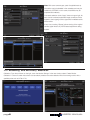
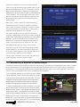
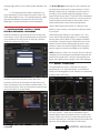
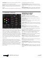
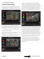
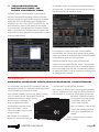
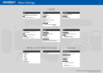
image processing system
IS-100
USERS
MANUAL
image processing
system IS-100
Table of contents
A OVERVIEW1
B START UP
1
B1 Initial Settings
1
B2 Calibrating the Primary Monitor
2
B3 Creating a Camera Calibration
3
C WORKING WITH THE
PREVIEWED IMAGE
4
C1 CDL method
5
Definitions of CDL control panel items
5
C2 Tone Curve method 6
Definitions of tone curve control panel items
6
C3 6 Color method
7
Definitions of 6 color control panel items:
7
c4 Analysis Tools
8
Image Analysis Functions
8
D TRANSFERRING INFORMATION TO
POST PRODUCTION
9
APPENDIX: MISCELLANEOUS AND
MAINTENANCE FUNCTIONS
page2
9
USERS MANUAL
A OVERVIEW
B START UP
Basic hardware connection and setup instructions are
detailed in the manual “Fujifilm CCBOXX IS-100 Instructions.”
Power-on the CCBOXX and wifi router. Start up sequence
and self-check take about 30 seconds.
The video processing and signal routing are performed fully
inside the CCBOXX hardware unit itself, but the end user
controls the functions and creates the looks via either an
Apple iPad™* or Apple computer (notebook or desktop
type). The software is available via free download from the
Apple iTunes™* App Store.
Confirm that the front panel of the CCBOXX shows an IP
address. Normally, it will show an address for the “CCBOXX”
and the “Controller” line will say “Not Connected.”
The user interface was designed to be simple and intuitive
with a quick learning curve. Whereas the following guide
is designed for iPad™ users, computer users simply use
standard mouse-click operation instead of “touch and drag”.
The basic CCBOXX sequence of operations during use:
A. The incoming camera signal is transformed into the
ACES color space (primary setup options) by way of an
“Input Device Transform” (IDT). The user also selects the
intended viewing environment for the final output, the
“Reference Rendering Transform” (RRT).
B. The primary monitor allows this signal to be precisely
viewed due to the on board color profiling function
(performed on regular basis as determined by individual
needs).
C. “Scenes” are created. Up to 200 scenes may be stored
per day. The total number of scenes is limited only by
storage space on the device.
D. “Looks” are created within each scene. Up to 99 looks
may be stored for each. The desired image result is
previewed in real time on the primary monitor. Other onset users can also view the video output via a secondary
SDI connection.
E. The instructions concerning the “looks” and still reference
images to be used in the final color suite are simply
exported onto a USB flash memory device and delivered
along with the camera capture data or ingested into any
compatible “dailes” creation system.
On the iPad™, verify wifi network settings in the iPad™’s
settings menu as needed and join the proper wireless network
of the router connected to CCBOXX. Normally, DHCP will
work, but if necessary, set static IP address on the iPad to
correspond accordingly to the address of the hardware unit.
Launch the CCBOXX App on the iPad™. On the log-in window,
you will see both the iPad’s™ address and the CCBOXX’s
address. If not, type in the CCBOXX IP and touch the “+” button
to begin connection. If connection fails, it may be necessary to
check the network settings again on the iPad™.
B1 Initial Settings:
Once connection between controller and hardware is
established, the app will automatically proceed to the initial
set-up screen (“Main”).
Note: The CCBOXX does not record any video or audio
image data. All adjustments/corrections are virtual. Neither
the camera itself nor the monitor is affected in any way by
any CCBOXX operations.
_______________
*iPad™ and iTunes™ are registered trademarks of Apple, Inc.
USERS MANUAL
From the first drop down menu at upper left:
• Choose camera type and shooting settings.
• Select correct signal type.
• Choose intended rendering type for accurate previewing.
• Choose correct general settings for primary on-set
monitor.
page1
Note: With some camera types, parts of applicable set-up
information may be imbedded in the metadata, and may be
readable by CCBOXX. In such cases, those fields may be
populated automatically.
Enter each selection via the “Apply” button at upper right. As
each choice is entered, applicable image corrections will be
applied to the outgoing monitor signal and immediate results
will be visible.
At any time, touching “Bypass” allows viewing of the original
camera signal without any ACES-based adjustments being
applied.
B2 Profiling the Primary Monitor
Calibration: From the pull-down on the right, touch the Monitor Settings. In the new window, select “Create Monitor
Calibration”. Follow on-screen instructions to automatically create an accurate calibration file of the viewing monitor with a
qualified probe such as X-Rite i1 Pro.
page2
USERS MANUAL
Options are presented for the amount of data patches
used. Using more does yield a higher quality profile, but can
take a considerable amount of time. For example, the “165
patch” takes approximately 5 minutes to complete and is
satisfactory for most purposes. An option is also available for
“Data Evaluation”. This is a secondary routine which runs a
series of color patches with the calibration applied in order
to verify the monitor’s precision and present the results in
graphic fashion.
When using 2 primary monitors in a dual camera set-up,
the calibration profile must first be created by attaching
each monitor to Output A, individually. The second monitor
can then be attached to Output B and its corresponding
calibration can be applied from the controller.
The monitor should be of a high quality for professional
purposes. Carefully adjust the monitor’s on-board settings to
minimize any signal processing that affects color and gamma
(contrast). The monitor should be set to its “Native” color
space if such is provided. For example, choose “None” if
there is such an option for Color Space, not “Rec. 709”.
With single camera type of shooting, only the monitor
attached to Output A will be fully accurate because of the
applied calibration. The monitor attached to Output B will
be in a Rec. 709/D65/gamma 2.35 format and reflecting the
current look being applied from the controller.
If shooting with 2 cameras, Output A and Output B can be
used to separately view each camera’s image.
B3 Creating a Camera Calibration
Choosing the camera type in the first step above sets the proper IDT and creates an immediately improved preview. However,
to fine tune the preview for location lighting variances and other influences such as color tint of lens glass, it is helpful to do
a calibration. It is recommended that this process be performed with a grey card, or color chart being held in front of the
camera, and the camera adjusted for what is considered a normal exposure.
From the Calibration Pull-down, touch “Camera” and then “Create
Camera Calibration”. On the next screen there will be short pause
as the app fetches a frame grab from the video stream. The RGB
histograms at left can be used to analyze the color values of any
individual point on the capture frame and assist in verifying the
suitability of the intended neutral target and its exposure level.
To select the desired target aim point for calibration, touch and
drag on the grey card in the frame, or upon whichever area is
desired to be the “neutral”. A red-bounded rectangular area will
appear on the screen. The CCBOXX will detect the luminance
range of the area selected. Alternatively, you can select the desired
percentage of luminosity corresponding to the exposure and
neutral area. (Note: a color offset can be intentionally created by
touching on the numeric values next to R, G, or B and manually
USERS MANUAL
page3
choosing target values). Touch “Create Camera Calibration” and
Apply.
a. OCV (Original Camera Value) is scaled from 0 to
1023, representing 10 bits of range from black to white. The
ACES scale ranges from 0 to 1.0. In standard practice, middle
grey should be between 380 and 445 on the OCV scale,
depending on camera manufacturer’s recommendations.
C WORKING WITH THE
PREVIEWED IMAGE
CCBOXX provides an organizational structure to keep track
of the various “Looks” that are created during the production.
It is a possible to have 200 Scenes for each day, and each
Scene can contain up to 99 Looks.
The Scene Manager screen lists all Looks created for any
one particular scene and a live preview window. In Scene
Manager, saved looks can be applied to the live action by
touching on its thumbnail image and dragging it into the
larger Preview window above. The active Look is indicated by
a red boundary box. Simply touching on a Look’s thumbnail
image will display that still image on the preview monitor,
without affecting the currently active look application.
Create a New Scene button brings up a dialog box that
allows for custom naming, comments and other information
to be entered.
Three methods are offered for Look creation: CDL, Tone
Curve, and Six-Way. Applied together in a concatenated
manner, these controls allow for a high degree of flexibility
and precision. Operations may be performed in any of the
method windows without affecting settings done in other
windows. In each look method, Bypass allows the user to
view the signal from camera unmodified by the CCBOXX.
NOTE: Whenever a “New Look” is saved, the time code and
metadata from the camera are automatically referenced and
saved with the stored look. That look is also applied to the
signal, until a different look is applied in the Scene Manager.
C1 CDL method:
This panel allows the user to modify the look using the
standard tools of Lift, Gamma and Gain, or the American
Society of Cinematographer’s Color Decision List parameters
of Offset, Slope, and Power.
The Main screen lists all Scenes for every day of the
production (which can be accessed via a daily history pull
down), and allows the user to delete unwanted scenes. This
is also the place from which the Look files are exported every
day for submission to the post facility.
Lift, Gain, Gamma – These controls are different ways to
express adjustments to the transfer function in similar ways
to Slope, Offset, and Power. Lift controls the black level and
low end of the spectrum, while Gain adjusts the shoulder and
high end. Gamma adjusts the linearity of the function.
page4
USERS MANUAL
The Power function essentially changes the shape of the
curve and will taper the curve around middle grey. Adjusting
in the negative direction (to the left) will result in an exponent
less than one, and will cause the low end (near 0.0) of the
function, and the high end, (near 1.0) to become darker, or
move lower on the graph. Adjusting in the positive direction
will simultaneously raise the low end and the high end of the
function to become brighter.
It is important to note that while traditionally, these values can
be adjusted independently of one another, in the CCBOXX
System, they currently are linked to preserve middle grey.
The basic transfer function without modification appears as
a straight diagonal line starting at 0.0 (on the bottom left) and
extending up to 1.0 (on the upper right). The input value is
represented by the x-axis, while the Y-axis represents the output
value. Given this logic, by moving the line below the basic
unmodified function, you are making the image darker, and by
raising the function above the original you make the image lighter.
Offset: Adjusts the vertical offset of transfer function. Positive
adjustments decrease “density,” and negative adjustments
increase “density.”
Slope: Adjusts the angle of the transfer function. Positive
adjustments yield a steeper angle, negative adjustments yield
a shallower angle.
Power: Adjusts the shape or curve of the transfer function.
Positive adjustments cause the function to slope more
gently starting from 0 and rise more quickly approaching 1.0,
negative adjustments cause the function to slope more quickly
starting from 0 and for the slope to taper off approaching 1.0
Adjusting offset shifts the vertical positioning of the entire transfer
function. Adjustment in the negative direction (sliding the jog
wheel to the left) will lower the values evenly across the entire set
for the image, making the image darker. Conversely, adjusting
the offset to the right will raise the entire function vertically on the
graph, and will cause the image to be lighter.
The Slope function adjusts the angle of the transfer function,
so a negative adjustment will cause the angle to be shallower,
meaning the lower values (below middle gray or ~0.4 or 0.5)
will be made to output brighter, while the brighter values in
the image or highlights (above middle grey or x>~0.5) will be
made to output darker values.
USERS MANUAL
The above descriptions apply to adjusting the grey channel,
or the overall luminosity information in the image. However, all
of these transformations can also be applied to the individual
color channels, using either the color wheels above the jog
wheels, or by selecting a color channel using the channel
selector underneath the RGB Transfer Function. Selecting
a channel using this control will cause the text in the edit
window and the text next to the jog wheels to represent the
current channel being actively controlled.
When using the color wheels on any of the controls, the
overall luminosity will not be affected (represented in the
display area by the gray transfer function on the right), but
the tonality will be changed, and will be reflected in the RGB
transfer function overlay on the right of the display area.
Definitions of CDL
control panel items:
Scene Manager: navigates back to scene management
Title Bar: Indicates the user is modifying the CDL panel of
the box with the IP address listed
Lock: Prevents changes to Look from being saved.
Save as new Look: Saves the current look as a new look to
the scene manager.
Timecode: Displays the current timecode
Date: Displays the date of the scene being worked on
Scene Name: Displays the Scene name
Reset All: Resets all three color correction panels to either
Default look or the Scene look.
CDL Reset: Resets all values on the CDL Panel
Undo: Canels last user command on CDL panel and steps
back in history.
Redo: Re-applies last user input on CDL panel.
Look Toggle: Allows user to quickly turn off look preview
on monitor, to toggle between corrected look, and the basic
look from ACES with no modification
Import CDL: Function currently not available.
page5
Capture: Captures a framegrab from the current live picture
and creates a new look with all applied settings as of that
frame. Look is not applied, but available for editing.
Pause/Play: Holds the current frame for grading, or returns
to the feed if a frame is currently being held
Bypass: Disables all CCBOXX image processing and ACES
transforms, displays the Original Code Value output of the
camera.
Live: switches the monitor between the live video signal and
the framegrab associated with the look
Rendering Warning: Highlights in bright pink that which is
outside the gamut of target display you selected at rendering
setting.
Monitoring Warning: Highlights in bright green image areas
that fall outside of the reproduction capabilities of the primary
monitor.
RGB Tone Curve: Displays an overlay of the current tone
curves for the Red Green and Blue Channels as they are
defined by adjustments on the CDL panel.
for the current image as defined by adjustments on the CDL
Panel.
Red, Green, Blue, Gray: Toggles the channel affected by
the jog wheels below the RGB color wheels on the Slop
Offset and Power Controls.
Saturation: Adjusts the global saturation of the image being
color corrected.
RGB Color Wheel: Acts as a virtual trackball control to
adjust the RGB tone curves
Numerical value: displays the current value of each variable
Edit: When edit is active, the user can touch the numerical
display to dial in specific values for the associated parameter
on the active channel as selected by the Red, Green Blue,
Gray buttons.
Jog Wheel: Adjusts the value for the associated parameter
on the active channel as selected by the Red, Green Blue,
Gray buttons. Sliding the wheel to the right increases
the value, to the left decreases the value. The Red Line
represents the default value when centered.
Gray Tone Curve: Displays global luminance the tone curve
C2 Tone Curve method
Definitions of tone curve
control panel items:
Timecode: Displays the current timecode
Date: Displays the date of the scene being worked on
Scene Name: Displays the Scene name that the Look will
be associated with.
Reset All: Resets all three color correction panels to either
Default look or the Scene look.
Tone Curve Reset: Resets all values on the Tone Curve
Panel only
Undo: Clears last user command on the Tone Curve panel
and steps back in history. Up to 40 steps back is possible.
VERIFY
A standard photographic 5-point curve can be manipulated
by either touch-dragging on any of the points, or by
scrolling the Contrast and Density wheels. Adjustments can
be applied to Red, Green, or Blue channels individually if
desired. A finer degree of adjustment around the mid-point is
possible by moving the “Zoom” slider.
page6
Redo: Re-applies last user input on Tone Curve panel
Look Toggle: Allows user to quickly turn off look preview
on monitor, to toggle between corrected look, and the basic
look from ACES with no modification
Capture: Captures a framegrab from the current live picture
and creates a new look with all applied settings as of that
frame. Look is not applied, but available for editing.
USERS MANUAL
Pause/Play: Holds the current frame for grading, or returns
to the feed if a frame is currently being held
Bypass: Disables all CCBOXX image processing and ACES
transforms, displays the Original Code Value output of the
camera.
Live: switches the monitor between the live video signal and
C3 6 Color method
the framegrab associated with the look
Rendering Warning: Highlights in bright pink that which is
outside the gamut of target display you selected at rendering
setting.
Monitoring Warning: Highlights in bright green image areas that
fall outside of the reproduction capabilities of the primary monitor.
Definitions of 6 color
control panel items:
Timecode: Displays the current timecode
Date: Displays the date of the scene being worked on
Scene Name: Displays the Scene name that the Look will
be associated with.
Reset All: Resets all three color correction panels to either
Default look or the Scene look.
6 Colors Reset: Resets all values on the 6 Color Panel only.
Undo: Clears last user command on 6 Color panel and steps
back in history.
Redo: Re-applies last user input on 6 Color panel
Operations here can be performed on the entire image, or
selectively on shadows, mid-tones and highlights, individually.
Looks can be created by touching/dragging any of the 6
color nodes, or the central white node. Saturation of a color
range is increased by moving a color node away from center,
while moving it inward decreases saturation. Hue is adjusted
by moving a node circumferentially towards another color
node, or spoke. Movement of the white node affects global
image tonality.
Operations can also be performed by way of the 4 scroll
wheels, and exact numerical values can input for Brightness,
All Saturation, and Color Temperature by touching the
numbered area to bring up a digital entry wheel. The scale for
Brightness and All Saturation is in relative percentage units.
Color Balance allows choice of which axis the white balance
button moves in.
USERS MANUAL
Look Toggle: Allows user to quickly turn off look preview
on monitor, to toggle between corrected look, and the basic
look from ACES with no modification
Capture: Captures a framegrab from the current live picture
and creates a new look with all applied settings as of that
frame. Look is not applied, but available for editing.
Pause/Play: Holds the current frame for grading, or returns
to the feed if a frame is currently being held
Bypass: Disables all CCBOXX image processing and ACES
transforms, displays the Original Code Value output of the
camera.
Live: switches the monitor between the live video signal and
the framegrab associated with the look
Rendering Warning: Highlights in bright pink that which is
outside the gamut of target display you selected at rendering
setting.
Monitoring Warning: Highlights in bright green image areas
that fall outside of the reproduction capabilities of the primary
monitor.
page7
c4 Analysis Tools
Image Analysis Functions
The image analysis function allows for the review of any of
the screen grabs that have been captured on the box, or in
other words, any of the previous looks a user has created.
The image analysis tool can be accessed by tapping the screen
icon in the bottom right hand corner of the controller. The
interface for the image analysis tool is very similar to that of the
camera calibration, and many of the same behaviors apply.
In the center right of screen is the image display area where
the selected screenshot displays.
Several functions here are unique to Image Analysis, namely
Highlight/Shadow (HL/SD) Warning, and Wipe.
Highlight Shadow Warning allows the user to define “warning
thresholds” for original code values off the camera.
Tapping the HL/SD warning, causes two vertical lines to
appear on the OCV Histograms on the left of screen, each
with a code value at the top and a handle on the bottom. By
tapping and dragging the handles, the user can set the value
of the threshold, the Blue marker being Shadow Warning
Threshold, and the Red being Highlight Warning Threshold,
respectively. Any value that falls above or below these will
also change color on the monitor when the warning is active.
Wipe allows the user to preview two images side by side on
the monitor, and can be used to recall previous screenshots
for continuity of lighting, space, or any other desired reason
on set. Upon tapping Wipe, a blue line will appear dividing
the screenshot area, with a white handle in the center. By
touching and dragging the white handle, the user can move
the dividing line anywhere on the image, and by tapping and
dragging where the blue line meets the edge of frame, the
user can adjust the angle of the division. These changes will
also be reflected in real time on the video monitor.
At the bottom of the screen, different screenshots can be
selected from different days by simply tapping them. For
previous days, use the dropdown menu with the date right
above the screen capture thumbnails on the left of the
bottom area.
page8
USERS MANUAL
D T
RANSFERRING
INFORMATION TO
POST PRODUCTION
On the MAIN window, you will see the completed timeline of
your days work. The still for each scene thumbnail is the look
that will be exported for that whole scene.
CCBOXX creates a very powerful set of instructions for
use with most professional grading systems. Information
exported consists of original camera image stills, rendered
image stills, ASC-CDL parameters (as a separate item
contained in an “.EDL” file), ACES IDT and ACES RRT. The
look information is written in the specific format needed
to work with each compatible system. The export files are
meant to be saved onto a USB flash drive and given to the
post-production facility along with the camera files, or used in
a near-set dailies solution.
From the MAIN window, select EXPORT.
In the dialog box, choose which color corrector platform
the post facility uses. Choose which general type of grading
monitor or projector the post house uses. Choose the correct
monitor/projector gamma for that post facility.
CCBOXX prompts the user to insert a USB drive and
confirms when information has been written. The information
can then be automatically conformed on compatible systems
to the raw footage using timecode, and can then be baked in
for editorial and dailies, or can be imported as a starting point
for a final post color process.
APPENDIX:
MISCELLANEOUS AND MAINTENANCE FUNCTIONS
For more ancillary post-production material and certain file
management functions, it is necessary to enter a sub-menu
of the CCBOXX on the hardware unit itself.
With CCBOXX powered on and running, press “O” button
once. This enters into the “Setup Menu” (See IS-100
Operating Instructions for details). Current
firmware version is displayed. To
enter the “Maintenance Menu”,
simultanteously press the left and
right arrow buttons (< and >).
Then use up/down arrows to scroll
through choices.
M01:Initialize. This completely
erases from memory all Scene and
USERS MANUAL
Look information, including stored still frames.
M02: Version Up. When a new firmware upgrade is available,
copy it to USB memory stick. Insert the memory stick at this
time and press “O” to continue. Follow screen prompts and
instructions. CCBOXX will need to
be re-started for firmware change
to take effect. Remove USB
memory when complete.
M03: Log Collection. Save to USB
memory the internally generated
error logs for troubleshooting as
needed.
Press “X” button to return to normal
CCBOXX operation.
page9
image processing system
IS-100
USERS
MANUAL
Copyright © 2012 FUJIFILM Corporation
For additional information please see the
Fujifilm Motion Picture Division web site at
www.fujifilm.com/products/motion_picture/image_processing/