1
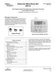
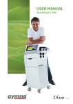
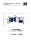
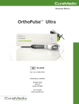
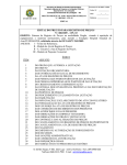
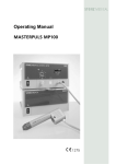
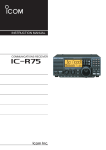
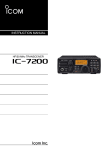
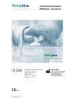
Operating Manual D-200 Published November 2009 Original language: German STORZ MEDICAL AG Lohstampfestr. 8 CH-8274 Tägerwilen Switzerland 14 301 02 1109 20228 Table of Contents Table of Contents 1 General information 1.1 Introduction 1.1.1 Intended use 1.1.2 Contraindications 1.1.3 Side effects 1.2 Symbols 1.3Prerequisites for operating the D-200 1.3.1 Operator 1.3.2 Operator training 1.4Description of controls and functional elements 1.5 Compressed air supply 1-2 1-2 1-3 1-4 1-4 1-5 1-6 1-6 1-6 1-7 1-8 2 Installation instructions 2.1 Unpacking 2.2 Scope of supply 2.3 Installation 2.3.1 Handpiece holder installation 2.3.2Connecting the compressed air supply 2.3.3 Connecting the power supply cables 2.3.4 Handpiece connection 2.3.5 Optional potential equalisation 2-2 2-2 2-2 2-3 2-3 2-4 2-5 2-6 2-7 3 Operation 3.1General warnings and safety information 3.2 Operation 3.2.1 User interface 3.2.2 Overview of menu functions 3.2.3 Starting the instrument 3.2.4 Setting the treatment parameters 3.2.5Storing the treatment parameters 3.2.6 Loading treatment data 3.2.6.1Pre-programmed indications from the manufacturer 3.2.6.2 In-house applications 3.2.6.3 Patient record 3.2.6.4 Printing data* 3.2.6.5 Data transfer 3.2.7 Software updates 3.2.7.1 Loading the software onto the USB stick 3.2.7.2Updating the software on the instrument 3.2.8Resetting the treatment pulse counter 3.2.9Resetting the handpiece pulse counter 3.3 Start-up 3.3.1 Start-up of D-ACTOR mode 3-2 3-2 3-5 3-5 3-9 3-12 3-12 3-13 3-15 3-15 3-17 3-18 3-20 3-21 3-23 3-23 3-25 3-27 3-27 3-28 3-28 14 301 02 1109 Table of Contents 3.3.2 Start-up of V-ACTOR mode 3.4 Functional checks 3.4.1Functional checks in D-ACTOR mode 3.4.2Functional checks in V-ACTOR mode 3.5 Standard settings 3.5.1 Standard settings D-ACTOR mode 3.5.2 Standard settings V-ACTOR mode 3.6 Treatment 3.6.1 Treatment in D-ACTOR mode 3.6.2 Treatment in V-ACTOR mode 3-29 3-30 3-30 3-30 3-31 3-31 3-31 3-32 3-32 3-33 4Cleaning, maintenance, overhaul 4.1 Cleaning 4.1.1Cleaning the optional KARL STORZ foot switch 4.2 D-200 mains fuse replacement 4.3 Maintenance and safety checks 4.4 Disposal 4.5 Repair 4-2 4-2 4-2 4-3 4-4 4-4 4-4 5Status messages and trouble shooting 5.1 Status messages 5.2 Trouble-shooting 5-2 5-2 5-2 6 6.1 6.2 6.3 6.4 Accessories and spare parts D-200 Compressors Accessories Documentation 6-2 6-2 6-2 6-3 6-3 7 7.1 7.2 7.3 Technical specifications D-200 D-200 nameplate Conformity with standards 7-2 7-2 7-3 7-3 8 8.1 8.2 Warranty and service Warranty Service 8-2 8-2 8-2 14 301 02 1109 BLANK PAGE 14 301 02 1109 General information 14 302 02 1109 1 1-1 Chapter 1 – General information 1 General information 1.1 Introduction This manual contains warnings, safety instructions and specific operating instructions in accordance with liability regulations. DANGER Refers to a situation of acute danger which, if not avoided, could lead to serious or fatal injury. WARNING Refers to a situation of potential danger which, if not avoided, could lead to serious or fatal injury. CAUTION Refers to a situation of potential danger which, if not avoided, could lead to minor injury. ATTENTION Warns against possibly harmful situations that could lead to damage to either the product or to the surrounding area. NOTE Additional information concerning specific features or operating instructions is preceded by the term 'NOTE'. 1-2 14 302 02 1109 Chapter 1 – General information CAUTION Before you start using the D-200 for the first time, please make sure you have read and understood all information provided in this operating manual. Familiarity with the information and instructions contained in this manual is essential for being able to operate the instrument quickly and effectively, for avoiding dangers to persons and to the equipment and for obtaining good treatment results. Thorough knowledge of the information included in this manual will also enable you to react promptly and effectively in the event of malfunctions and errors. When using optional accessories, please also refer to the separate operating manuals for each of these accessories. It is imperative that users be familiar with the content of this manual before operating any part of this system. 1.1.1 Intended use The instrument is a compressed air operated pulse activation therapy unit with massage effect. Intended use: - Cellulite - Striae, stretch marks - Lymph congestion - Muscle and connective tissue relaxation NOTE The D-200 is not suitable for treating illnesses. 14 302 02 1109 1-3 Chapter 1 – General information 1.1.2 Contraindications CAUTION The contraindications listed here are examples. No claims are made regarding the completeness or unlimited validity of this list of contraindications. Treatment with the STORZ MEDICAL D-200 is not permitted in the following cases: - Coagulation disorders (haemophilia) - Use of anticoagulants, especially Marcumar - Thrombosis - Tumour diseases, carcinoma patients - Pregnancy - Children in growth - Cortisone therapy up to 6 weeks before first treatment Make sure that all contraindications have been excluded. If you have any doubts, please contact your patient's GP. CAUTION Pressure pulses must not be applied to target areas located above air filled tissue (lungs), nor to any regions near large nerves, vessels, the spinal column or head (except in the facial area). In the case of cosmetic/aesthetic indications, this means that the following areas of the body are not allowed to be treated: Neck, thorax and groin (inner thigh area). 1.1.3 Side effects Treatment with the D-200 may cause the following side effects: - Swelling, reddening, haematomas - Petechiae - Pain - Skin lesions after previous cortisone therapy These side effects generally abate after 5 to 10 days. 1-4 14 302 02 1109 Chapter 1 – General information 1.2 Symbols Operating manual must be observed Please read the operating manual Please comply with the operating manual Degree of protection against electric shocks Potential equalisation D-ACTOR handpiece connection USB connector Ethernet connector CE mark WEEE label 14 302 02 1109 1-5 Chapter 1 – General information 1.3Prerequisites for operating the D-200 1.3.1 Operator The D-200 is exclusively intended for use by cosmetic experts. 1.3.2 Operator training Operators of the D-200 must have been adequately trained in using this system safely and efficiently before they operate the instrument described in this handbook. An introduction to the principles of operation will be provided by your STORZ MEDICAL dealer with reference to this operating manual and will be documented in the system logbook. The operator must be instructed in the following points: - Instruction in operation and designated use of the instrument with practical exercises. - Mode of effect and function of the instrument and the applied energies. - Settings of all components. - Indications for use of the instrument. - Contraindications and side effects of the acoustic waves. - Explanation of warnings in all operating modes. - Instruction in how to perform the functional checks. Further training requirements vary from country to country. It is the operator’s responsibility to ensure that training meets the requirements of all applicable local laws and regulations. Further information on training in the operation of this system is available from your STORZ MEDICAL dealer. You can also contact us directly at the following address: STORZ MEDICAL AG Lohstampfestrasse 8 Postfach CH-8274 Tägerwilen Switzerland 1-6 Tel.: +41 (0) 71 677 45 45 Fax: +41 (0) 71 677 45 05 14 302 02 1109 Chapter 1 – General information 1.4Description of controls and functional elements 1 2 3 Fig. 1 - 1 Front view D-200 1 LCD touch screen 2 Operating indicator 3 D-ACTOR handpiece connectors 1 2 Fig. 1 - 2 Side view D-200 1 Handpiece 2 Handpiece holder 14 302 02 1109 1-7 Chapter 1 – General information 1 2 3 4 5 6 7 Fig. 1 – 3 1 2 3 4 5 6 7 Rear side D-200 Compressed air connector USB connector Mains outlet for jumper cordset (mains outlet for compressor) Mains connector Mains fuse holder Mains switch Potential equalisation connector A second handpiece holder can be mounted on the instrument if required. A holder for a second D-ACTOR handpiece or for a V-Actor (Fig. 1 - 4) can be fitted as required. Each of the two holders can be mounted on the right or the left side of the instrument. Fig. 1 - 4 V-ACTOR holder D-ACTOR holder 1.5 Compressed air supply For the compressed air supply of the D-200 the following compressors are available: - Energy II compressor - Sil.Air 50 TDC compressor 6 1-8 Part. no. see chapter 6 ACCESSORIES AND SPARE PARTS 14 302 02 1109 Installation instructions 14 303 02 1109 2 2-1 Chapter 2 – Installation instructions 2 Installation instructions 2.1 Unpacking •Carefully remove the instrument and accessories from the packaging container. • C heck that all items are included in the packaging container and that they are not damaged. • C ontact your supplier or the manufacturer immediately if any items are missing or damaged. Keep the original packaging. It may prove useful for any later equipment transport. 2.2 Scope of supply The standard scope of supply of the STORZ MEDICAL D-200 includes the following items: - - - - - - 6 2-2 D-200 (control system) D-ACTOR handpiece Complete D-ACTOR handpiece holder Mains cable Gel bottle User manual (operating manual, system logbook and training records) Please refer to chapter 6 ACCESSORIES AND SPARE PARTS for information on optional accessories. 14 303 02 1109 Chapter 2 – Installation instructions 2.3 Installation 2.3.1 Handpiece holder installation • T he D-ACTOR handpiece can be fitted to the right or to the left side of the system as desired by the system user (Fig. 2 - 1/2). Fig. 2 - 1 Location of the bores provided on both side panels • Remove the holder and accessories from the package. • Mount the handpiece holder as shown in Fig. 2 - 2. Fig. 2 - 2 14 303 02 1109 Position of the handpiece holder 2-3 Chapter 2 – Installation instructions 2.3.2Connecting the compressed air supply ATTENTION The compressed air input pressure must be 6.0 - 7.0 bar. If compressors other than the STORZ MEDICAL ENERGY compressor are used, this pressure must be checked on the compressed air supply system. If the pressure exceeds 7.5 bar, the instrument’s overpressure protection will be tripped. The compressed air must be dry, oil-free and filtered to < 5µm. Never use CO2 and O2 gas for compressed air supply. If compressed air is supplied through a wall outlet, use a pressure reducer (max. 7 bar), if necessary. •Place the respective compressor onto a solid and stable surface. Set up the units next to one another. •Connect the compressed air tube to the compressed air connectors provided on the compressor. •Connect the compressed air tube to the compressed air tube connector provided on the rear side of the D-200 until it audibly engages (Fig. 2 - 3). Fig. 2 – 3 Compressed air connectors on the D-200 ATTENTION When setting up the instrument, make sure that the air outlets on the housing of the D-200 are not blocked. 2-4 14 303 02 1109 Chapter 2 – Installation instructions 2.3.3 Connecting the power supply cables The external ENERGY II compressor can be controlled by the D-200 via the mains power link cable. •Connect the ENERGY II compressor via the mains power link cable to the D-200 (use connector shown in Fig. 2 - 4/1). • C onnect the D-200 via the mains cable to the mains connector (Fig. 2 - 4/2). 1 Fig. 2 – 4 2 Connecting the power supply cables NOTE The compressor is automatically switched on and off with the D-200. During first installation, make sure that the mains switch of the compressor is in ON position. ATTENTION Please comply with the maximum permitted connection values of the mains power link cable (see chapter 7 TECHNICAL SPECIFICATIONS). 14 303 02 1109 7 2-5 Chapter 2 – Installation instructions 2.3.4 Handpiece connection •Connect the connector of the D-ACTOR handpiece to one of the handpiece connectors (Fig. 2 - 5/1) provided on the D-200. 1 Fig. 2 – 5 • M ake sure that the red spots on the connector match the red spots on the handpiece connector. Fig. 2 – 6 Handpiece connector Connecting the handpiece • Place the handpiece in the handpiece holder. NOTE Please refer to the separate operating manual of the handpiece. 2-6 14 303 02 1109 Chapter 2 – Installation instructions 2.3.5 Optional potential equalisation The D-200 features a potential equalisation connector (Fig. 2 - 7/2). • C onnect one end of the potential equalisation cable to the PE connector of the D-200 and the other end to your PE connection. 1 Fig. 2 – 7 2 Potential equalisation CAUTION The potential equalisation connector of the D-200 must be connected in accordance with the relevant national regulations. 14 303 02 1109 2-7 BLANK PAGE 2-8 14 303 02 1109 Operation 14 304 02 1109 3 3-1 Chapter 3 – Operation 3 Operation 3.1General warnings and safety information CAUTION 1.3 The D-200 is exclusively intended for use by cosmetic experts (see chapter 1.3 PREREQUISITES FOR OPERATING THE D-200). The user is responsible for correctly positioning the handpiece of the D-200. Correct determination of the location of the treatment zone is the responsibility of the user. Only perform treatments approved by STORZ MEDICAL AG! 1.1.1 To avoid safety hazards, use of the instrument for applications other than those specified in chapter 1.1.1 INDICATIONS is not allowed! Only the ENERGY ll compressor is allowed to be connected to the mains outlet for jumper cordset (mains outlet for compressor) (Fig. 1 - 3/3). The D-200 has a potential equalisation connector. This must be connected in accordance with the relevant national regulations. Do not use the D-200 in potentially explosive environments, i.e. in the presence of a flammable anaesthetic mixture with air or with oxygen or nitrous oxide. Cleaning agents and disinfectants can form an explosive atmosphere. Disconnect the mains plug before starting any cleaning and maintenance work on the D-200! Before any cleaning and maintenance work on the handpiece, disconnect the handpiece plug from the handpiece connector! Do not connect the handpiece until it has been completely reassembled! Do not try to open the instrument! Risk of electric shocks! 4 3-2 Risk of transmission of microorganisms! Disinfect the handpiece after each treatment! Also refer to chapter 4 CLEANING for details. 14 304 02 1109 Chapter 3 – Operation ATTENTION Check that the installation surfaces have sufficient carrying capacity to avoid equipment damage! Portable and mobile HF communications equipment (e.g. mobile phones) can interfere with electrical equipment. The use of accessories or cables that are not authorised by the manufacturer can result in increased interference emissions or reduced resistance to interference emissions by the instrument. The D-200 must neither be deployed nor stored together with other devices. If the operation near or jointly with other devices is required, the D-200 has to be tested against that particular environment to ensure operation according to technical specification. The D-200 may be deployed and operated close to the listed accessories. The instrument must only be connected to properly earthed and correctly installed pulseproof sockets! Check that the instrument is in perfect working order before each use, see chapter 3.4 FUNCTIONAL CHECKS. 3.4 Never cover the instruments when in use! Make absolutely sure that no liquid can seep into the system housing or handpiece. Any damage to the unit resulting from incorrect operation is not covered by the manufacturer’s warranty. Disposal of the instrument and its components must be carried out in accordance with national waste disposal regulations. The D-200 must only be used with accessories that have been approved by the system manufacturer. For safety reasons, unauthorised instrument modifications are not permitted. This will void the CE mark approval and warranty. 14 304 02 1109 3-3 Chapter 3 – Operation NOTE The D-200 meets the requirements of the applicable electromagnetic compatibility (EMC) standards EN 60601-1-2. These requirements are defined to provide reasonable protection against harmful interference. The instrument described here generates and uses high-frequency energy and can emit the same. If not installed and used in accordance with these instructions, the equipment may cause harmful interference to other devices in the vicinity. However, there is no guarantee that interference will not occur in a particular installation. If the product described here does cause harmful interference with other devices in the vicinity, which can be determined by turning the equipment off and on, the user is encouraged to try to correct the interference by one or more of the following measures: - Reorient or relocate the receiving device - Increase the distance between the devices -Connect the devices into an outlet on a circuit different from that to which the other device is connected - 3-4 Consult the manufacturer or field service technician for help 14 304 02 1109 Chapter 3 – Operation 3.2 Operation The D-200 is operated using a colour TFT LCD monitor with touch screen function and a graphical user interface. 3.2.1 User interface The user interface of the D-200 is divided into various areas for displaying different information. The individual controls are arranged in function groups (Fig. 3 - 1): 2 1 Control buttons Control buttons 3 4 9 5 8 Control buttons Control buttons 6 7 Fig. 3 - 1 1 - 3 4 5 6-8 9 Controls Top navigation bar Status bar Selection area Bottom navigation bar Parameter display (nominal and actual values) NOTE The following functional description refers to control software version 13441.13.1.0 or higher. 14 304 02 1109 3-5 Chapter 3 – Operation Navigation bars: The top and bottom navigation bars (Figs. 3 - 1/1 to 3 - 1/3 and 3 - 1/6 to 3 - 1/8) contain control buttons that you can use for navigating through the menus: Parameter entry screen: Not active Open the sub-menu Jump to the “Load configuration” sub-menu (call up saved parameter configurations or patient records) Main and sub-menu: Step back Return to parameter entry screen Delete configurations Save configurations Confirm entries, acknowledge messages The arrow keys can be used for changing (increasing or decreasing) the parameter values. If you are in a sub-menu that contains more menu items than can be displayed in the viewing area, you can use the arrow keys for scrolling to the foot of the list. Touching the date key on the parameter entry screen will open the "Info" window. A display on the left of the status bar (Fig. 3 - 1/4) shows which operating mode is active. The flag on the right of the status bar displays the menu language. Touching the flag symbol takes you directly to the "Languages" sub-menu where you can select a different menu language. A warning symbol appears at the far left of the status bar if there is an error. Touching this symbol takes you directly to the "Warnings" sub-menu that displays all warning messages that are currently active. The name of the loaded configuration (*indication/ patient name) appears in the centre of the status bar. 3-6 14 304 02 1109 Chapter 3 – Operation Parameter display: The treatment parameters are displayed in the parameter display field (Fig. 3 - 1/9) in the following sequence: D-ACTOR Nominal energy level in bar Nominal number of pulses Nominal frequency Actual number of pulses After the first start-up of the unit as well as after configuration loading, the display flashes and must be confirmed by touching the display field or a parameter. Selection area: - The selection area (Fig. 3 - 2) of the parameter entry screen contains the nominal value selection fields “Energy”, “Number of pulses” and “Frequency” and an additional operating mode display (shown as text and a symbol). Fig. 3 - 2 Parameter entry screen 14 304 02 1109 3-7 Chapter 3 – Operation - When you open a menu, the name of the opened menu appears in the top line against a dark blue background. The sub-menu items are indented (Fig. 3 - 3). - A sub-menu item is selected by touching the corresponding display area. - The selected sub-menu item appears against a dark blue background. - Sub-menu items that themselves have an additional sub-menu are identified by a green arrow to the right (Fig. 3 - 3/2). - If there are more than 4 menu items, they can be selected using the arrow keys (Fig. 3 - 3/1). If one of the arrow keys disappears, this means no more selections can be made in this direction. - Once a sub-menu has been selected, it is opened using the "OK" button. 1 Fig. 3 - 3 3-8 2 List of sub-menu items 14 304 02 1109 Chapter 3 – Operation 3.2.2 Overview of menu functions Parameter entry screen Main menu 1st sub-menu 2nd sub-menu Save configuration Save configuration Keyboard Load configuration Load configuration Keyboard Menu Actual val. reset Warnings Print Print Data transfer Data transfer Setup Setup Info Language Language Time Touch-screen calibration Reset handpiece holder Warning history Software update Service (HW enable) Fig. 3 - 4 14 304 02 1109 Service Menu overview 3-9 Chapter 3 – Operation Parameter entry screen - Determining the treatment parameters Main menu Reset counter - R esetting the actual values in the selected operating mode (treatment pulse counter, total energy, close patient record) Save configuration - S aving indication-specific (preceded by *) or patient-specific treatment parameters Load configuration - L oading already stored treatment parameters, opening the patient's treatment protocol. The keyboard window in the 2nd sub-menu enables you to make your own text entries. However, you can also do this by connecting a separate USB keyboard (USB connection see Fig. 2 - 8/3). Warnings - List of current warnings Print - T he following reports can be printed using a CL3-capable printer with USB port connection: 1. Configuration report 2. Warnings report 3. Treatment protocol Data transfer - E xport treatment data (using this sub-menu, it is possible to transfer the treatment data as files onto a USB memory stick and open them in Excel) - Backup settings (backup) - Restore settings (backup) 1st sub-menu 3-10 Setup See 1st sub-menu Info - T otal pulse count and operating hours of the instrument (depending on operating mode selected) - Total pulse count of the handpiece in question, data on software, operating system and hardware serial numbers - Information about modules: to view serial numbers and indexes of the modules scroll to the second page of the Info window by using the arrow key. 14 304 02 1109 Chapter 3 – Operation Warning history - List of the last 100 warning and error messages Language - Setting the language Time - Setting the date and time Touch-screen calibration - T his function makes it possible to recalibrate the touch screen, i.e. for correct recognition of the touch coordinates Software update - T ransferring a software update from the USB memory stick Set pulse number/ total energy 14 304 02 1109 - C hangeover between pulse count and total energy nominal value specification 3-11 Chapter 3 – Operation 3.2.3 Starting the instrument • Switch the D-200 and the connected compressor on using the master switch. Once the unit has been started, the display automatically shows the last setting. The display is flashing. • T ouch the flashing parameter field or one of the parameter selection fields to confirm the operating parameters. • F ollow the instructions in chapter 3.2.4 SETTING THE TREATMENT PARAMETERS to change the operating parameters. 3.2.4 Setting the treatment parameters • S elect the line of the parameter that you would like to change (Fig. 3 - 4). The selected line is highlighted dark blue. • Increase or decrease the value using the arrow keys (Fig. 3 - 4/1). 1 2 Fig. 3 - 4 Setting the treatment parameters The pulse frequency can be selected in steps from 0.5 Hz respectively 1 Hz to 21 Hz with energy levels of 1.0 to 5.0 bar. 3-12 • F rom version 13441.13.1.0 onwards, touching the trigger button makes it possible to switch to the corresponding operating mode of the handpiece. • T he operating parameters are set and saved separately for each handpiece (connector). • The V-ACTOR handpiece has independent setting options. 14 304 02 1109 Chapter 3 – Operation 3.2.5Storing the treatment parameters • Touch the “Menu” button. • Select the “Save configuration” function (Fig. 3 - 5/1) to save the current setting of the treatment parameters. • Touch the “OK” button. 1 2 Fig. 3 - 5 Storing the treatment parameters A list with a total of 100 memory locations appears on the touch screen display in the “Save configuration” sub-menu. The system automatically stores the new parameter configurations at the end of the list with the corresponding creation date and time (Fig. 3 - 6/1). • Touch the "Save" key to save the current setting (Fig. 3 - 6/2). 1 3 Fig. 3 - 6 14 304 02 1109 2 Sub-menu “Save configuration” 3-13 Chapter 3 – Operation NOTE If you select a field that is already occupied, you are asked if you want to overwrite the content. Confirm with "OK" or revoke your selection by touching the "Back" button. • To rename the configuration, touch the button again that has already been selected (Fig. 3 - 6/1). This activates the keyboard window (Fig. 3 - 7).* * Text can also be entered using an external USB keyboard. Connect the keyboard to the D-200 USB connector (Fig. 2 - 7/1). Fig. 3 - 7 Keyboard window You can save your parameter setting either under the name of an indication or under a patient’s name. • To save the parameters as an indication, place an “*” before the name of the indication or leave it in place (“*Indication name”). The saved and selected or loaded indication appears in the status bar. This display goes out again if the value range recommended for this indication is changed. • To save the parameters for a particular patient (patient record), store the setting directly under the name of the patient (“name, first name”). The configuration stored for a patient name is also displayed in the status bar. The display of patients’ names does not disappear when the parameters are changed. All parameter changes are logged in a table. The patient record is closed when: - a new patient record is called up (loaded), - an indication is loaded, - a parameter reset is performed (actual value), - the unit is switched off. • Confirm each of your entries with the “OK” button. • Delete a stored configuration that is no longer required using the “Delete” button (Fig. 3 - 6/3). Up to 1000 treatments can be stored. 3-14 14 304 02 1109 Chapter 3 – Operation 3.2.6 Loading treatment data The list of treatment parameters already stored or of the patient record can be opened either directly from the parameter entry screen or from the main menu screen. • If you are on the parameter entry screen, touch the “Configuration” button (Fig. 3 - 4/2). • If you are in the main menu, select the “Load configuration” function from the list (Fig. 3 - 5/2). The menu "Load configuration" contains the following indication groups: - In-house applications - Aesthetic indications 3.2.6.1Pre-programmed indications from the manufacturer • Select an indication or a patient from the list. • Touch the “OK” button. Fig. 3 - 8 Loading a configuration I • Select the required indication. Fig. 3 - 9 14 304 02 1109 Loading a configuration II 3-15 Chapter 3 – Operation Prior to loading an indication, you can view further information on the selected indication. • To accomplish this, touch “Note”. The treatment notes will be displayed. To load the indication, touch “Back” to return to the previous screen (Fig. 3 - 9). • Touch “Load”. The indication has been loaded successfully when the loaded indication is displayed on the grey status bar (Fig. 3 - 10). Fig. 3 - 10 Loaded indication •To review the treatment notes, touch the name of the indication on the grey status bar. The loaded indication is exited by - Opening a new indication - Exiting the treatment parameters screen - Switching off the instrument - Switching to a different operating mode - Touching 3-16 14 304 02 1109 Chapter 3 – Operation 3.2.6.2 In-house applications • Touch the “In-house applications” button (Fig. 3 - 11). • Touch “OK”. Fig. 3 - 11 In-house applications • Touch the button for the indication required (Fig. 3 - 12). Fig. 3 - 12 In-house indications If additional information for the selected indication has been saved, this can be accessed by touching “Note” (Fig. 3 - 12). 1 Fig. 3 - 13 Text box for treatment notes •To add additional information, touch the text field (Fig. 3 - 13/1) to display the on-screen keyboard. • Save the text by touching “OK”. 14 304 02 1109 3-17 Chapter 3 – Operation •Touch the “Back” button to view the list of in-house applications. • Touch the “Load” button. The highlighted indication will be loaded. The indication has been loaded successfully when the loaded indication is displayed on the grey status bar. •To review the treatment notes, touch the grey status bar. The loaded indication is exited by - Opening a new indication - Exiting the treatment parameters screen - Switching off the instrument - Switching to a different operating mode 3.2.6.3 Patient record • Touch the “In-house applications” button (Fig. 3 - 11). • Touch “OK”. •Touch the button on which the required patient name is displayed (Fig. 3 - 14). Fig. 3 - 14 Loading a patient record • Touch the “Protocol” button. The patient record will be displayed. Fig. 3 - 15 3-18 Patient record – treatment details 14 304 02 1109 Chapter 3 – Operation A patient record consists of treatment details (Fig. 3 - 15) and a table of treatment parameters that is created by the instrument automatically (Fig. 3 - 16). Each time a patient is accessed, a new treatment with the current date is saved to his or her patient record. Fig. 3 - 16 Treatment parameters •To add additional treatment details, touch the text fields (Fig. 3 - 13/1) to display the on-screen keyboard. • Save the text by touching “OK”. •Touch the “Back” button to view the list of in-house applications. • Touch the “Load” button. The treatment parameters for the highlighted patient will be loaded. The treatment parameters have been loaded successfully when the patient’s name is displayed on the grey status bar on the protocol screen (Fig. 3 - 15). •To review the patient record, touch the grey status bar. The patient record is closed by - Opening a new patient record or indication - Resetting the pulse counter - Switching off the instrument 14 304 02 1109 3-19 Chapter 3 – Operation 3.2.6.4 Printing data* • Connect a printer with USB interface connection to the USB socket on the rear of the D-200. Printing treatment data • Load an indication. • Select the “Print” / “Configuration report” function in the 1st sub-menu (Fig. 3 - 15/1). 1 2 3 Fig. 3 - 15 Printing data The indication or the treatment parameters is/are printed. If no indication is opened then all treatment parameters are printed. Printing a patient record • Load a patient data record. • Select the “Print” / “Treatment protocol” function in the 1st sub-menu (Fig. 3 - 15/3). The patient record is printed. If no patient-specific parameter record is opened then all patient-specific data is printed. Printing a warnings report • Select the “Print” / “Warnings report” function to print the list of errors that have occurred (Fig. 3 - 15/2). The warnings report is printed. * The “Print data” function can only be used with a CPL3-capable printer complying with the IEC 60601-1 standard. 3-20 14 304 02 1109 Chapter 3 – Operation 3.2.6.5 Data transfer Using this function, treatment data can be exported onto a USB memory stick in a format that can be opened in Excel. Also, operating data can be saved (backup) or restored following a repair or if the instrument is replaced. • Ensure that your USB memory stick supports the USB V1.1 protocol. You can order a validated USB stick from your dealer. Exporting treatment data • Load a patient-specific parameter record. • Select the “Data transfer” / “Export treatment data” function in the 1st sub-menu (Fig. 3 - 16/1). 1 2 3 Fig. 3 - 16 Data export • Connect the memory stick to the USB connector as soon as you are prompted to do so (Fig. 3 - 17) and confirm with “OK”. Fig. 3 - 17 Data export The USB connection is established (Fig. 3 - 18). 14 304 02 1109 3-21 Chapter 3 – Operation Fig. 3 - 18 Establishing the USB connection The data is transferred once the USB connection has been established. The export file name of the patient record is protocol_name.csv. All data is exported if no patient record or no indication has been opened. The export file name of the record data is protocol_DateTime.csv. • Wait until the “Export completed” message appears on the display (Fig. 3 - 19), then remove the memory stick. Fig. 3 - 19 Data export complete Backing up the settings Using the “Backup settings” function, you can save configuration settings, patient and indication data onto a USB memory stick as a backup (in a file format that can only be read by the instrument). • Select the “Data transfer” / “Backup settings” function in the 1st sub-menu (Fig. 3 - 16/2). • Connect the memory stick to the USB connector as soon as you are prompted to do so (Fig. 3 - 17) and confirm with “OK”. After the USB connection has been established, the data backup is performed and the text window shows the name of the backup file. • Remove the USB memory stick. 3-22 14 304 02 1109 Chapter 3 – Operation Restoring the settings The system is restored to the data status of the last backup using the “Restore settings” function. • Select the “Data transfer” / “Restore settings” function in the 1st sub-menu (Fig. 3 - 16/3). • Connect the memory stick with the backup file to the USB connector as soon as you are prompted to do so (Fig. 3 - 17) and confirm with “OK”. After establishing the USB connection, the system is uploading the backup data file. Upon completion of the upload, the system has to be re-started. • Remove the USB stick and restart the system. 3.2.7 Software updates 3.2.7.1 Loading the software onto the USB stick 3.2.7.1.1 Extracting the software using Windows XP • Save the ZIP file onto your computer’s hard disk. • Right-click on the ZIP folder symbol. • In the shortcut menu, select “Explorer” (Fig. 3 - 20). Fig. 3 - 20 Selecting “Explorer” The folder with the update files appears on the left of the window (Fig. 3 - 21). 14 304 02 1109 3-23 Chapter 3 – Operation Fig. 3 - 21 Folder with update files • In this folder, select the “combiselect_update.ini” and “combiselect_update_img.ini” files and the “ffsdisk” folder (Fig. 3 - 21) and copy both of them onto your USB stick. • Start the software update as described in chapter 3.2.7.2. 3.2.7.1.2 • Connect the USB stick to your computer. • Save the ZIP file onto the USB stick (Fig. 3 - 22). Fig. 3 - 22 Zip file saved on USB stick • Right-click on the ZIP file symbol. • In the shortcut menu, select the WinZip symbol (Fig. 3 - 23). • Select "Extract here“ (Fig. 3 - 23). Fig. 3 - 23 3-24 Extracting the software with WinZip Extracting files 14 304 02 1109 Chapter 3 – Operation • F ollowing extraction, the following files are displayed on the USB stick: “combiselect_update.ini”, “combiselect_update_img.ini” and “ffsdisk” folder (Fig. 3 - 24). Fig. 3 - 24 Files have been extracted • R emove the USB stick and start the software update as described in chapter 3.2.7.2. 3.2.7.2Updating the software on the instrument • Select the “Update software” function in the “Setup” menu. • C onnect the USB stick to the USB connector of the D-200 as soon as you are prompted to do so (Fig. 3 - 25) and confirm with “OK”. Fig. 3 - 25 Software update The software update is performed once the USB connection has been established. • W ait until the update has been completed, then restart the instrument (Fig. 3 - 26). Fig. 3 - 26 14 304 02 1109 Installation completed (step 1 of 2) 3-25 Chapter 3 – Operation After restarting, you will be prompted to reinsert the USB stick. • Make sure that the USB stick is inserted and touch “OK”. The instrument now offers the possibility to load the Chinese character set or treatment images (Fig. 3 - 27). Fig. 3 - 27 Selecting an option • Select one of the two options and confirm with "OK". • Following the restart prompt, please restart the instrument. After the restart, the selected option will be loaded. • Open the Info window by touching the "Date" button. • Check that the Info window is displaying the current software version. Fig. 3 - 28 Installation completed (step 2 of 2) • Remove the USB stick. The instrument is ready for use. 3-26 14 304 02 1109 Chapter 3 – Operation 3.2.8Resetting the treatment pulse counter • To reset the applied pulses counter to ‘0’, select the “Actual val. reset” menu option (Fig. 3 - 29) or touch the counter display directly (Fig. 3 - 29/1). 3.2.3 1 Fig. 3 - 29 Resetting the treatment pulse counter 3.2.9Resetting the handpiece pulse counter To register the number of pulses triggered following a handpiece inspection (renewal of projectile and tube), it is possible to reset the handpiece counter for D-ACTOR mode. • Select the D-ACTOR operating mode. • Touch the “Menu” button in the main menu. •Select the “Reset handpiece counter” function in the “Setup” menu. • Confirm the following text message (Fig. 3 - 30) with “OK”. Fig. 3 - 30 Handpiece pulse counter reset The handpiece pulse counter is set to zero. NOTE The internal instrument counter is not reset. 14 304 02 1109 3-27 Chapter 3 – Operation 3.3 Start-up Switch the instrument on as described in chapter 3.2.3 STARTING THE INSTRUMENT. 3.3.1 Start-up of D-ACTOR mode NOTE Prior to start-up please refer to the separate operating manual of the handpiece and your compressor. • Set the energy of the pulses to an initial value of 2 bar. The maximum pressure is limited to 5.0 bar. The minimum pressure that can be set is 1.0 bar. • Press the D-ACTOR trigger button. The D-ACTOR handpiece can be operated in single pulse mode and in continuous pulse mode. • To work in D-ACTOR single pulse mode, select the “-” symbol (dash) in the “Frequency” selection box and activate the trigger button. • To work in D-ACTOR continuous pulse mode, select a continuous pulse frequency in the range from 0.5 to 21 Hz in the “Frequency” selection box. • Activate the trigger button. NOTE A window with the following text appears if the set nominal pulse value (e.g. 400 pulses) is reached during treatment: “number/energy set value reached”. The message can be acknowledged with the “OK” button or the corresponding trigger button. Further treatment is possible. This message is activated again as soon as a multiple of the set nominal value is reached (e.g. 800 pulses, 1200 pulses, etc.). 3-28 14 304 02 1109 Chapter 3 – Operation 3.3.2 Start-up of V-ACTOR mode The V-ACTOR handpiece is available as an optional accessory for the instrument. NOTE During start-up, also follow the instructions in the separate operating manual for your V-ACTOR handpiece. • Connect the V-ACTOR handpiece to the control unit. • Set the energy of the pulses in V-ACTOR operating mode to an initial value of 2 bar. • Press the V-ACTOR trigger button. NOTE Pressing the trigger button briefly causes it to function as an on/off switch. Pressing it for longer causes it to function as a tip switch, i.e. the pulses will be triggered until the button is released. 14 304 02 1109 3-29 Chapter 3 – Operation 3.4 Functional checks Perform the following functional checks after the system has been installed: • Check the control unit and handpieces for damage. • Start the D-200 (see chapter 3.3. START-UP). 3.4.1Functional checks in D-ACTOR mode • Set the energy level in D-ACTOR mode to 2 bar. •Reset the actual number of pulses on the parameter display of the control panel (see chapter 3.2.8 RESETTING THE TREATMENT PULSE COUNTER). • Release individual pulses in single pulse mode. •Release the pulses in continuous pulse mode (pulse frequency 5 Hz/15 Hz). • Release pulses by means of the foot switch, if used. •Check that the triggered pulses are correctly counted on the treatment pulse counter. 3.4.2Functional checks in V-ACTOR mode 3-30 • Set the energy level in V-ACTOR mode to 2.4 bar. • R eset the actual pulse count on the parameter display of the control panel. • Release pulses with a pulse frequency of 30 Hz. • Release pulses by means of the foot switch, if used. • C heck that the triggered pulses are correctly counted on the treatment pulse counter of the control unit. 14 304 02 1109 Chapter 3 – Operation 3.5 Standard settings •Before each treatment, make sure that the number of pulses and the actual energy value are set to zero (see chapter 3.2.8 RESETTING THE TREATMENT PULSE COUNTER). NOTE Set the nominal value counter to the required value. The “-” symbol appears if zero is selected. The instrument then operates without a nominal value specification. 3.5.1 Standard settings D-ACTOR mode •Start the D-ACTOR treatment at a pressure of 2 bar and a frequency of 5 Hz. 3.5.2 Standard settings V-ACTOR mode •Start the V-ACTOR treatment at an energy level of 2 bar and a frequency of 20 Hz. •For more detailed instructions, refer to the application brochure / treatment recommendations. 14 304 02 1109 3-31 Chapter 3 – Operation 3.6 Treatment CAUTION Read chapter 3.1 SAFETY INSTRUCTIONS before beginning the treatment. Please also follow the instructions in the separate operating manual for your handpiece. Each time after the instrument has been transported, make sure that all functional checks have been performed on the unit before you start treatment. Only perform treatments approved by STORZ MEDICAL AG! To avoid safety hazards, use of the system for applications other than those specified in chapter 1.1.1 INDICATIONS is not allowed! All status and error messages signaled during treatment must always be attended to without delay! The maximum energy level used during treatment must not cause the patient undue pain under any circumstances. 3.6.1 Treatment in D-ACTOR mode •Apply a sufficient amount of coupling gel to the patient’s skin in the coupling area and to the pulse activator. •Perform the D-ACTOR treatment as described in the D-200 application brochure or using the treatment parameters stored in the system (see also the information in the concise instructions supplied). CAUTION The pulse activator surface will become hot! Extended skin contact can lead to minor burns! • Interrupt treatment after a maximum of 6000 pulses. 3-32 14 304 02 1109 Chapter 3 – Operation •Do not apply more than 300-400 pulses to the same spot. • A void excessive pressure of the pulse activator to patient's skin. Such pressure is not needed for successful treatment. 3.6.2 Treatment in V-ACTOR mode •Apply a sufficient amount of massage oil to the part of the patient’s body to be treated and to the V-ACTOR pulse activator. •Perform the V-ACTOR treatment as recommended in the application brochure / treatment recommendations. 14 304 02 1109 3-33 BLANK PAGE 3-34 14 304 02 1109 Cleaning, maintenance, overhaul 14 305 02 1109 4 4-1 Chapter 4 – Cleaning, maintenance, overhaul 4Cleaning, maintenance, overhaul 4.1 Cleaning Regular cleaning of the system ensures perfect hygiene and operation of the D-200. CAUTION Disconnect the instrument from the mains before starting any cleaning or overhaul work! •Wipe the exterior of the housing with a damp cloth. Use soapy water or a mild cleaning agent. ATTENTION It is essential that no fluid be permitted to penetrate either the unit or its tubing. NOTE Please refer to the separate operating manual of the handpiece for information about cleaning and overhauling your handpiece. 4.1.1Cleaning the optional KARL STORZ foot switch • C lean the KARL STORZ foot switch with soapy water or a mild cleaning agent. NOTE The foot switch is protected against ingress of water following classification IPX8 in acc. with IEC 529. 4-2 14 305 02 1109 Chapter 4 – Cleaning, maintenance, overhaul 4.2 D-200 mains fuse replacement The mains fuse holder is located on the rear of the D-200 (see Fig. 4 - 1/1). • P ush the clip of the mains fuse holder (Fig. 4 - 1/1) to the left and take the holder off the housing. 1 Fig. 4 - 1 Mains fuse holder • Pull the old fuses out of the mains fuse holder (Fig. 4 - 2/1). 1 Fig. 4 - 2 Mains fuse replacement • Replace the fuses. • Use type T5AT fuses. • Push the mains fuse holder back into the opening until it engages. 14 305 02 1109 4-3 Chapter 4 – Cleaning, maintenance, overhaul 4.3 Maintenance and safety checks 3.4 Preventive maintenance is not necessarily required. However, regular maintenance may help to identify possible defects at an early stage and thus increase the safety and service life of the equipment. Information on maintenance services can be obtained from our regional representatives in your area or directly from STORZ MEDICAL AG. We recommend that a functional check (see chapter 3.4 FUNCTIONAL CHECKS) and safety checks be performed at least once a year. National accident prevention regulations and test and inspection intervals prescribed for cosmetic devices must, of course, be observed. NOTE For further details on content and performance of the safety checks, please contact your local dealer. Perform the following tests in order to ensure perfect functioning of the D-200 and the optional ENERGY II compressor. 1. Earth leakage current test from chassis according to national regulations. 2. Earth impedance test (with mains cable, incl. applicator housing) according to national regulations. For additional information on maintenance of the Sil.Air 50 TDC compressor, please refer to the separate operating manual. 4.4 Disposal When disposing of the present products, no special measures have to be observed. Please proceed in accordance with the national regulations. After expiration of its service life, dispose of the D-200 as electronic waste. For additional information about the disposal of the Sil.Air 50 TDC compressor, please refer to the separate operating manual. 4.5 Repair Repair work on defective instruments must only be carried out by personnel suitably authorised by STORZ MEDICAL. Only original STORZ MEDICAL spare parts may be used for this purpose. 4-4 14 305 02 1109 Status messages and trouble-shooting 14 306 02 1109 5 5-1 Chapter 5 – Trouble-shooting 5Status messages and trouble-shooting 5.1 Status messages Set pulse number reached Acknowledge message, further treatment is possible. Internal communication error Restart the instrument. If the fault persists, inform your service centre. Printer not ready Connect and switch on the printer. Remove the USB stick, then switch off and restart the instrument. Reinsert the USB stick. USB stick was not recognized Check that there is software on the USB stick. If the fault persists, check that the USB stick supports the USB V1.1 protocol. If it does not, replace the USB stick. 5.2 Trouble-shooting  CAUTION Disconnect the instrument from the mains before you carry out any maintenance work! Fault description Possible cause Corrective actions Instrument does not work Power failure Check the power supply Defective mains fuse Replace the fuses Defective mains plug Replace the mains cable No compressed air supply 5-2 Defective foot switch connecting cable Check the connecting cable and change the foot switch if necessary Leaks on handpiece cable or cable not properly connected Check the connecting cable and change the handpiece if necessary 14 306 02 1109 Chapter 5 – Trouble-shooting Fault description Possible cause Corrective actions No compressed air supply Compressed air tube to compressor not connected or not correctly fastened Check the compressed air tube connection to the compressor Clogged compressor air Check the compressor filter air filter and replace it, if necessary No D-ACTOR power output Blocked or worn projectile Dismantle D-ACTOR handpiece Clean the guide tube and projectile Overhaul the handpiece (see chapter 4 CLEANING, MAINTENANCE, OVERHAUL in the separate D-ACTOR handpiece operating manual) Overhaul the handpiece 2 projectiles in the handpiece Dismantle the D-ACTOR handpiece and remove the excess projectile Handpiece defective Overhaul the handpiece Replace the handpiece No V-ACTOR power output No power output at both handpieces 14 306 02 1109 Pulse activator is not attached to the handpiece correctly Unscrew the pulse activator screw cap and check whether the pulse activator head can be moved up and down, and is not inserted at an angle Handpiece defective Replace the handpiece No compressed air supply Check the compressed air supply Control unit malfunction Contact your service centre 5-3 BLANK PAGE 5-4 14 306 02 1109 Accessories and spare parts 14 307 02 1109 6 6-1 Chapter 6 – Accessories and spare parts 6 Accessories and spare parts 6.1 D-200 Compressed air tube Compressed air tube for compressor, 1 m long 13463 Compressed air tube for compressor, 3 m long 13447 Compressed air tube for central compressed air supply 13464 Mains cable Mains cable CEE 7 Europe, 4 m long (for control unit or ENERGY compressor) 13455 Mains cable CH 3 m 13448 Mains cable USA 3 m 16441 IEC coupling, 1 m long (between control unit and compressor) 13546 NOTE For information on the D-ACTOR handpiece and its accessories, please refer to the separate operating manual of the D-ACTOR handpiece. 6.2 Compressors Energy compressor Energy ll compressor 220-230 VAC blue 17928 Energy ll compressor 115 VAC blue 17976 Energy ll compressor 100 VAC blue 18170 Energy ll compressor 220-230 VAC silver 19573 Energy ll compressor 115 VAC silver 19574 Energy ll compressor 100 VAC silver 19575 Sil.AIR 50 TDC compressor Sil.AIR 50 TDC compressor 230 VAC 6-2 14588 14 307 02 1109 Chapter 6 – Accessories and spare parts 6.3 Accessories Gel bottle 18189 Transport case for ENERGY II compressor 18324 D-200 transport case for control unit and accessories 17415 Transport case for ENERGY II compressor, D-200 and accessories 18460 R-SW handpiece set 18800 V-ACTOR handpiece set 18453 R-SW handpiece holder 18051 V-ACTOR handpiece holder 18825 Trolley for D-200 with Energy II 20402 Trolley for D-200 with SilAir compressor 20433 6.4 Documentation D-200 user manual 14 307 02 1109 20228 6-3 BLANK PAGE 6-4 14 307 02 1109 Technical specifications 14 308 02 1109 7 7-1 Chapter 7 – Technical specifications 7 Technical specifications 7.1 D-200 Operating mode D-ACTOR D-ACTOR: single pulse, continuous pulse 1 - 21 Hz Energy selection D-ACTOR steps of 0.2 bar ranging from 1 to 5.0 bar Mains input voltage Mains frequency Mains fuse Mains power link cable Power consumption with auxiliary device 50 / 60 Hz 5 A T / 250 VAC 100 - 240 VAC / 5 A max. 500 VA Compressed air supply 6 - 7 bar Compressed air output 1 - 5 bar Ambient temperature operation 10° – 40°C Ambient temperature storage and transport 0° – 60°C (frost-free) Ambient air pressure 500 - 1060 hPa Air humidity Control unit weight Housing dimensions (W x H x D) Protection against ingress of water 7-2 100 - 240 VAC 5 – 90%, non-condensing 6.5 kg 340 x 165 x 340 mm IPX1 14 308 02 1109 Chapter 7 – Technical specifications 7.2 D-200 nameplate 7.3 Conformity with standards According to EN 60601-1 - Type of protection against electric shocks: Protection class 1 - Degree of protection against electric shocks: 14 308 02 1109 7-3 Chapter 7 – Technical specifications EMC guidelines and declaration by the manufacturer Guidelines and declaration by the manufacturer – Emitted electromagnetic interference The D-200 model is intended to be used in the electromagnetic environment specified below. The customer or the user of the D-200 should ensure that it is used in such an environment. Emitted interference measurements Compliance Electromagnetic environment – Guidelines Group 1 The D-200 uses HF energy only for its internal function. Therefore, its emitted HF interference is very low, and it is improbable that electronic devices in the immediate vicinity would be disrupted. In accordance with EN IEC 60601-2-36:1997 section 36, this information does not apply to the time of triggering and generation of the pressure pulse. HF emissions according to CISPR 11 7-4 HF emissions according to CISPR 11 Class B Harmonic emissions IEC 61000-3-2 Class A Emissions of voltage fluctuations / flicker according to IEC 61000-3-3 Is in compliance The D-200 is suitable for use in all establishments, including domestic establishments and those directly connected to the public low-voltage power supply network that supplies buildings used for domestic purposes. 14 308 02 1109 Chapter 7 – Technical specifications Guidelines and declaration by the manufacturer – Resistance to emitted electromagnetic interference The D-200 model is intended to be used in the electromagnetic environment specified below. The customer or the user of the D-200 should ensure that it is used in such an environment. Emissions resistance tests IEC 60601 test level Compliance level Electromagnetic environment – Guidelines Electrostatic discharge (ESD) according to IEC 61000-4-2 ±6 kV contact discharge ±8 kV air discharge ±6 kV contact discharge ±8 kV air discharge Floors should be made of wood or concrete, or be covered with ceramic tiles. If the floor is covered with a synthetic material, the relative air humidity must be at least 30%. Fast transient electrical interference / bursts according to IEC 61000-4-4 ±2 kV for power supply lines ±1 kV for incoming and outgoing cables ±2 kV for power supply lines ±1 kV for incoming and outgoing cables The quality of the supply voltage should be at least that of a typical business or residential environment. Surge according to IEC 61000-4-5 ±1 kV normalmode voltage ±2 kV commonmode voltage ±1 kV normalmode voltage ±2 kV commonmode voltage The quality of the supply voltage should be at least that of a typical business or residential environment. Voltage drops, intermittent interruptions and fluctuations in the supply voltage according to IEC 61000-4-11 < 5% UT < 5% UT (> 95% drop in UT) for ½ period (> 95% drop in UT) for ½ period 40% UT 40% UT (60% drop in UT) for 5 periods (60% drop in UT) for 5 periods The quality of the supply voltage should be at least that of a typical business or residential environment. If the user of the D-200 requires continued operation during power mains interruptions, it is recommended that the D-200 be powered from an uninterruptible power supply or a battery. Power frequency (50/60 Hz) magnetic field according to IEC 61000-4-8 NOTE 70% UT 70% UT (30% drop in UT) for 25 periods (30% drop in UT) for 25 periods < 5% UT < 5% UT (> 95% drop in UT) for 5 s (> 95% drop in UT) for 5 s 3 A/m 3 A/m Magnetic fields at mains frequency should correspond to the typical values as encountered in business and practice environments. UT is the mains alternating voltage before use of the test level. 14 308 02 1109 7-5 Chapter 7 – Technical specifications Guidelines and declaration by the manufacturer – Resistance to emitted electromagnetic interference The D-200 model is intended to be used in the electromagnetic environment specified below. The customer or the user of the D-200 should ensure that it is used in such an environment. Emissions resistance tests IEC 60601 test level Compliance level Electromagnetic environment – Guidelines Portable and mobile RF equipment should be used no closer to any part of the D-200, including cables, than the recommended safety distance calculated from the equation applicable to the frequency of the transmitter. Recommended safety distance: Conducted HF interference according to IEC 61000-4-6 3 Vrms 150 kHz to 80 MHz 3 Vrms 150 kHz to 80 MHz Emitted HF interference according to IEC 61000-4-3 3 V/m 80 MHz to 2.5 GHz 3 V/m 80 MHz to 2.5 GHz d = 1.2√P d = 1.2√P for 80 MHz to 800 MHz d = 2.3√P for 800 MHz to 2.5 GHz Where P is the rated power of the transmitter in watts (W) according to information from the transmitter manufacturer and d is the recommended safety distance in metres (m). The field intensity of stationary radio transmitters, based on an on-site inspection a, should be less than the compliance level b. Interference is possible in the vicinity of devices that carry the following symbol. NOTE 1 The higher frequency range applies at 80 MHz and 800 MHz. NOTE 2 These guidelines might not be applicable in all cases. The propagation of electromagnetic fields is influenced by absorption and reflection from buildings, objects and people. a The field intensity of stationary transmitters, e.g. base stations of mobile phones and mobile radio communications services, amateur radio stations, AM and FM radio and TV transmitters cannot, in theory, be predicted exactly in advance. It is recommended that the location should be investigated in order to measure the electromagnetic environment with regard to stationary transmitters. If the measured field strength in the location in which the D-200 is used exceeds the applicable HF compliance level above, the D-200 should be observed to verify normal operation. If abnormal performance is observed, additional measures may be necessary, such as re-orienting or relocating the D-200. b The field intensity should be less than 3 V/m over the frequency range from 150 kHz to 80 MHz. 7-6 14 308 02 1109 Chapter 7 – Technical specifications Recommended safety distances between portable and mobile HF communications equipment and the D-200 The D-200 is intended for use in an electromagnetic environment in which radiated HF disturbances are controlled. The customer or the user of the D-200 can help prevent electromagnetic interference by maintaining a minimum distance between portable and mobile HF communications equipment (transmitters) and the D-200 as recommended below, according to the maximum output power of the communications equipment. Safety distance according to transmission frequency [m] Rated maximum output power of transmitter [W] 150 kHz to 80 MHz d = 1.2√P 80 MHz to 800 MHz d = 1.2√P 800 MHz to 2.5 GHz d = 2.3√P 0.01 0.12 0.12 0.23 0.1 0.38 0.38 0.73 1 1.2 1.2 2.3 10 3.8 3.8 7.3 100 12 12 23 In the case of transmitters that do not have their rated power specified in the table above, the distance can be calculated using the equation for the column in question, where P is the rated power of the transmitter in watts [W] according to the information of the transmitter manufacturer. NOTE 1 An additional factor of 10/3 was used for calculating the recommended safety distance of transmitters in the frequency range from 80 MHz to 2.5 GHz, in order to reduce the probability that a mobile/portable communications device brought into the patient area inadvertently might lead to a malfunction. NOTE 2 These guidelines might not be applicable in all cases. The propagation of electromagnetic fields is influenced by absorption and reflection from buildings, objects and people. 14 308 02 1109 7-7 BLANK PAGE 7-8 14 308 02 1109 Warranty and service 14 309 02 1109 8 8-1 Chapter 8 – Warranty and service 8 Warranty and service 8.1 Warranty During the two years’ warranty period from the date of delivery of the product to the end customer, defects will be remedied at no charge to the customer upon the customer furnishing adequate proof that the defect is due to defects in material or workmanship. The warranty does not extend to wearing parts. Transport costs and the risk of loss during the shipping of returned products shall be borne by the customer. Please complete the attached warranty card and return it as soon as possible to the address below: STORZ MEDICAL AG Lohstampfestrasse 8 CH - 8274 Tägerwilen ATTENTION Any unauthorised opening, repair or modification of the instrument by unauthorised personnel will relieve the manufacturer of its liability and responsibility for safe system operation. This will automatically void the warranty even before the end of the warranty period. 8.2 Service Should you have any further questions or require additional information, please feel free to contact your dealer. 8-2 14 309 02 1109