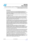
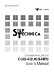
1
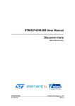
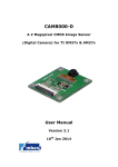
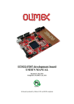
DM-CAM130 A CMOS image sensor which is a 1.3 Megapixel Digital Camera Supports STM32F2x and STM32F4x series micro controller Supports image preview, photos taking, and photo storage User Manual COPYRIGHT DM-CAM130 is trademarks of Embest Technology Co.,LTD. STM32F207, STM32 F407 are trademarks of STMicroelectronics Microsoft, MS-DOS, Windows XP are trademarks of Microsoft Corporation. Important Notice Embest has ownership and rights to the use of this document. Information in the document is within the protection of copyright. Unless specifically allowed, any part of this Document should not be modified, issued or copied in any manner or form without prior written approval of Embest Technology Co., LTD. Page 1 of 17 Version of update records: Rev Date Description V1.0 2012-8-23 Initial version Page 2 of 17 Contact: If you want to order products from Embest, please contact Marketing Department: Tel: +86-755-25635656 / 25636285 Fax: +86-755-25616057 E-mail: [email protected] If you want to get technical assistance from Embest, please contact Technical Assistance Department: Tel: +86-755-25503401 E-mail: [email protected] URL: http://www.armkits.com Address: Room 509, Luohu Science &Technology Building, #85 Taining Road, Shenzhen, Guangdong, China (518020) Page 3 of 17 Contents Charter 1 Overview...................................................................................................... 6 1.1 Product Introduction ............................................................................................. 6 1.2 Definition .............................................................................................................. 6 1.3 Feature ................................................................................................................ 6 Charter 2 Interface....................................................................................................... 7 2.1 FPC Interface CON2 ............................................................................................ 7 2.2 FPC Interface CON1 ............................................................................................ 8 2.3 Hardware Dimensions ........................................................................................ 10 Charter 3 Getting Started ........................................................................................... 11 3.1 How to work with DevKit1207 ............................................................................ 11 3.1.1 Preparation .............................................................................................. 11 3.1.2 Testing ..................................................................................................... 11 3.2 How to work with DevKit407 .............................................................................. 13 3.1.1 Preparation .............................................................................................. 13 3.1.2 Testing ..................................................................................................... 13 Technical support & Warranty Service ............................................................................ 15 Technical support service ......................................................................................... 15 Maintenance service clause ..................................................................................... 16 Basic notice to protect and maintenance LCD ......................................................... 17 Value Added Services .............................................................................................. 17 Page 4 of 17 Charter 1 Overview 1.1 Product Introduction DM-CAM130 Digital Camera Module designed by Embest, can be used on DevKit1207 DevKit407 evaluation board. This module contains an OV9655, which is a 1.3megapixel CMOS SXGA image sensor. This module supports image preview, photo taking and photo storage. It is suitable for applications such as Portable Digital Terminal, Gaming and Home Automation. 1.2 Definition SCCB: Serial Camera Control Bus (I2C like protocol). SXGA: Super eXtended Graphics Array (Resolution: 1280x1024). 1.3 Feature Table 1-1 Hardware feature Dimension 47.8mm*37.6mm*6mm Signal System CMOS 1.3 Mega Pixel Resolution Up to 1280*1024 15fps for SXGA Frame Rate 30fps for VGA,CIF Interface 30-pin FPC connector Power Supply From board Operating Temp. -10℃~70℃ Table 1-2 Software feature Photo Taking Support Photo Storage Support, BMP format Page 5 of 17 Charter 2 Interface CON2 CON1 Figure 2-1 Hardware interface 2.1 FPC Interface CON2 Table 2-1 OV9655 FPC Connector CON2 CON2 Pin Signal Description 1 Y0 Output bit[0] - LSB for 10-bit RAW RGB data only 2 Y1 Output bit[1] - for 10-bit RGB only 3 Y4 Output bit[4] 4 Y3 Output bit[3] 5 Y5 Output bit[5] 6 Y2 Output bit[2] - LSB for 8-bit YUV 7 Y6 Output bit[6] 8 PCLK Pixel clock output 9 Y7 Output bit[7] Page 6 of 17 10 DGND Digital ground 11 Y8 Output bit[8] 12 XCLK Crystal clock input 13 Y9 Output bit[9] - MSB for 10-bit RGB and 8-bit YUV 14 DOVDD28 Digital power supply (VDD-IO= 2.5 to 3.3 VDC) 15 DVDD18 Power supply (VDD-C= 1.8 VDC + 10%) for digital output drive 16 HREF HREF output 17 PWDN Power Down Mode Selection 0: Normal mode 1: Power down mode 18 VSYNC Vertical sync output 19 RESET Clears all registers and resets them to their default values. 0: Reset mode 1: Normal down mode 20 SIO_C SCCB serial interface clock input 21 AVDD Analog power supply (VDD-A= 2.45 to 2.8 VDC) 22 SIO_D SCCB serial interface data I/O 23 AGND Analog ground 24 NC No connect 2.2 FPC Interface CON1 Table 2-2 FPC Connector CON1 CON1 Pin Signal Description 1 GND GND 2 D0 No connect 3 D1 No connect Page 7 of 17 4 D2 Digital image data bit 0 5 D3 Digital image data bit 1 6 D4 Digital image data bit 2 7 D5 Digital image data bit 3 8 D6 Digital image data bit 4 9 D7 Digital image data bit 5 10 D8 Digital image data bit 6 11 D9 Digital image data bit 7 12 D10 No connect 13 D11 No connect 14 GND GND 15 PCLK Pixel clock 16 GND GND 17 HS Horizontal synchronization 18 VDD50 No connect 19 VS Vertical synchronization 20 VDD33 +3.3V 21 XCLKA Clock output 22 XCLKB No connect 23 GND GND 24 FLD No connect 25 PWR_EN Power Enable (Default=0) 26 RST Reset the camera (Default=1) 27 SDA I2C master serial clock 28 SCL I2C serial bidirectional data 29 GND GND 30 VDDIO +3.3V Page 8 of 17 2.3 Hardware Dimensions The hardware dimensions of DM-CAM130 (Units: mm): Figure 2-2 Hardware Dimensions Diagram Page 9 of 17 Charter 3 Getting Started 3.1 How to work with DevKit1207 3.1.1 Preparation Hardware: DevKit1207 Target Board DM-CAM130 Module 5V power adapter TF card (2GB or less than 2GB Kingston or SanDisk TF Card is recommended. It should be formatted before using) Software: DCMI demo The demo project is located in following folder: DCMI_OV9655\Project\STM32F2xx_StdPeriph_Examples\DCMI 3.1.2 Testing In order to run DCMI demo, please follow steps below: 1) Connect DM-CAM130 CON1 to DevKit1207 CON6 via FFC soft cable. Please make sure that DM-CAM130 module is mounted correctly as following Page 10 of 17 Figure 3-1 Connect DM-CAM130 to DevKit1207 via FFC soft cable 2) Insert TF card into DevKit1207 CON4, and make sure that JP5&JP6 are fitted; JP7&JP8 and JP10&JP11 are not fitted. 3) Plug in +5V power supply to the DevKit1207. 4) Rebuild the demo, and then download the program into Flash. 5) Press RESET button to reset MCU. It will start to run automatically. 6) Images collected by the module will be show on LCD. If LCD display “Camera Init … fails”, please make sure that DM-CAM130 module is mounted correctly and try again follow by step1) to step 5). 7) Press USER2 button 2 ~ 3 second to take a photograph. The photograph will be stored into TF card automatically and named as “PICxx.BMP”. ”xx” is picture’s number; “BMP” is picture’s format. Note: If one of the following situations appear, please check whether DM-CAM130 module is well-connected to DevKit1207 via FFC soft cable. Then try again following step 1) to step 5). LCD display “Camera Init …fails” LCD display all white Images collected by the module is color difference Page 11 of 17 3.2 How to work with DevKit407 3.1.1 Preparation Hardware: DevKit407 Target Board DM-CAM130 Module USB type A (Male) to Mini-B (Male) cable TF card (2GB or less than 2GB Kingston or SanDisk TF Card is recommended. It should be formatted before using) Software: DCMI demo The demo project is located in following folder: DCMI_OV9655\Project\STM32F2xx_StdPeriph_Examples\DCMI 3.1.2 Testing In order to run the example, please follow the steps below: Page 12 of 17 Figure 3-2 Steps for running DCMI example 1) Connect DM-CAM130 CON1 to DevKit407 CON7 via FFC soft cable when the power is turned off. Please make sure that DM-CAM130 module is mounted correctly. Note: Make sure that JP1 and JP2 are not fitted. 2) Insert a TF card into microSD slot CON6. 3) Connect DM-LCD35RT module onto DevKit407 board through CON3 4) Connect the STM32F4DISCOVERY board to a PC with a 'USB type A to Mini-B' cable through USB connector CN1 to power the board. 5) Open the MDK project, rebuild all files, load project image and then run program. 6) When the program is running, images collected by the module is shown on LCD. Press User button to take a photograph. The photograph will be stored into TF card automatically and named as “PICxx.BMP”. ”xx” is picture’s number; “BMP” is picture’s format. Note: If one of the following situations appear, please check whether DM-CAM130 module is well-connected to DevKit1207 via FFC soft cable. Then try again following step 1) to step 6). LCD display “Camera Init …fails” LCD display all white Images collected by the module is color difference Page 13 of 17 Technical support & Warranty Service Embest Technology Co.,LTD., established in March of 2000, is a global provider of embedded hardware and software. Embest aims to help customers to reduce time to market with improved quality by providing the most effective total solutions for the embedded industry. In the rapidly growing market of high end embedded systems, Embest provides comprehensive services to specify develop and produce products and help customers to implement innovative technology and product features. Progressing from prototyping to the final product within a short time frame and thus shorten the time to market, and to achieve the lowest production costs possible. Embest insists on a simple business model to offer customers high-performance, low-cost products with best quality and service. The content below is the matters need attention for our products technical support and warranty service: Technical support service Embest provides one year free technical support service for all products. Technical support service covers: Embest embedded platform products software/hardware materials Assist customers compile and run the source code we offer. Solve the problems occurs on embedded software/hardware platform if users follow the instructions in the documentation we offer. Judge whether the product failure exists. Special explanation, the situations listed below are not included in the range of our free technical support service, and Embest will handle the situation with discretion: Software/Hardware issues user meet during the self-develop process Issues happen when users compile/run the embedded OS which is tailored by users themselves. Page 14 of 17 User’s own applications. Problems happen during the modification of our software source code Maintenance service clause 1) The products except LCD, which are not used properly, will take the warranty since the day of the sale: PCB: Provide 12 months free maintenance service. 2) The situations listed below are not included in the range of our free maintenance service, Embest will charge the service fees with discretion: a) Can’t provide valid Proof-of-Purchase, the identification label is torn up or illegible, the identification label is altered or doesn’t accord with the actual products; b) Don’t follow the instruction of the manual in order to damage the product; c) Due to the natural disasters ( unexpected matters ), or natural attrition of the components, or unexpected matters leads to the defects of appearance/function; d) Due to the power supply, bump, leaking of the roof, pets, moist, impurities into the boards, all those reasons which lead the defects of appearance/function; e) User unauthorized weld or dismantle parts leads the product’s bad condition, or let other people or institution which are not authorized by Embest to dismantle, repair, change the product leads the product bad connection or defects of appearance/function; f) User unauthorized install the software, system or incorrect configuration or computer virus leads the defects; g) Purchase the products through unauthorized channel; h) Those commitments which is committed by other institutions should be responsible by the institutions, Embest has nothing to do with that; Page 15 of 17 3) During the warranty period, the delivery fee which delivery to Embest should be covered by user, Embest will pay for the return delivery fee to users when the product is repaired. If the warranty period is expired, all the delivery fees will be charged by users. 4) When the board needs repair, please contact technical support department. Note: Those products are returned without the permission of our technician, we will not take any responsibility for them. Basic notice to protect and maintenance LCD 1) Do not use finger nails or hard sharp object to touch the surface of the LCD, otherwise user can’t enjoy the above service. 2) Embest recommend user to purchase a piece of special wiper to wipe the LCD after long time use, please avoid clean the surface with fingers or hands to leave fingerprint. 3) Do not clean the surface of the screen with chemicals, otherwise user can not enjoy above service. Note: Embest do not supply maintenance service to LCD. We suggest the customer first check the LCD after getting the goods. In case the LCD can not run or show no display, customer should inform Embest within 7 business days from the moment of getting the goods. Value Added Services We will provide following value added services: Page 16 of 17 Provided services of driver develop based on Embest embedded platform, like serial port, USB interface devices, LCD screen. Provided the services of control system transplant, BSP drivers development, API software development. Other value added services like power adapter, LCD parts. Other OEM/ODM services. Technically training. Please contact Embest to get technical support: Support Tel:+86-755-25503401 Fax:+86-755-25616057 Pre-Sale consultation: [email protected] After-Sale consultation: [email protected] Page 17 of 17