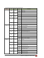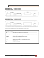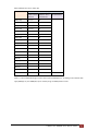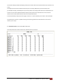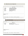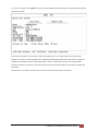
1
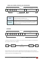
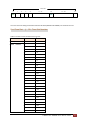
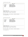
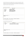
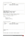
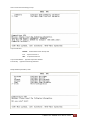
Proscend
NTU-5066GM
Series
User Manual
Version 0.02
Tables of Contents
1
INTRODUCTION ........................................................................................................................................ 3
1.1
2
1.1.1
E1 interface model .......................................................................................................................... 3
1.1.2
Serial interface model...................................................................................................................... 3
1.1.3
Ethernet interface model................................................................................................................. 3
1.1.4
Co-directional interface model ........................................................................................................ 3
1.2
FEATURES ................................................................................................................................................... 4
1.3
SPECIFICATION ............................................................................................................................................. 4
GETTING TO KNOW ABOUT THE SHDSL NTU ............................................................................................. 7
2.1
3
MODELS ..................................................................................................................................................... 3
FRONT PANEL .............................................................................................................................................. 7
2.1.1
E1 interface model .......................................................................................................................... 7
2.1.2
Serial interface model...................................................................................................................... 7
2.1.3
Ethernet interface model................................................................................................................. 8
2.1.4
Co-directional interface model ........................................................................................................ 8
2.2
DATA RATE DISPLAY BY LEDS ........................................................................................................................ 12
2.3
REAR PANEL .............................................................................................................................................. 13
2.3.1
E1 Interface Model ........................................................................................................................ 13
2.3.2
Serial Interface Model ................................................................................................................... 14
2.3.3
Ethernet Interface Model .............................................................................................................. 15
2.3.4
Co-directional Interface Model...................................................................................................... 16
2.4
INSTALLATION............................................................................................................................................ 17
2.5
CAUTION ............................................................................................................................................... 18
CONFIGURATION WITH CONSOLE PORT ................................................................................................. 20
3.1
LOGIN PROCEDURE ..................................................................................................................................... 20
3.2
WINDOW STRUCTURE ................................................................................................................................. 21
3.3
MENU COMMANDS .................................................................................................................................... 22
3.4
MAIN MENU SUMMARY.............................................................................................................................. 23
3.5
[SETUP] CONFIGURATION ............................................................................................................................ 24
3.5.1
Configure Interface ........................................................................................................................ 27
3.5.2
Configure SHDSL parameters ........................................................................................................ 28
3.5.3
Configure E1 parameters............................................................................................................... 34
3.5.4
Configure Serial parameters .......................................................................................................... 44
3.5.5
Configure Ethernet parameters ..................................................................................................... 51
3.5.6
Configure Co-directional parameters ............................................................................................ 55
3.5.7
Enable and Disable Remote configuration .................................................................................... 56
3.5.8
Restore factory default setting ...................................................................................................... 57
3.5.9
DIP Switch function ....................................................................................................................... 59
G.SHDSL NTU 5066GM User Manual V0.02
1
3.6
[NETWORK] SETUP THE NETWORK PARAMETER ................................................................................................ 61
3.7
[STATUS] VIEW THE SYSTEM STATUS .............................................................................................................. 68
3.7.1
Show SHDSL Status ........................................................................................................................ 69
3.7.2
Show Interface Status.................................................................................................................... 71
3.7.3
Show Current Performance ........................................................................................................... 74
3.7.4
View the Local and remote Statistics ............................................................................................ 76
3.7.5
Clear Channel Statistics ................................................................................................................. 80
3.8
4
[SHOW] VIEW SYSTEM CONFIGURATION......................................................................................................... 81
3.8.1
Show General Interface ................................................................................................................. 81
3.8.2
Show configuration in listing format ............................................................................................. 83
3.8.3
Show configuration in command script ......................................................................................... 85
3.9
[REBOOT] REBOOT THE SYSTEM .................................................................................................................... 88
3.10
[DIAG] DIAGNOSTIC – LOOPBACK AND BER TEST ............................................................................................. 90
3.10.1
Loopback test ................................................................................................................................ 90
3.10.2
BER Test ......................................................................................................................................... 93
3.10.3
Loopback setup and BER test by push button switch .................................................................... 94
3.11
[UPGRADE] FIRMWARE UPGRADE .................................................................................................................. 95
3.12
[EXIT] EXIT THE SYSTEM ............................................................................................................................. 100
APPENDIX ............................................................................................................................................. 101
4.1
ABBREVIATION......................................................................................................................................... 101
4.2
SERIAL INTERFACE PIN ASSIGNMENTS........................................................................................................... 104
4.3
V.35 DB25(M) TO M.34(F) ADAPTOR CABLE .............................................................................................. 106
4.4
X.21 DB25(M) TO DB15(F) ADAPTOR CABLE .............................................................................................. 108
4.5
CONSOLE CABLE....................................................................................................................................... 110
4.6
E1 BALANCE CABLE .................................................................................................................................. 112
4.7
CO-DIRECTIONAL BALANCE CABLE ............................................................................................................... 113
4.8
E1 UNBALANCE CABLE .............................................................................................................................. 114
4.9
ETHERNET CABLE ..................................................................................................................................... 115
4.10
DSL CABLE ............................................................................................................................................. 116
4.11
POWER CORD .......................................................................................................................................... 117
4.12
ILLUSTRATION OF LOOPBACK CONNECTION DEVICE (E1) ................................................................................... 118
4.13
ILLUSTRATION OF LOOPBACK CONNECTION DEVICE (SERIAL) .............................................................................. 119
G.SHDSL NTU 5066GM User Manual V0.02
2
1 Introduction
1.1 Models
The G.SHDSL NTU 5066GM series offers four different interface models: E1 interface, Serial interface, Ethernet
interface and Co-direction interface. They can connect customers to high-speed TDM services .This series have
eight models on the following:-
1.1.1 E1 interface model
Products Number:
5066GM-DA/2W/E1
5066GM-DA/2W/E1/LCD
It offers two different ways have connected customers to high-speed TDM services with two G.703 E1
interfaces (Balance 120Ω RJ45 jack and Unbalance 75Ω dual BNCs). The G.703 interface can carry 64kbps to
2.048Mbps.
1.1.2 Serial interface model
Products Number:
5066GM-DA/2W/SER
5066GM-DA/2W/SER/LCD
It offers customers premises has high-speed and low-speed TDM services with a DB25 interface. The industry
standard DB25 interface can be configured as a V.35/RS530 or V.36/X.21 connection. The DB25 connection can
transfers data up to 2.304Mbps.
1.1.3 Ethernet interface model
Products Number:
5066GM-DA/2W/ETH
5066GM-DA/2W/ETH/LCD
It offers customers premises has high-speed TDM services with four LAN interface. The industry standard LAN
interface can detect a 10Mbps or 100Mbps connection automatically.
1.1.4 Co-directional interface model
Products Number:
5066GM-DA/2W/COD
5066GM-DA/2W/COD/LCD
G.SHDSL NTU 5066GM User Manual V0.02
3
It offers customers premise has low-speed TDM services with balance 120Ω RJ-45 interface. The industry
standard Co-directional interface can transfer 64Kbps.
They can be configured and managed via EOC, or menu-driven VT100 compatible Asynchronous Terminal
Interface, either locally or remotely. Also, they can be configured and manage by management port with
SNMP.
The G.SHDSL NTU 5066GM series is equipped with an auto rate capability that identifies the maximum line rate
supported by the copper loop. This powerful automatic configuration capability makes installation and service
provisioning simple and painless. Further flexibility is provided in the ability to manually set the maximum NTU
speed at different levels for different customer-tailored service offerings.
1.2 Features
Standard G.SHDSL (ITU G.991.2) supports improved reach/speed and greater interoperability
Fast and cost-effective provisioning of traditional frame relay (FR or T-HDLC) or TDM leased line services
User existing copper loop infrastructures
Can operate back to back connection
Efficient single wire pair usage
Up to 2.312Mbps symmetric service bit rate
Auto rate installation maximizes data rate based on loop conditions
Wetting current sink to protect SHDSL line
Remote line loopback
SHDSL Line performance monitoring (Data Rate and SNR)
Raw and per time interval statistics
Bandwidth guaranteed transmission equipment
SNMP management port with SNMP version 1 and 2C
Remote firmware upgrade
Can use AC or DC power input
1.3 Specification
WAN Interface
•
Line Rate: SHDSL per G.991.2
•
Coding: trellis coded pulse amplitude modulation (TCPAM-16)
•
Support: Annex A(ANSI) and Annex B(ETSI)
•
Payload rates:
64kbps to 2.304Mbps (N x 64kbps N=1 to 36) for Serial and Ethernet interface
64kbps to 2.048Mbps (N x 64kbps N=1 to 32) for E1 interface
64kbps (N x 64kbps N=1 ) for Co-direction interface
G.SHDSL NTU 5066GM User Manual V0.02
4
•
Connection: RJ-45 jack
•
Impedance: 135 ohms
E1 Interface
•
Connection:
RJ-45 for balanced 120Ω E1 cable
•
Connection:
BNC for unbalanced 75Ω E1 cable
•
Line Rate:
•
Framing:
•
Data Rate:
64Kbps to 2.048Mbps (Nx64Kbps , N=1 to 32)
•
Operation:
Full E1 and Fractional E1
2048KHz +/- 50ppm
PCM30 / PCM30C / PCM31 / PCM31C and Unframed
SERIAL Interface (as V.35)
•
Connection:
DB-25(F)
•
Connection:
M.34
•
Payload rates:
•
Support RS-530, V.35 or V.36/X.21
Up to 2.304Mbps (N=1 to 36)
LAN Interface (as Ethernet)
•
Single Ethernet Interface
•
10/100Mpbs Half/Full Duplex, Auto-sensing, Auto-Crossover
•
Up to 2048 MAC address learning
•
Connection: RJ-45 for Ethernet cable
Co-directional Interface
:
•
Interface Rate Co directional G.703 interface 64kbps +-50PPM
•
Interface coding ITU-T G.703
•
•
:
:120Ω (balance)
Interface character:match G.703
Impedance
•
Connection:
•
Payload rates:
RJ-45 for balanced 120Ω cable
64Kbps
DSL Timing
•
Internal
•
From E1 Recovery (as E1)
•
From DTE (as V.35, Ethernet and Co-direction)
Performance Monitoring
•
ES, SES, UAS, LOSW, Alarms, Errors
Loopback Tests
•
Digital Local Loopback
G.SHDSL NTU 5066GM User Manual V0.02
5
•
Digital Loopback
•
Remote Line Loopback
•
Remote Payload Loopback
•
Far-end Line Loopback
•
Far-end Payload Loopback
•
V.54(For V.35 interface model only)
•
Build-in 511 bit (2 -1) BER tester
9
Management
•
Console port (RJ45)
•
Management Port ( RJ-45)
•
Support firmware upgradeable
Physical/Electrical
•
Dimensions: 216mm x 154mm x 42mm
•
Input:
For AC power input version 100 to240Vac with 50 to 60Hz
For DC Power input version -36 to72Vdc
•
Power Consumption: 12W Max
•
Operation temperature: 0 to 40°C
•
Humidity: Up to 95% (non-condensing)
•
External screw for frame grounding
Order information:
Without LCD display
With LCD display
E1 Interface
Type A:
2 x BNC and 1 x RJ-45
Type B:
1 x RJ-45
5066GM-DA/2W/E1
5066GM-DA/2W/E1/LCD
5066GM-DA/2W/SER
5066GM-DA/2W/SER/LCD
5066GM-DA/2W/ETH
5066GM-DA/2W/ETH/LCD
5066GM-DA/2W/COD
5066GM-DA/2W/COD/LCD
Serial Interface
Type A:
1 x DB-25
Type B:
1 x M.34
Ethernet Interface
4 x RJ-45
Co-Directional Interface
1 x RJ-45
G.SHDSL NTU 5066GM User Manual V0.02
6
2 Getting to know about the SHDSL NTU
This chapter shows the front and rear panel and how to install the hardware.
2.1 Front Panel
2.1.1 E1 interface model
5066GM-DA/2W/E1
5066GM-DA/2W/E1/LCD
2.1.2 Serial interface model
5066GM-DA/2W/SER
5066GM-DA/2W/SER/LCD
G.SHDSL NTU 5066GM User Manual V0.02
7
2.1.3 Ethernet interface model
5066GM-DA/2W/ETH
5066GM-DA/2W/ETH/LCD
2.1.4 Co-directional interface model
5066GM-DA/2W/COD
5066GM-DA/2W/COD/LCD
G.SHDSL NTU 5066GM User Manual V0.02
8
The following table describes the function of push button switch:
5066GM-DA/2W/E1
5066GM-DA/2W/SER
5066GM-DA/2W/ETH
5066GM-DA/2W/COD
LLP
Local Loopback
RLP
Remote payload Loopback
BERT
SP
BER Test
Set date rate
5066GM-DA/2W/E1/LCD
5066GM-DA/2W/SER/LCD
5066GM-DA/2W/ETH/LCD
5066GM-DA/2W/COD/LCD
Left
Right
EXIT
ENTER
Exit
Enter
G.SHDSL NTU 5066GM User Manual V0.02
9
The following table describes the function of LED indicators:
Usage
LED
Color
PWR
Green
Common use
TEST
BERT
DSL
Action
On
Power is on.`
Off
Power is off.
On
Loopback test is on
Off
Loopback test is off
On
BER test is on
Off
BER Test is off
On
SHDSL line is connected.
Yellow
Green
Green
Blink
Off
Blink
ERR
BPV
R/AIS
FULL
ALM
CTS
TXD
RXD
ALM
SHDSL line is dropped.
Error second occurs.
Off
No error second.
On
E1 line is connected.
Off
E1 line is dropped.
On
Bipolar Violation error
Off
No Bipolar Violation error
On
Alarm Indication Signal is on
Off
Alarm Indication Signal is off
On
Unframed mode
Off
Framed mode
On
SHDSL or E1 link is connect
Off
SHDSL or E1 link is dropped
On
RTS is on
Off
RTS is off
On
CTS is on
Off
CTS is off
On
Data transmit in V.35.
Off
No data transmit in V.35.
On
Data receive in V.35.
Off
No data reveive in V.35.
On
SHDSL link is connect
Off
SHDSL link is dropped
Green
Green
Green
Green
Red
Serial
RTS
Data transmit in SHDSL line.
Red
E1
SYNC
Description
Green
Green
Green
Green
Red
G.SHDSL NTU 5066GM User Manual V0.02
10
Ethernet
LAN1
On
LAN2
Green
Blink
Ethernet line is connected.
Data transmit in Ethernet line.
LAN3
LAN4
ALM
BPV
TXD
RXD
ALM
Ethernet line is dropped.
On
SHDSL link is connect
Off
SHDSL link is dropped
On
Co-directional line is connected.
Off
Co-directional line is dropped.
On
Bipolar Violation error
Off
No Bipolar Violation error
On
Data transmit in Co-directional
Off
No data transmit in Co-directional
On
Data receive in Co-directional
Off
No data reveive in Co-directional
On
SHDSL link or Co-directional link is connect
Off
SHDSL link or Co-directional link is dropped
Red
Co-directional
SYNC
Off
Green
Green
Green
Green
Red
G.SHDSL NTU 5066GM User Manual V0.02
11
2.2 Data rate display by LEDs
This function will using on without LCD display models:
5099GM-DA/2W/E1
5099GM-DA/2W/SER
5099GM-DA/2W/ETH
5099GM-DA/2W/COD
○ ○ ○ ○ ● ● ● ● ● ●
10
9
8
7
6
LED-5
5
3
1
LED-6
N
5
2
2
2
2
2
2
36
ON
OFF
OFF
ON
OFF
OFF
35
ON
OFF
OFF
OFF
ON
ON
34
ON
OFF
OFF
OFF
ON
OFF
33
ON
OFF
OFF
OFF
OFF
ON
32
ON
OFF
OFF
OFF
OFF
OFF
31
OFF
ON
ON
ON
ON
ON
30
OFF
ON
ON
ON
ON
OFF
.
.
.
.
.
.
.
.
.
.
.
.
.
.
6
OFF
OFF
OFF
ON
ON
OFF
5
OFF
OFF
OFF
ON
OFF
ON
4
OFF
OFF
OFF
ON
OFF
OFF
3
OFF
OFF
OFF
OFF
ON
ON
2
OFF
OFF
OFF
OFF
ON
OFF
1
OFF
OFF
OFF
OFF
OFF
ON
3
LED-3
2
Rate
4
LED-4
4
2
LED-2
1
LED-1
0
G.SHDSL NTU 5066GM User Manual V0.02
12
2.3 Rear Panel
2.3.1 E1 Interface Model
5066GM-DA/2W/E1
(with BNC and RJ-48C)
5066GM-DA/2W/E1/LCD
(with BNC and RJ-48C)
5066GM-DA/2W/E1
(with RJ-48C)
5066GM-DA/2W/E1/LCD
(with RJ-48C)
The rear panel of this model is including DC power socket, power switch, AC power socket, RJ-45 console, RJ-45
management port, G.703 RJ-45 jack or BNC jack for transmitting and receiving and RJ-45 for DSL from left to
right.
Connector Description
ON
Power switch. Press 1 for turn on and press 0 for off
100~240V AC
IEC-320 C6 AC input connector. It has power adapting function from 100V to 240V
-48V
DC power input connector (-48V)
G
CONSOLE
RJ-45 for system configuration and maintenance
MGMT
RJ-45 for SNMP Management
G.703
RJ-48C for 120Ω E1 connection with PABX (Private Automatic Branch Exchange) or E1 Router
TX
BNC for 75Ω E1 transmitting
RX
BNC for 75Ω E1 receiving
DSL
RJ-45 for DSL connection
G.SHDSL NTU 5066GM User Manual V0.02
13
2.3.2 Serial Interface Model
5066GM-DA/2W/SER
( with DB-25 connecter)
5066GM-DA/2W/SER/LCD
( with DB-25 connecter)
5066GM-DA/2W/SER
( with M.34 connecter)
5066GM-DA/2W/SER/LCD
( with M.34 connecter)
The rear panel of this model is including DC power socket, power switch, AC power socket, RJ-45 console, RJ-45
management port, DB-25(Female) for serial and RJ-45 for DSL from left to right.
Connector Description
ON
Power switch. Press 1 for turn on and press 0 for off
100~240V AC
IEC-320 C6 AC input connector. It has power adapting function from 100V to 240V
-48V
DC power input connector (-48V)
G
CONSOLE
RJ-45 for system configuration and maintenance
MGMT
RJ-45 for SNMP Management
DB-25(F) for RS-530 and V.35 or X.21(with adaptor cable)
SERIAL
M.34(F) for V.35
DSL
RJ-45 for DSL connection
G.SHDSL NTU 5066GM User Manual V0.02
14
2.3.3 Ethernet Interface Model
5066GM-DA/2W/ETH
5066GM-DA/2W/ETH/LCD
The rear panel of this model is including DC power socket, power switch, AC power socket, RJ-45 console, RJ-45
management/LAN port and RJ-45 for DSL from left to right.
Connector Description
ON
Power switch. Press 1 for turn on and press 0 for off
100~240V AC
IEC-320 C6 AC input connector. It has power adapting function from 100V to 240V
-48V
DC power input connector (-48V)
G
CONSOLE
RJ-45 for system configuration and maintenance
MGMT
RJ-45 for SNMP Management
LAN
RJ-45 for LAN(1,2,3 and 4)
DSL
RJ-45 for DSL connection
G.SHDSL NTU 5066GM User Manual V0.02
15
2.3.4 Co-directional Interface Model
5066GM-DA/2W/COD
5066GM-DA/2W/COD/LCD
The rear panel of this model is including DC power socket, power switch, AC power socket, RJ-45 console, RJ-45
management port, G.703 RJ-45 jack for Co-Directional and RJ-45 for DSL from left to right.
Connector Description
ON
Power switch. Press 1 for turn on and press 0 for off
100~240V AC
IEC-320 C6 AC input connector. It has power adapting function from 100V to 240V
-48V
DC power input connector (-48V)
GND
CONSOLE
RJ-45 for system configuration and maintenance
MGMT
RJ-45 for SNMP Management
COD
RJ-45 for Co-Directional interface
DSL
RJ-45 for DSL connection
G.SHDSL NTU 5066GM User Manual V0.02
16
2.4 Installation
Note: To avoid possible damage to this router, do not turn on the product before hardware installation.
Plug the AC or DC power cord in the power socket.
Plug the console cable if you want to configure the NTU with VT100 program of NB or PC.
Plug the
E1 cable (Either 75Ω BNC cables or 120Ω cable)
Co-directional cable (120Ω cable)
SERIAL cable (V.35 cable)
Ethernet cable
Plug DSL cable
Power on
Protective earth:
The screw terminal above of DSL interface should be connected to the building protective earth bus.
The function of protective earth does not serve the purpose of providing protection against electrical shock,
but instead enhances surge suppression on the DSL lines for installations where suitable bonding facilities exist.
The connector type is M3 machine screw.
Wetting Current:
Wetting current, also known as loop sealing current, is a low-level DC current applied to a loop for the specific
purpose of maintaining cable splice integrity by preventing the build-up of oxidation. There has the ability to
sink the source wetting current.
G.SHDSL NTU 5066GM User Manual V0.02
17
2.5 CAUTION
CAUTION for accessibility
Be sure that the power outlet you plug the power card into is easily accessible and located as close as to the
equipment operator as possible. When you need to disconnect power to the equipment, be sure to unplug the
power card from the electrical outlet.
Warnings
Do not use this product near water.
Do not place this product on an unstable cart, stand or table. If the product falls, it could be seriously
damaged.
Slots and openings are provided for ventilation to ensure reliable operation of the product and to protect
it from overheating. These openings must not be blocked or covered. The openings should never be
blocked by placing the product on a bed, soft, rug or other similar surface. This product should never be
placed near or over a radiator or heat register, or in a built-in installation unless proper ventilation is
provided.
Never push objects of any kind into this product through cabinet slots as they may touch dangerous
voltage points or short-out parts that could result in a fire or electric shock. Never spill liquid of any kind
onto or into the product.
Using electrical power
This product should be operated from the type of power indicated on the marking label. If you are not
sure of the type of power available, consult your dealer or local power company.
Do not allow anything to rest on the power card. Do not locate this product where people will walk on
the cord.
If an extension cord is used with this product, make sure that the total ampere rating of the equipment
plugged into the extension cord does not exceed the extension card ampere rating. Also, make sure that
the total rating of all products plugged into the wall outlet does not exceed the fuse rating.
Do not overload a power outlet, strip or receptacle by plugging in too many devices. The overall system
load must not exceed 80% of the branch circuit rating. If power strips are used, the load should not
exceed 80% of the power strip’s input rating.
The product’s power supply is equipped with a three-wire grounding plug. The plug only fits in a
grounded power outlet. Make sure the power outlet is properly grounded before inserting the power
supply plug. Do not insert the plug into a non-grounded power outlet. Contact your electrician for details.
Warning! The grounding pin is a safety feature. Using a power outlet that is not properly grounded may result
in electric shock and/or injury.
G.SHDSL NTU 5066GM User Manual V0.02
18
Note: The grounding pin also provides good protection from unexpected noise produced by other nearby
electrical devices that may interfere with the performance of this product.
Product servicing
Do not attempt to service this product yourself, as opening or removing covers may expose you to dangerous
voltage points or other risks, Refer all servicing to qualified service personnel.
Unplug this product from the wall outlet and refer servicing to qualified service personnel when:
The power card or plug is damaged, cut or frayed
Liquid was spilled into the product
The product was exposed to rain or water
The product has been dropped or the case has been damaged
The product exhibits a distinct change in performance, indicating a need for service
The product does not operate normally after following the operating instructions
Note: Adjust only those controls that are covered by the operating instructions, since improper adjustment of
other controls may result in damage and will often require extensive work by a qualified technician to restore
the product to normal condition.
Disposal instructions
Do not throw this electronic device into the trash when discarding.
To minimize pollution and ensure utmost protection of the global environment, please recycle.
G.SHDSL NTU 5066GM User Manual V0.02
19
3 Configuration with Console Port
This chapter will deal with the specifics of configuration and operation of this product via console port with
terminal emulation program. The configuration G.SHDSL NTU is performed via a menu-driven embedded
software, using a standard ASCII terminal or a PC running a terminal emulation application connected to the
rear panel CONSOLE port.
Windows includes a terminal emulation program called HyperTerminal. Connect the appropriate
communication port from the PC to this device. After the physical connection is made, you are ready to
configure this product. Make sure you have connected the supplied RS-232C serial cable (DB9F to RJ-45 Plug) to
the console port on the rear panel on this product.
Run the terminal emulation program such as Hyper Terminal with the following setting:
Emulation:
VT-100 compatible
Band rate:
115200, Data bits: 8, Parity: None, Stop Bits: 1 , Flow Control: None
3.1 Login Procedure
At the start up screen, the login screen appears and you can login to this device. When the system prompts you
for a user and password, type “admin” both to enter is O.K.
G.SHDSL NTU 5066GM User Manual V0.02
20
3.2 Window structure
After you type the password, it will display the main menu.
Above screen capture shows the common structure for all windows used throughout the configuration console
terminal.
From top to bottom, the window is divided into four major sections.
The very top line displays the product name “SHDSL
NTU”.
Next a block of commands is listed where the ">>" symbol indicates the current cursor placeholder.
The next block down is the "command" section. The command that is selected and ready for execution is
displayed after the "Command:" prompt. The "<more…> designation indicates that there are other sub menus
to this command. The "Message:" field is used to display any special system messages or warnings.
Finally, at the very bottom of the screen is a help command line and reminder of the currently available
command keys. In most cases, the keyboards four cursor keys can be used to navigate all the menu system. If
for some reason your keyboard's cursor keys are not supported in the terminal emulation software, you may
uses the keys listed on the help command line.
G.SHDSL NTU 5066GM User Manual V0.02
21
3.3 Menu Commands
Before changing the configuration, familiarize yourself with the operations list in the following table. The
operation list will be shown on the window.
Keypads
Description
[UP] or I
Move to above field in the same level menu
[DOWN] or K
Move to below field in the same lever menu
U
Move to top field in the same level menu
O
Move to bottom field in the same level menu
[LEFT] or J
Move back to previous menu (Exit)
[RIGHT] , L or [ENTER]
Move forward to submenu(Enter)
[TAB]
To choose another parameters
Ctrl + C
To quit the show data display screen
G.SHDSL NTU 5066GM User Manual V0.02
22
3.4 Main Menu Summary
The main menu is prompt as follow.
Menu Title
Function
Setup
To setup SHDSL type, SHDSL parameters and E1/Serial/Ethernet/Co-directional
parameters or restore factory default setting.
Network
To setup hostname, IP, net mask, gateway and SNMP.
Status
To show SHDSL status, E1 /V.35/Ethernet/Co-directional status and statistics or clear
the statistics on both local and remote side.
Show
To show general information, all configurations and all configurations in command
script format.
Reboot
To reboot the system
Diag
To setup diagnostic utility
Upgrade
To upgrade firmware (kernel and FPGA code)
Exit
To exit this system
G.SHDSL NTU 5066GM User Manual V0.02
23
3.5 [Setup] Configuration
This section provides information about configuration the G.SHDSL NTU. Follow the procedures:
In main menu, select setup and press [ENTER] or [RIGHT]
Press [ENTER] or [L] key to select which channel (Local side or Remote side).
G.SHDSL NTU 5066GM User Manual V0.02
24
The screen will prompt as following:
For E1 interface model
5066GM-DA/2W/E1
5066GM-DA/2W/E1/LCD
You can see E1 parameter can been setting.
For Serial interface model
5066GM-DA/2W/SER
5066GM-DA/2W/SER/LCD
You can see Serial parameter can been setting.
G.SHDSL NTU 5066GM User Manual V0.02
25
For Ethernet interface model
5066GM-DA/2W/ETH
5066GM-DA/2W/ETH/LCD
You can see Ethernet parameter can been setting.
For Co-directional interface model
5066GM-DA/2W/COD
5066GM-DA/2W/COD/LCD
You can see Co-directional parameter can been setting.
G.SHDSL NTU 5066GM User Manual V0.02
26
3.5.1 Configure Interface
Select Interface item, and press [ENTER] or [RIGHT] to setup NTU Interface.
The interface item display is according to what is the model, you can’t change this configuration items.
For example, if the model is 5099GM-DA/2W/E1 , then the SHDSL interface is E1. This item can’t change.
G.SHDSL NTU 5066GM User Manual V0.02
27
3.5.2 Configure SHDSL parameters
This section will introduce the configuring of SHDSL parameters.
Select Shdsl , and press [ENTER] or [RIGHT].
The SHDSL parameters items have SHDSL Mode, Annex type, PSD, SNR margin, Power Backoff and Backward.
For configuring SHDSL mode, move the cursor to Mode and press [ENTER] or [L]. Select the SHDSL mode by
using [TAB] key.
G.SHDSL NTU 5066GM User Manual V0.02
28
Setup SHDSL parameter, Mode
There are three SHDSL modes can be used: STU-R, STU-C-INTCLK and STU-C-EXTCLK.
INTCLK: The device will generate the appropriate clock speed defined by the speed setting of the interface.
EXTCLK: The device will accept the clock from the interface and will use that clock to receive and transmit data
across the interface.
Most applications use Internal Clock. If the DTE provides a clock with TX data, the clock can set to be External
Clock.
The following are commonly used acronyms for SHDSL MODE:
STU-R
RT side, where the clock source is set to external
STU-C-INTCLK
CO side, where the clock source is set to internal
STU-C-EXTCLK
CO side, where the clock source is set to external
For configuring SHDSL Annex type, move the cursor to Annex and press [ENTER or [L]]. Select the Annex type
by using [TAB] key.
G.SHDSL NTU 5066GM User Manual V0.02
29
Setup SHDSL parameter, Annex
There are two annex type can be used:
Annex-A and Annex-B
G.SHDSL NTU 5066GM User Manual V0.02
30
For configuring SHDSL PSD, move the cursor to psd and press [ENTER] or [L]. Select the parameter by using
[TAB] key.
Setup SHDSL parameter, PSD
There are four PSD type can be used: R1_ASM, R2_ASM, SYM_ENABLE and ASYM_DISABLE.
For setting SHDSL Margin, move the cursor to margin and press [ENTER] or [L]. You can key the SHDSL margin
setting value.
Setup SHDSL parameter, SNR Margin
G.SHDSL NTU 5066GM User Manual V0.02
31
SNR margin is an index of line connection. You can see the actual SNR margin from 0 to 10 in STATUS SHDSL.
The larger SNR margin has the better line connection. For example, if you set SNR margin in the field as 3, the
SHDSL connection will drop down and reconnect when the SNR margin is lower than 3.
For configuring SHDSL Power Back off function, move the cursor to Pwr Backoff and press [ENTER] or [L]. Select
the parameter by using [TAB] key.
Setup SHDSL parameter, Power Backoff
There are two power back-off type can be used: Disable and Enable.
When DSL line is used with short
distance, user may set Enable, it can use lower transmit power to get better signal to noise ratio.
Setup SHDSL parameter, Backward
G.SHDSL NTU 5066GM User Manual V0.02
32
When this NTU connect to other NTU with old models, it may have some compatibility problem. You can set
the item to ON for get better compatibility.
Setting Table on SHDSL parameter:
SETUP SHDSL
Selection items
MODE
STU-R,
STU-C-INTCLK,
ANNEX
A,
STARTUP MARGIN
DISABLE , 0
PSD
R1_ASTM,
POWER BACK OFF
Disable,
BACKWARD
On, Off
STU-C-EXTCLK
B
to
10
R2_ASYM,
SYM_ENABLE,
ASYM_DISBALE
Enable
G.SHDSL NTU 5066GM User Manual V0.02
33
3.5.3 Configure E1 parameters
When using on E1 interface, select the E1 item and press [ENTER] or [RIGHT].
The E1 settings include Channel, line code, AIS and build out settings.
Setup E1 Parameter, Channel
G.SHDSL NTU 5066GM User Manual V0.02
34
Framing is required to recover the channelized E1. In transparent operation, the framing is configured as
Unframed. In this case the G.SHDSL framer must be set to Nx64 with N=32. For any framing such as FAS or CAS,
the G.SHDSL framer must be set to E1, then the E1 framing here may be set accordingly. The default setting is
PCM31C.
E1 Framer Setting:
Framer
Slot Number
First Slot
PCM31
FAS
1 to 31
1 to 31
PCM31C
FAS+CRC4
1 to 31
1 to 31
PCM30
FAS+CAS
1 to 30
1 to 31 (can’t use 16)
PCM30C
FAS+CAS+CRC4
1 to 30
1 to 31 (can’t use 16)
FULL
UNFRAMED
Information of FAS:
Frame Alignment Signal use 7-bit pattern to establish and maintain frame
FAS
synchronization. The FAS word is located in timeslot 0 of frame. In FAS mode there
have 1~31 timeslot available for use data.
PCM31
and
PCM31C ( FAS
and
FAS+CRC4)
Time Slot
0
1
2
3
4
5
6
7
8
9 ~ 30
31
64k
64k
64k
64k
64k
64k
64k
64k
1408k
64k
FAS
64k
Maximun Data Rate 1948kbps
Information of CAS:
Also known as time slot 16 multiframing. It requires a multiframe alignment
signal to be present for frame sync. The Multiframe Alignment Signal (MFAS) is
CAS
inserted into the 16th timeslot of frame 0 of the 16-frame multiframe.
In CAS mode, there have 30 channels available for user data. If timeslot 16 is
included in the unit’s mapping, it will be disregarded.
G.SHDSL NTU 5066GM User Manual V0.02
35
PCM30
and
PCM30C (FAS+CAS
and
FAS+CAS+CRC4)
Time Slot
0
1
2
3
4
16
5 ~ 15
FAS
64k
17 ~ 30
31
896k
64k
CAS
64k
64k
64k
704k
64k
64k
Data Rate (x) 960kbps
Data Rate (y) 960kbps
Maximun Data Rate = x + y = 1920kbps
The CRC-4 checksum bits are transmitted in the outgoing E1 data stream.
CRC4
Also the received signal is checked for errors.
CRC-4 checksum cannot be sent in unframed mode.
In this mode, user data is inserted into all 32 channels (64k x 32 = 2048k) of
Unframed
the E1 stream. The object of running without framing is to utilize the full
bandwidth of the E1 line.
UNFRAMED
Time Slot
0
1
2
3
4
5
6
7
8
9 ~ 30
31
64k
64k
64k
64k
64k
64k
64k
64k
64k
1408k
64k
Maximun Data Rate 2048kbps
G.703 (E1) can supports data rate of 2048kbps, so the maximum data rate of SHDSL line, connected with E1
DCEs, depends on data rate of E1, 2048kbps.
E1
DTE
SHDSL
STU-R (E1)
STU-C (E1)
E1
DTE
Frame E1
Data rate 2048
If the connection is E1 vs V.35 or V.35 vs E1, the frame has to be used N x 64k. In this case, the data rate
depends on value of N. Same as above case, SHDSL and V35 can support 2304kbps data rate (36 x 64k) but E1
supports maximum data rate of 2048kbps (32 x 64k).
G.SHDSL NTU 5066GM User Manual V0.02
36
E1
SHDSL
DTE
STU-C (E1)
Frame N x 64 (N=1~32)
V.35
STU-R
(V.35)
SHDSL
DTE
STU-R (E1)
STU-C (V.35)
V.35
E1
DTE
DTE
Frame N x 64 (N=1~32)
Time slot, N value, is place of data in the frame. Time Slot Number 1~31 (N=1~31) is Fractional E1 and Time Slot
Number 32 (N=32) is unframed.
Fractional E1
For fractional E1( FE1), the data rate is from 64k, N=1, to 1984k, N=31, according to the E1 frame.
If the E1 frame is PCM31(FAS) or PCM31C(FAS+CRC4), there have 1~31 available time slot for used data.
For example, if the data rate of SHDSL line set to be 512k, the time slot number is 8 and first time slot number
is 1. The frame is shown as below.
Time Slot
0
1
2
3
4
5
6
7
8
FAS
Data
Data
Data
Data
Data
Data
Data
Data
64k
64k
64k
64k
64k
64k
64k
64k
64k
9 ~ 30
31
1408k
64k
The First Time Slot setting of FAS and FAS+ CRC4 (PCM31 and PCM31C) has to follow the rule:
First Time Slot ≦
31 - Time Slot Number
Using E1 frame of FAS+CAS or FAS+CAS+CRC4(PCM30 or PCM30C), the [FAS] will occupy Time Slot 0 and [CAS]
will occupy Time Slot 16. There have only 30 Time Slot left for data. On the other hand, the data rate is
1920kbps (30x64Kbps).
G.SHDSL NTU 5066GM User Manual V0.02
37
Time Slot
0
1
2
3
4
16
5 ~ 15
FAS
64k
17 ~ 30
31
896k
64k
CAS
64k
64k
64k
64k
704k
64k
The First Time Slot setting of FAS+CAS and FAS+CAS+CRC4 (PCM30 and PCM30C) has to follow the rule:
First Time Slot ≦
30 - Time Slot Number
Table of number of slots and their first time slot:
Channel
FULL
PCM31
Number of slots
(UNFRAMED) ----PCM31C
st
1 slot
-----
31
1
30
1~2
29
1~3
28
1~4
27
1~5
26
1~6
25
1~7
24
1~8
23
1~9
22
1~10
21
1~11
20
1~12
19
1~13
18
1~14
17
1~15
16
1~16
15
1~17
14
1~18
13
1~19
12
1~20
11
1~21
10
1~22
9
1~23
8
1~24
7
1~25
6
1~26
G.SHDSL NTU 5066GM User Manual V0.02
38
PCM30
PCM30C
5
1~27
4
1~28
3
1~29
2
1~30
1
1~31
30
1
29
1~2
28
1~3
27
1~4
26
1~5
25
1~6
24
1~7
23
1~8
22
1~9
21
1~10
20
1~11
19
1~12
18
1~13
17
1~14
16
1~15
15
1~15,17
14
1~15,17~18
13
1~15,17~19
12
1~15,17~20
11
1~15,17~21
10
1~15,17~22
9
1~15,17~23
8
1~15,17~24
7
1~15,17~25
6
1~15,17~26
5
1~15,17~27
4
1~15,17~28
3
1~15,17~29
2
1~15,17~30
1
1~15,17~31
G.SHDSL NTU 5066GM User Manual V0.02
39
Unframed E1
Used data is inserted into all 32 channels (64Kbps x 32 = 2048Kpbs) of the E1 stream
Time Slot
0
1
2
3
4
5
6
7
8
9 ~ 30
31
Data
Data
Data
Data
Data
Data
Data
Data
Data
Data
Data
64k
64k
64k
64k
64k
64k
64k
64k
64k
1408k
64k
Setup E1 Parameter, Line Code
The G.SHDSL NTU supports two different line codes: HDB3 and AMI.
HDB3 is the most popular and preferred line coding and is also the default setting. AMI line coding is also
selectable.
G.SHDSL NTU 5066GM User Manual V0.02
40
More information on HDB3 and AMI:
In this line coding, the transmitter substitutes a deliberate bipolar violation when excessive
zeros in the data stream are detected. The receiver recognizes these special violations and
HDB3
decodes them as zeros. This method enables the network to minimum pulse density
requirements. Unless AMI is required for your application, HDB3 should be used whenever
possible.
Alternate Mark Inversion defines the pulses as a “mark,” a binary one as, as opposed to a
zero. In an E1 network connection, signals are transmitted as a sequence of one and zero.
AMI
One is sent as pulse, and zero is sent as spaces, i.e. no pulse. Every other pulse is inverted
from the previous pulse in polarity, so that the signal can be effectively transmitted. This
means, however, that a long sequence of zero in data stream will cause problems, since
the NTU receiving the signal relies on the signal to recover the 2048kbps clock.
Setup E1 Parameter, AIS
AIS (Alarm Indication Signal) is a method to inform the remote connection that there is a signal or sync problem
with the E1. AIS is only valid in framed mode E1, not in Unframed E1. The setting here of AIS enabled (on) or
not (off) and is for testing with AIS. When enabled, the E1 will transmit the AIS and it should be confirmed at
the remote device (AIS indication lit). After testing, please turn AIS back off.
G.SHDSL NTU 5066GM User Manual V0.02
41
For example 1: When STU-R E1 RX line is drop, STU-R sends the status to STU-C via EOC or command, and then
STU-C will send AIS (Alarm Indication Signal) to DTE while AIS function is enabled.
For example 2: When SHDSL connection drops, STU-R and STU-C both send AIS (Alarm Indication Signal) to DTE
in the same time while AIS function is enabled.
Setup E1 Parameter, Build Out
The G.SHDSL NTU can support both unbalanced E1 at 75 ohms and balanced E1 at 120 ohms. The settings for
impedance are made here under the build out menu setting.
G.SHDSL NTU 5066GM User Manual V0.02
42
Setting Table on E1 parameter :
E1 Items
Channel
Code
AIS
Build Outs
Setting
Slot Number First Slot
FULL
--
--
PCM31
1 to 31
1 to 31
PCM31C
1 to 31
1 to 31
PCM30
1 to 30
1 to 31 (can’t use 16)
PCM30C
1 to 30
1 to 31 (can’t use 16)
HDB3
AMI
On
Off
120 ohms
75 ohms
G.SHDSL NTU 5066GM User Manual V0.02
43
3.5.4 Configure Serial parameters
When using on Serial interface, select the Serial item and press [ENTER] or [RIGHT].
The configure page is as following:
The serial settings include the Interface, data rate, clocking and handshaking lines (RTS, CTS, DSR and DCD)
setup etc.
G.SHDSL NTU 5066GM User Manual V0.02
44
Setup Serial Parameter, Interface
You can set serial interface as V.35 or RS-530(X.21) hardware standard.
Setup Serial Parameter, Data Rate
For serial data rate, the default setting is N=32. The date rate can be adjusted in increments of 64kbps from
64kbps to 2304kbps (N=1~36).
G.SHDSL NTU 5066GM User Manual V0.02
45
Setup Serial Parameter, Clock Polarity
The data port clock polarity may be adjusted to solve some rare clocking issues. The default setting is 'Normal'
clock polarity, where data is sent on the positive transition of the clock, while the option exists to set inverse
clock polarity where data is sent on the negative clock transition.
Setup Serial Parameter, Data Polarity
The data polarity may be adjusted to solve some data transfer problem. The default setting is 'Normal' polarity.
G.SHDSL NTU 5066GM User Manual V0.02
46
Setup Serial Parameter, RTS
The behavior of the RTS (Request To Send) signal may be set in one of two ways. When set 'on', the RTS signal
is always forced high (on, positive voltage or SPACE), when set 'from DTE' the RTS signal will follow the DTE's
condition. The default setting for RTS is ON.
Setup Serial Parameter, CTS
The behavior of the CTS (Clear To Send) signal may be set in one of three ways. When set 'on', the CTS signal is
always forced high (on, positive voltage or SPACE), when set 'off' the signal is always forced low (off, negative
voltage or MARK), or CTS will follow RTS (Request To Send) condition of 'on' for RTS on 'off' for RTS off. The
default setting for CTS is to follow RTS.
G.SHDSL NTU 5066GM User Manual V0.02
47
Setup Serial Parameter, DSR
The behavior of the DSR (Data Set Ready) signal may be set in one of three ways. When set 'on', the DSR signal
is always forced high (on, positive voltage or SPACE), when set 'off' the signal is always forced low (off, negative
voltage or MARK), or DSR will follow DTR (Data Terminal Ready) condition of 'on' for DTR on or 'off' for DTR off.
The default setting for DSR is ON.
Setup Serial Parameter, DCD
The behavior of the DCD (Data Carrier Detect) signal may be set in one of three ways. When set 'on', the DCD
signal is always forced high (on, positive voltage or SPACE), when set 'off' the signal is always forced low (off,
G.SHDSL NTU 5066GM User Manual V0.02
48
negative voltage or MARK), or DCD will follow the DSL condition of 'on' for DSL link or 'off' for DSL no link. The
default setting for DCD is to follow the DSL link status.
Setup Serial Parameter, Delay
The delay setting is used to cause a delay for CTS to follow RTS. The delay setting may be set from 0 to 3
milliseconds. The default setting is 3 milliseconds.
The RTS delay time is use to control CTS on delay to RTS signal.
It is work only for the setting: CTS follow RTS and RTS follow from DTE
G.SHDSL NTU 5066GM User Manual V0.02
49
Setting Table of Serial parameter:
Serial Items
INTERFACE
Nx64K (Rate)
CLOCK
DATA
RTS
CTS
DSR
DCD
DELAY
Setting
V.35
X.21(RS-530)
1 ~ 36
Normal
Inverse
Normal
Inverse
On
From DTE
On
Off
From RTS
On
Off
From DTR
On
Off
From DSL
0mS
1mS
2mS
3mS
The handshake signal direction between DCE and DTE
The below diagram shows CTS follow RTS, DSR follow DTR
G.SHDSL NTU 5066GM User Manual V0.02
50
3.5.5 Configure Ethernet parameters
When using on Ethernet interface mode, select the Ethernet item and press [ENTER] or [RIGHT].
The Ethernet settings include the data rate, auto config, duplex and speed.
G.SHDSL NTU 5066GM User Manual V0.02
51
Setup Interface Parameter, Data Rate
For date rate, the default setting is 36, or full rate. The date rate can be adjusted in increments of 64kbps from
64kbps to 2304kbps (N=1~36).
Setup Ethernet Parameter, Auto Configuration
You can select Enable and Disable on auto configuration.
G.SHDSL NTU 5066GM User Manual V0.02
52
When auto configuration set enable, the other parameter Duplex and Speed can’t need to setup.
On this case, the message will show as ”Ethernet is in auto negotiate”
G.SHDSL NTU 5066GM User Manual V0.02
53
If auto configuration set disable, the other parameter Duplex and Speed can setup.
Setup Ethernet Parameter, Duplex
You can set up the duplex mode is Full-Duplex and Half-Duplex.
Setup Ethernet Parameter, Speed
You can set up the Ethernet speed is 10Mbps or 100Mbps.
G.SHDSL NTU 5066GM User Manual V0.02
54
If you set Ethernet Auto Negotiation is as Enable, the Duplex and Speed can’t be set up and using auto
configuration.
Setting Table on Ethernet parameter:
Ethernet setup
Setting
Rate
1
~
36
Auto
Disable
Enable
Duplex
Full-Duplex
Auto Configuration
Half-Duplex
Speed
100M
Auto Configuration
10M
3.5.6 Configure Co-directional parameters
When using on Co-directional interface mode, select the Co-directional item and press [ENTER] or [RIGHT].
G.SHDSL NTU 5066GM User Manual V0.02
55
Only display the data rate of Co-directional interface. It is N=1, such that the date rate is 64Kbps. User can’t
change this parameter.
3.5.7 Enable and Disable Remote configuration
You can set the “Enable/Disable Remote Config Capability” to let the remote side can configure parameters to
this device remotely.
G.SHDSL NTU 5066GM User Manual V0.02
56
3.5.8 Restore factory default setting
The G.SHDSL NTU can have all settings restored to their original factory settings simply by going to the setting
menu, selecting the Default item, and then press ENTER. The system will ask for a y(es) or n(o) confirmation
followed by an ENTER.
When display DONE, it means that is restore suceesfully.
Type “y” to comfirm to do this default operation.
G.SHDSL NTU 5066GM User Manual V0.02
57
If the setting of default vaule is finish, the device wil run system reboot operation automatic. Please waiting a
moment, you can view the login screen again.
G.SHDSL NTU 5066GM User Manual V0.02
58
3.5.9 DIP Switch function
This function will using on without LCD display models:
5099GM-DA/2W/E1
5099GM-DA/2W/SER
5099GM-DA/2W/ETH
5099GM-DA/2W/COD
If set DIP SW enable, it means the SHDSL mode setting by DIP switch, not by console.There have DIP Switch on the bottom side of housing of the following:
G.SHDSL NTU 5066GM User Manual V0.02
59
DIP-2
DIP-1
OFF
INTCLK
STU-C
ON
EXTCLK
STU-R
STU-R
STU-C-INTCLK
STU-C-EXTCLK
When DIP SW set enable, the SHDSL Mode setting on console can’t be used. It will show “The item can only be
set using DIP SW”
G.SHDSL NTU 5066GM User Manual V0.02
60
3.6 [Network] Setup the network parameter
This section provides information about network configure of the G.SHDSL NTU. Follow the procedures:
In main menu, select network and press [ENTER] or [RIGHT]
The screen will prompt as following:
The network setup include the hostname, IP, net mask, gateway and SNMP.
G.SHDSL NTU 5066GM User Manual V0.02
61
Setup Network Parameter, hostname
A Host Name is the unique name by which a network-attached. The hostname is used to identify a particular
host in various forms of electronic communication. The default name is “SOHO”.
Setup Network parameter, IP
You can set host IP address on here.
G.SHDSL NTU 5066GM User Manual V0.02
62
Setup Network parameter, Net Mask
You can set Net Mask on here.
Setup Network parameter, Gateway
You can set gateway on here.
G.SHDSL NTU 5066GM User Manual V0.02
63
Simple Network Management Protocol (SNMP) provides for the exchange of messages between a network
management client and a network management agent for remote management of network nodes. These
messages contain requests to get and set variables that exist in network nodes in order to obtain statistics, set
configuration parameters, and monitor network events.
Setup Network parameter, SNMP
There are two configure items: community and trap
Setup Network parameter, SNMP, Community
G.SHDSL NTU 5066GM User Manual V0.02
64
There are three items setting on community:
Validate:
It can turn on(Enable) or turn off(Disable) of SNMP function
Community:
It serves as password for access right.
Access Right:
Deny for deny all access
Read_only for access read only
Read_Write for access read and write.
Setup Network parameter, SNMP, trap
G.SHDSL NTU 5066GM User Manual V0.02
65
There are three items setting on trap:
Trap host Version:
Disable :
V1:
V2C :
Trap host IP address:
Community:
disable the function of trap host
Trap host Version 1
Trap host Version 2C
type the trap host IP address
type the community password
Setup Network parameter, write
G.SHDSL NTU 5066GM User Manual V0.02
66
When finish on setting the network parameter, user must use write command. It can make those parameter
can take effect.
Setting table on Network parameter:
Host name
IP Address
Net mask
Gateway
Function
Community
SNMP
Trap
Diabale / Enable
Community
Access Right
Denied / Read only / Read write
Function
Diabale / V1 / V2C
Host IP address
Community
G.SHDSL NTU 5066GM User Manual V0.02
67
3.7 [Status] View the system status
You can use the status command to view the status of SHDSL, E1, Serial, Interface and Co-directional as well as
statistic and clear the statistic log. Select status and press [ENTER].
If the two sets of SHDSL NTU connection is ready, you can also view the remote side’s statistic data.
G.SHDSL NTU 5066GM User Manual V0.02
68
3.7.1 Show SHDSL Status
Select SHDSL command to show the status of SHDSL.
You can see the following screen:
The SHDSL status will display a real-time status of the SHDSL on local side and remote side if the two NTUs have
connected. The screen is refreshed about every 1.5 seconds. The monitoring window displays the SHDSL line
parameters, such as Line Rate, SNR margin, attenuation and Receiver Gain, Transmit Power, Loopback and
BERT status etc. The below side of window displays the loopback and BER test status.
G.SHDSL NTU 5066GM User Manual V0.02
69
Table of SHDSL Line rate vs. Data rate:
SHDSL Line rate
Data Rate (kbps)
Number of time Nx64K for Serial
slot for E1
and Ethernet
2304(n=36)
Can’t use
36
2240(n=35)
Can’t use
35
2176(n=34)
Can’t use
34
2112(n=33)
Can’t use
33
2048(n=32)
32(unframed)
32
1984(n=31)
31
31
1920(n=30)
30
30
1856(n=29)
29
29
1792(n=28)
28
28
…………..
………..
…
…………..
………..
…
…………..
………..
…
…………..
………..
…
384(n=6)
6
6
320(n=5)
5
5
256(n=4)
4
4
192(n=3)
3
3
192(n=3)*
2
2
192(n=3)*
1
1
Co-directional
1
Note (*) : Due to SHDSL working line rate is start up from 192kbps(n=3) , all setting on all interface with
apply 64kbps(n=1) and 128kbps(n=2) are actually using on 192kbps DSL line rate.
G.SHDSL NTU 5066GM User Manual V0.02
70
3.7.2 Show Interface Status
Select the Interface command to show the Interface status:
You can see all the interface status of E1, V.35, Ethernet and Co-directional according which interface are you
used. While in this display mode the terminal window will not timeout. To exit the window, press CTRL-C.
For E1 interface
5066GM-DA/2W/E1
5066GM-DA/2W/E1/LCD
G.SHDSL NTU 5066GM User Manual V0.02
71
For Serial interface
5066GM-DA/2W/SER
5066GM-DA/2W/SER/LCD
For Ethernet interface
5066GM-DA/2W/ETH
5066GM-DA/2W/ETH/LCD
G.SHDSL NTU 5066GM User Manual V0.02
72
For Co-directional interface
5066GM-DA/2W/COD
5066GM-DA/2W/COD/LCD
G.SHDSL NTU 5066GM User Manual V0.02
73
3.7.3 Show Current Performance
Select Current Perf command to show the Current Performance.
This window displays the accumulated performance data for the current 15 minute interval and for the current
24 hour interval. While in this display mode the terminal window will not timeout. To exit the window, press
CTRL-C.
When the device connect to remote side, is also can view their accumulated performance data.
G.SHDSL NTU 5066GM User Manual V0.02
74
It can view the accumulated performance data of the following:
ES
Error Second
SES
Severely Error Second
UAS
Unavailable Second
LOWS
Loss of Synchronization word
G.SHDSL NTU 5066GM User Manual V0.02
75
3.7.4 View the Local and remote Statistics
Select Loc_statistic command to show the local side statistic information.
It also has 15 minutes or 24 hour via [TAB] to choose
G.SHDSL NTU 5066GM User Manual V0.02
76
The statistics display window will display performance monitor data for the selected interval (15 minutes or 24
hours).
The display will show the recorded results for ES (error seconds), SES(severely errored seconds), UAS
(unavailable seconds), and LOSW (loss of sync word). While in this display mode the terminal window will not
timeout. The 15 minute display window will display all the performance information for each 15 minute
interval in the current 24 hour period. There are a total of 96 intervals.
Press the ENTER key to display the next page of intervals. To exit the window, press CTRL-C and then ENTER.
The performance monitor is capable of storing and retrieving performance information for each 24 hour
interval, up to 7 days.
For E1 Interface mode , there have SHDSL and E1 item.
View the performance monitor data for the selected interval 15 minutes:
G.SHDSL NTU 5066GM User Manual V0.02
77
View the performance monitor data for the selected interval 1 day:
For Serial, Ethernet Interface and Co-directional models, there have only SHDSL item.
View the performance monitor data for the selected interval 15 minutes:
G.SHDSL NTU 5066GM User Manual V0.02
78
View the performance monitor data for the selected interval 1 day:
If you want to show the remote side’s statistics, please use the Rmt-statistics function as the following.
Abbreviation table:
ES
Error Second
SES
Severely Error Second
UAS
Unavailable Second
LOWS
Loss of Synchronization word
G.SHDSL NTU 5066GM User Manual V0.02
79
The following are commonly used acronyms:
ES
Number of error seconds in which one or more CRC (Cyclic Redundancy Check) error
events occurred during the current interval. This value is updated every time.
UAS
Number of unavailable seconds in which a failed signal occurred during the current
interval. This value is updated every time.
SES
Number of severely errored seconds in which 832 or more CRC error events occurred
during the current interval. This value is updated every time.
LOSW
Number of seconds with loss of sync word during the current interval. This value is
updated every time.
3.7.5 Clear Channel Statistics
If you want clear the statistics log data, please select clear command and choose Local, Remote or Both side to
clear.
G.SHDSL NTU 5066GM User Manual V0.02
80
3.8 [Show] View System Configuration
By using show command, you can view the system configuring. Select show and press [ENTER] or [RIGHT].
There have three types of screen can view: system information, configuration listing and configuration with
script format.
3.8.1 Show General Interface
To show system information, please select system and press [ENTER] or [RIGHT]. The screen will prompt the
system information.
G.SHDSL NTU 5066GM User Manual V0.02
81
The cursor is already on the System command, so press ENTER and the following screen will display the general
system information.
Most of the information on this screen is either self explanatory or it is simply irrelevant for the end user.
However, two items, the Kernel (SW Version) and FPGA (Field Programmable Gate Array) version will give the
software and hardware versions respectively of NTU. These are important to know in case new firmware
becomes available in the future to add extra functions of to fix unknown bugs from the original manufactured
equipment.
If the device can connect to remote side, you can also view the remote side’s information.
G.SHDSL NTU 5066GM User Manual V0.02
82
3.8.2 Show configuration in listing format
To show the system configuration, please select Config and press [ENTER] or [RIGHT]. The screen will prompt
the all configuration data.
For E1 interface models
For Serial interface models
5066GM-DA/2W/E1
5066GM-DA/2W/E1/LCD
5066GM-DA/2W/SER
5066GM-DA/2W/SER/LCD
G.SHDSL NTU 5066GM User Manual V0.02
83
For Ethernet interface models
5066GM-DA/2W/ETH
5066GM-DA/2W/ETH/LCD
For Co-directional interface models
5066GM-DA/2W/COD
5066GM-DA/2W/COD/LCD
G.SHDSL NTU 5066GM User Manual V0.02
84
3.8.3 Show configuration in command script
To show the system script file, please select Script and press [ENTER] or [RIGHT]. The screen will prompt the
configuration in script type.
For E1 interface models
5066GM-DA/2W/E1
5066GM-DA/2W/E1/LCD
G.SHDSL NTU 5066GM User Manual V0.02
85
For Serial interface models
For Ethernet interface
5066GM-DA/2W/SER
5066GM-DA/2W/SER/LCD
5066GM-DA/2W/ETH
5066GM-DA/2W/ETH/LCD
G.SHDSL NTU 5066GM User Manual V0.02
86
For Co-directional interface models
5066GM-DA/2W/COD
5066GM-DA/2W/COD/LCD
G.SHDSL NTU 5066GM User Manual V0.02
87
3.9 [Reboot] Reboot the system
In main menu, move the cursor to reboot and press [ENTER]. The device will reboot after confirming.
User can type “y” to confirm the reboot operation.
After the reboot operation have finished, RAM test are starting again.
G.SHDSL NTU 5066GM User Manual V0.02
88
The new login screen will show again, you can type username and password again to re-enter this system.
G.SHDSL NTU 5066GM User Manual V0.02
89
3.10 [Diag] Diagnostic – Loopback and BER Test
The diagnostic facility allows you to test the different aspects of your G.SHDSL NTU to determine if it is working
properly. Select diag and press [ENTER] .
3.10.1 Loopback test
Loopback can test whether the NTU is properly worked with the connection device.
Press [ENTER] or [RIGNT] to setup the loopback.
G.SHDSL NTU 5066GM User Manual V0.02
90
The loopback screen is as following:
There are six types of loopback:
Local digital loopback
Local loopback
Remote Line
Remote Payload
Farend Line
Farend Payload
G.SHDSL NTU 5066GM User Manual V0.02
91
G.SHDSL NTU 5066GM User Manual V0.02
92
3.10.2 BER Test
The product supports Bit Error Rate Testing (BERT). To configure the BERT, move the cursor to BerTest and
press [ENTER] or [RIGHT].
The BER Test screen is as following:
G.SHDSL NTU 5066GM User Manual V0.02
93
The G.SHDSL NTU includes an internal Bit Error Rate Tester (BERT) for complete testing of local and remote
modem and the link quality without any need for external test equipment. This built-in Bit Error Rate Test
9
generator can generates a standard 511 (2 -1)test pattern (Pseudorandom test pattern, 511 bits in length).
9
Test Pattern 511
Use the standard 511 (2 -1) test pattern
Time Elapsed
Show the time elapsed count
Pattern Framing
Show the linking is sync or no sync
Bit Error Count
Show the bit error counter
Refresh counter
Page refresh counter
You can press CTRL-C to quit this page anytime.
3.10.3 Loopback setup and BER test by push button switch
The following models can use the push button switch for loopback setup and BER test.
5066GM-DA/2W/E1
5066GM-DA/2W/SER
5066GM-DA/2W/ETH
5066GM-DA/2W/COD
LLP
Set Local Loopback
RLP
Set Remote payload Loopback
BERT
Set BER Test
Press the first time is enable, press the second time is disable.
G.SHDSL NTU 5066GM User Manual V0.02
94
3.11 [Upgrade] firmware upgrade
This section will introduce how to upgrade the kernel and FPGA code of G.SHDSL NTU. Select upgrade in main
menu and press [ENTER] or [RIGHT].
Please notice that when you use Remote Upgrade feature. It means you can use those feature to update
firmware to remote side. It will describe below.
During on upgrade and re-flash, the normal transmissions will be halted, so the upgrade should be done when
the system is taken offline or done during a time of extremely low impact to the customer’s line.
The upgrade process uses the Xmodem protocol via the rear panel’s serial console port.
Following show the upgrade feature:
Before upgrading the SHDSL NTU, make sure you have the Kernel code and FPGA code files in your computer.
G.SHDSL NTU 5066GM User Manual V0.02
95
When you upgrade the kernel code, select the Kernel item and press [ENTER] or [RIGHT].
Click Send file in terminal access program, hyper terminal, to send the file. Make sure the sending protocol is
Xmodem. Select the source file in window and press OK.
When it was upgrading, you can see as following:
G.SHDSL NTU 5066GM User Manual V0.02
96
If you want to upgrade the FPGA code, select FPGA item and press [ENTER] or [RIGHT].
When it was upgrading, you can also see as following:
G.SHDSL NTU 5066GM User Manual V0.02
97
Once the upgrade is complete, there required to male the final confirmation to erase and re-write the flash
with new code. After the upgrade produces is finish, you can reboot the system starting to use the new
firmware version.
G.SHDSL NTU 5066GM User Manual V0.02
98
If the local side and remote side have connected, you can use the remote side firmware upgrade function.
Below showed is the remote upgrade feature:
Remote upgrade - Kernel
Remote upgrade - FPGA
Before upgrading the NTU, you must have the Kernel code file and FPGA code file in your computer.
WARNING!!:
Do not allow any interruption of power during the erase and re-write operation or the Flash will
be left in an unknown state and the device will no longer be able to function. The device must then be returned
to the factory for repair.
G.SHDSL NTU 5066GM User Manual V0.02
99
3.12 [Exit] Exit the system
For exiting the system, you can use exit command to exit. Select exit in main menu and press [ENTER] or
[RIGHT]. Answer y(es) to confirm.
User can type “y” to confirm to exit , the device will be disconnected. And it will show the logon screen again.
The new login screen will show again, you can type username and password again to re-enter this system.
G.SHDSL NTU 5066GM User Manual V0.02
100
4 Appendix
4.1 Abbreviation
AIS
Alarm Indication Signal
AMI
Alternate mark inversion
ASYM
Asymmetric
ATM
Asynchronous Transfer Mode
B8ZS
Bipolar with 8 zero substitution
BER
Bit error rate
BERT
Bit Error Rate Tester
BNC
Bayonet Nut Coupling
Bayonet Neill-Concelman
Barrel Nut Connector
Bayonet Nipple Connector
Bayonet Navy Connector
Baby N Connector
bps
Bits per second
BPV
Bipolar Violation
CAS
Channel Associated Signaling
CEPT
European Conference of Postal and Telecommunications
Administrations.
CERR
CRC Errors
CO
Central Office
CPE
Customer Premises Equipment
CPU
Central processing unit
CRC
Cyclic redundancy check
CRC4
Cyclic redundancy check 4 bit
CRS
Carrier Sense
CSU
Channel service unit
CTS
Clear to send
DCD
Data carrier detect
DCE
Data communication equipment
DSL
Digital subscriber loop
G.SHDSL NTU 5066GM User Manual V0.02
101
DSR
Data set ready
DSLAM
DSL Access Multiplexer
DTE
Data terminal equipment
DTR
Data terminal ready
E BIT GEN
Remote End Block Error Bit generation
EOC
Embedded operations channel
ES
Number of Error second (Errors/Second)
ESF
Extended super frame
ETSI
European Telecommunications Standardization Institute
FAS
Frame alignment signal
FCS
Frame Check Sequence
HDB3
High-Density Bipolar of order 3
HDLC
High-Level Data Link Control
HEC
Header error check
I/F
Interface
ITU
International Telecommunication Union
ITU-T
ITU-Telecommunication Standardization Sector
LBO
Line Build Out
LIU
Line Interface Unit
LOC
Loss of Connection
LOF
Loss of frame
LOS
Loss of signal
LOSW
Loss of synchronization word
LTU
Line Termination Unit
MAS
Multi-frame Alignment Sequence (CAS Format)
MFAS
Multi-frame Alignment Sequence (CRC4 Format)
MHz
MegaHertz
NI
Network Interface
NRZ
Non-Return to Zero
NTU
Network Termination Unit
PABX
Private Automatic Branch Exchange
PAM
Pulse Amplitude Modulation
PLL
Phase-locked loop
POTS
Plain Old Telephone Service
PRBS
Pseudo-Random Bit Sequence
PSD
Power spectral density
QRSS
Quasi-Random Signal Source
RAI
Remote alarm indication
RESYNC
Resynchronization
G.SHDSL NTU 5066GM User Manual V0.02
102
RJ-45
Registered Jack-45
RTS
Request to send
RX
Receiver
SES
Number of Severely error seconds (more than 832 CRC errors /
-3
second. Approximately equivalent to a bit error rate of 1 x 10
SDLC
Synchronous data Link Control
SF
Super Frame
SHDSL
Symmetric High-Bitrate Digital Subscriber Loop
SLC
Subscriber Loop Carrier
SMF
Sub-Multi frame
SNA
System Network Architecture
SNR MARGIN
Signal to noise ration margin
STU
SHDSL Terminal Unit
STU-C
SHDSL Terminal Unit - Central office side
STU-R
SHDSL Terminal Unit - Remote side
STU-C-INTCLK
STU-C internal clock
STU-R-EXTCLK
STU-R external clock
SYM
Symmetric
SYNC
Synchronization
TC-PAM
Trellis Coded Pulse Amplitude Modulation
TDM
Time Division Multiplexing
TPS-TC
Transmission Protocol Specific TC layer
TX
Transmitter
Tx Power
Transmission power
UAS
Unavailable second
UI
User interface
WAN
Wide Area Network
xDSL
“Any” DSL , (ADSL , HDSL ,SHDSL or VDSL etc)
G.SHDSL NTU 5066GM User Manual V0.02
103
4.2 Serial Interface Pin Assignments
The table below displays Serial Interface Pin Assignments for the DCE Mode
.
Function
Abbrev.
RS-530
V.35
X.21
DB-25(F)
M.34(F)
DB-15(F)
Direction
Frame Ground
FG
N/A
1
A
1
Transmit Data
TD
Input
2
P
2
Receive Data
RD
Output
3
R
4
Request to Send
RTS
Input
4
C
3
Clear to Send
CTS
Output
5
D
Data Set Ready
DSR
Output
6
E
Signal Ground
SG
N/A
7
B
8
Data Carrier Detect
DCD
Output
8
F
5
Secondary Receiver Clock
(S)RC
Output
9
X
13
Secondary Data Carrier Detect
(S)DCD
Output
10
(S)ETC
Input
11
W
Secondary Transmitter Clock
(S)TC
Output
12
AA
Secondary Clear to Send
(S)CTS
Output
13
Secondary Transmit Data
(S)TD
Input
14
S
Transmitter Clock
TC
Output
15
Y
Secondary Receive Data
(S)RD
Output
16
T
11
Receiver Clock
RC
Output
17
V
6
12
Secondary External Transmitter
7
Clock
Local Loopback
18
Secondary Request to Send
(S)RTS
Input
19
Data Terminal Ready
DTR
Input
20
Remote Loopback
10
H
21
Secondary Data Set Ready
(S)DSR
Output
22
Secondary Data Terminal Ready
(S)DTR
Input
23
External Transmitter Clock
ETC
Input
24
Test Indicator
9
U
14
25
G.SHDSL NTU 5066GM User Manual V0.02
104
The front view of DB-25(F) Serial interface connector on rear panel:
G.SHDSL NTU 5066GM User Manual V0.02
105
4.3 V.35 DB25(M) to M.34(F) adaptor Cable
If the DTE (Data Terminal Equipment) connector is using 34-pin Winchester type, we must use the cable
adaptor from DB-25 to Winchester (M.34).
The pin out of cable on DB-25(male) Connector to M.34(female) Connector
DB-25 Pin Signal
M.34 Pin
Description
2
TD
P
Transmit Data
14
TD
S
Transmit Data
3
RD
R
Receive Data
16
RD
T
Receive Data
4
RTS
C
Ready To Send
5
CTS
D
Clear To Send
6
DSR
E
Data Set Ready
20
DTR
H
Data Terminal Ready
24
XTC
U
DTE Transmit Clock
11
XTC
W
DTE Transmit Clock
15
TC
Y
Transmit Clock
12
TC
AA
Transmit Clock
17
RC
V
Receive Clock
9
RC
X
Receive Clock
1
FGND
A
Protective Ground
7
GND
B
Signal Ground
8
DCD
F
Data Carrier Detect
The front view of DB-25(M) connector and V.35(F) connector on this cable:
G.SHDSL NTU 5066GM User Manual V0.02
106
V.35 interface (34-pin Winchester type) contains the following signals:
Pin
Signal
Abbr.
DTE
DCE
A
Chassis Ground
FGND
---
---
B
Signal Ground
GND
---
---
C
Request To Send
RTS
Out
In
D
Clear To Send
CTS
In
Out
E
Data Set Ready
DSR
In
Out
F
Data Carrier Detect
DCD
In
Out
H
Data Terminal Ready
DTR
Out
In
J
Unassigned
K
Unassigned
L
Unassigned
M
Unassigned
N
Unassigned
P
Send Data A
SD(A)
Out
In
R
Receive Data A
RD(A)
In
Out
S
Send Data B
SD(B)
Out
In
T
Receive Data B
RD(B)
In
Out
U
Terminal Timing A
SCTE(A)
Out
In
V
Receive Timing A
SCR(A)
In
Out
W
Terminal Timing B
SCTE(B)
Out
In
X
Receive Timing B
SCR(B)
In
Out
Y
Send Timing A
SCT(A)
In
Out
Z
Unassigned
AA
Send Timing B
SCT(B)
In
Out
BB
Unassigned
CC
Unassigned
DD
Unassigned
EE
Unassigned
FF
Unassigned
HH
Unassigned
JJ
Unassigned
KK
Unassigned
LL
Unassigned
MM
Unassigned
NN
Unassigned
V.35 is a partially balanced, partially single-ended interface specification. The data leads and clock leads
are balanced, the handshake leads are single-ended.
TD, RD, TC, RC and XTC are differential signals conforming to RS-422/V.11. Remaining signals are
conformed to RS-232.
G.SHDSL NTU 5066GM User Manual V0.02
107
4.4 X.21 DB25(M) to DB15(F) adaptor Cable
For X.21 application, we must use the DB-25 to DB-15 adaptor cable for connects to a X.21 DTE DB-15
male cable.
The pin out of cable on DB-25(male) Connector to DB-15(Female) (X.21) Connector
DB-25 Pin
Signal
DB-15 (X.21) Pin
Description
1
FGND
1
Protective Ground
7
GND
8
Signal Ground
2
T
2
Transmit Data
14
T
9
Transmit Data
3
R
4
Receive Data
16
R
11
Receive Data
4
C
3
Request To Send
19
C
10
Request To Send
8
I
5
Data Carrier Detect
10
I
12
Data Carrier Detect
17
S
6
Receive Clock
9
S
13
Receive Clock
All signals are balanced. Meaning there is always a pair (+/-) for each signal, like used in RS422. The X.21
signals are the same as RS422, so please refer to RS422 for the exact details.
The front view of DB-25(M) connector and DB-15(F) connector on this cable:
G.SHDSL NTU 5066GM User Manual V0.02
108
The pin out of DB-15 connector on X.25 adaptor cable:
Pin
Signal
Abbr.
DTE
DCE
1
Shield
2
Transmit (A)
TA
Out
In
3
Control (A)
CA
Out
In
4
Receive (A)
RA
In
Out
5
Indication (A)
IA
In
Out
6
Signal Timing (A)
SA
In
Out
7
Unassigned
8
Ground
9
Transmit (B)
TB
Out
In
10
Control (B)
CB
Out
In
11
Receive (B)
RB
In
Out
12
Indication (B)
IB
In
Out
13
Signal Timing (B)
SB
In
Out
14
Unassigned
15
Unassigned
Functional Description:
The Signal Element Timing (clock) (S) is provided by the DCE. This means that the NTU is output the
correct clocking and that X.21 is a synchronous interface. Hardware handshaking is done by the
Control (C) and Indication ( I ) lines. The Control is used by the DTE and the Indication is the DCE one.
G.SHDSL NTU 5066GM User Manual V0.02
109
4.5 Console Cable
The front view of RJ-45 console cable socket on rear panel:
The wire connection of console cable DB-9(Female) to RJ-45:
DB9 (Female)
RJ-45
1
DCD
1
DSR
2
RXD
2
DCD
3
TXD
3
DTR
4
DTR
4
GND
5
GND
5
RXD
6
DSR
6
TXD
7
RTS
7
CTS
8
CTS
8
RTS
9
NC
The signal direction of console cable:
G.SHDSL NTU 5066GM User Manual V0.02
110
The pin assignment of RJ-45 modular jack on the console cable:
Pin Number
Abbrev.
Description
Figure
1
DSR
DCE ready
2
DCD
Received Line Signal Detector
3
DTR
DTE ready
4
GND
Signal Ground
5
RXD
Received Data
6
TXD
Transmitted Data
7
CTS
Clear to Send
8
RTS
Request to Send
1
8
1
8
Front View
Top View
G.SHDSL NTU 5066GM User Manual V0.02
111
4.6 E1 Balance Cable
The front view of RJ-45 E1 balance cable socket on rear panel:
The pin out of RJ-45 plug on the G.703 120Ω E1 balance cable:
Pin Number
Description
Figure
1
E1 interface receive pair-ring
2
E1 interface receive pair-tip
3
No connection
4
E1 interface transmit pair-ring
5
E1 interface transmit pair-tip
6
No connection
7
No connection
8
No connection
1
8
1
8
Front View
Top View
The pin out of cable on DB-15(female) Connector to RJ-48C Connector:
DB15(Female)
RJ-48C
Description
Pin Number
Pin number
11
4
Transmit Ring
5
3
Rx Shield
9
1
Receive Ring
6
6
TX Shield
3
5
Transmit Tip
1
2
Receive Tip
G.SHDSL NTU 5066GM User Manual V0.02
112
4.7 Co-directional Balance Cable
The front view of RJ-45 Co-directional balance cable socket on rear panel:
The pin out of RJ-45 plug on the G.703 120Ω Co-directional balance cable:
Pin Number
Description
1
Line Receive Positive
2
Line Receive Negative
3
No connection
4
Line Transmit Negative
5
Line Transmit Positive
6
No connection
7
No connection
8
No connection
Figure
1
8
1
8
Front View
Top View
G.SHDSL NTU 5066GM User Manual V0.02
113
4.8 E1 Unbalance Cable
Connections to the E1 BNC ports are make using a 75-ohm coaxial cable with a bayonet-style twist-lock
BNC connector.
We do not provide the cable. It is widely available from other sources.
The front view of BNC sockets on rear panel:
The internal wiring between BNC sockets and RJ-48C:
Signal Name
BNC Connecters
RJ-48C Connector
Transmit Tip
Center pin of Tx Connector
5
Transmit Ring
Shield of Tx Connector
4
Receive Tip
Center pin of Rx Connector
2
Receive Ring
Shield of Rx Connector
1
G.SHDSL NTU 5066GM User Manual V0.02
114
4.9 Ethernet Cable
The Ethernet cables should be 4 pair unscreened cable (UTP) or screened (STP) of type CAT5 (or higher). Both
crossed and normal wiring styles are supported by the auto-crossover feature of the NTU.
We do not provide the cable. It is widely available from other sources.
The front view of RJ-45 Ethernet cable socket on rear panel:
The pin out of RJ-45 Ethernet Connector:
Pin number Signal Name
1
Transmit Data +
2
Transmit Data -
3
Receive Date +
4
Not used
5
Not used
6
Receive Date -
7
Not used
8
Not used
G.SHDSL NTU 5066GM User Manual V0.02
115
4.10 DSL Cable
The front view of DSL cable socket on rear panel:
The pin out of RJ-45 modular jack on DSL cable:
Pin Number
Description
1
No connection
2
No connection
3
LOOP 2 Input/Output
4
LOOP 1 Input/Output
5
LOOP 1 Input/Output
6
LOOP 2 Input/Output
7
No connection
8
No connection
Figure
1
8
1
8
Front View
Top View
G.SHDSL NTU 5066GM User Manual V0.02
116
4.11 Power Cord
The front view of IEC-320 C6 type AC Inlet on rear panel:
The pin out of AC Inlet connector:
Pin number
Description
E
Earth conductor
L
Live, hot or active conductor
N
Neutral or identified conductor
The socket of the power cord is using IEC-320 C5 type. This 3-connector colloquially called “Mickey
Mouse” or “Clover Leaf”.
The front view of C5 line socket of the power cord:
G.SHDSL NTU 5066GM User Manual V0.02
117
4.12 Illustration of Loopback connection device (E1)
RJ-48C
Description
Pin number
4
Transmit Ring
3
Rx Shield
1
Receive Ring
6
TX Shield
5
Transmit Tip
2
Receive Tip
Make the short circuit/wiring with a RJ-45 module jack of the following:
PIN1----PIN4
PIN2 ----PIN5
The top view of RJ-45 module jack on short circuit/wiring:
G.SHDSL NTU 5066GM User Manual V0.02
118
4.13 Illustration of Loopback connection device (Serial)
DB-25(M) Signal
Pin
number
Description
2
14
3
16
4
5
6
20
24
11
15
12
17
9
1
7
TD(A)
TD(B)
RD(A)
RD(B)
RTS
CTS
DSR
DTR
XTC
XTC
TC(A)
TC(B)
RC(A)
RC(B)
FGND
GND
Transmit Data
Transmit Data
Receive Data
Receive Data
Ready To Send
Clear To Send
Data Set Ready
Data Terminal Ready
DTE Transmit Clock
DTE Transmit Clock
Transmit Clock
Transmit Clock
Receive Clock
Receive Clock
Protective Ground
Signal Ground
8
DCD
Data Carrier Detect
Make the short circuit/wiring with a DB-25(male) connector of the following:
PIN2 ----PIN3
PIN14---PIN16
PIN4 ----PIN5
PIN6 ---PIN20
The back side view of DB-15(male) connector on short circuit/wiring:
G.SHDSL NTU 5066GM User Manual V0.02
119