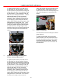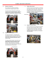
1
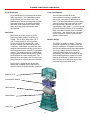
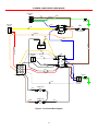
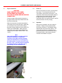
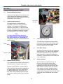
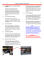
ID SERIES
CABLE DRYER
USER MANUAL
Bulletin AE01B-A0514-001
Rev: C
Date: 6 FEB 07
ID SERIES CABLE DRYER USER MANUAL
SECTION 1
General Information
Introduction
Specifications
Description and Diagram
Electrical Diagrams, Front Panel
Electrical Diagrams, Chassis
4
4
4
6
8
9
SECTION 2
Installation
Conduit Attachment
Installation of Pedestal
Optional Slab Mount Pedestal Drain (AE01K-A0853-001)
Installation of Air Dryer Module
Dryer connections
Power up
Pressure Regulation
10
10
10
11
11
12
12
12
SECTION 3
System Pressure
System (output) pressure
Membrane Back Pressure
Cable dryer Duty Cycles
Hour Meter Display
Alarm Conditions
Programming Information
Full Alarm Option
Humidity Bypass Option
Alarm Definitions
Alarm PWB Diagram
13
13
13
13
13
13
14
14
14
15
16
SECTION 4
Theory of Operation
17
SECTION 5
Maintenance
Semi-Annual Maintenance
3000 Hour Overhaul
Cable Dryer Overhaul Kit
Semi-Annual Preventive Maintenance Inspection
Check Water Filter and Coalescent Filter and Elements
Check Electrical Connections
Check Ground Wire
Check Run Time Meter
Replace Compressor Air Filter
In Case of Difficulty
17
17
17
17
17
18
18
18
18
18
18
SECTION 6
Troubleshooting
19
ID SERIES CABLE DRYER USER MANUAL
SECTION 7
Replacement Procedures
Parts Replacement Procedures
Unit Shutdown and Removal
ID3000 Dryer Module Replacement
Replace Power Switch
Replace Circuit Breaker
Replace Compressor or Remove Compressor for Overhaul
Replace First Stage Coalescing Filter Element - 3000 hour Maintenance
Replace Second Stage Coalescing Filter Element - 3000 hour Maintenance
Replace Thermostats
Replace Cooling Fan
Replace Heater Elements
Replace Alarm Board
Replace Pressure Switch
Solenoid Valve
Replace Pedestal Filters
20
20
20
20
20
20
21
21
22
22
23
23
23
23
24
24
SECTION 8
Parts List
Maintenance Items
Replacement Components
25
25
25
SECTION 9
Customer Support
24 hour Technical Service Hotline
Free Loaner Program
26
26
26
SECTION 10
Warranty
27
ID SERIES CABLE DRYER USER MANUAL
SECTION 1
General Information
Specifications for In-ground Automatic
Membrane Cable Air Dryer
ID3000 In-ground Automatic Membrane
Cable Air Dryer
Output capacity
Now technicians and managers can be assured
of reliable pressurization of underground cables
even at remote locations. The new ID3000
Cable Air Dryer from Andrew Corporation uses
proven, patented membrane drying technology
for a consistent, precise supply of dry air.
Electrical power requirements phase
The ID3000 Cable Air Dryer comes in a
standalone compact, unobtrusive pedestal
enclosure, delivering reliably dry air in a more
scientific, efficient, and quiet method. Service
calls to the remote locations can be greatly
reduced with the unique quick exchange dryer
module. The ID3000 is the sensible choice
to extend cable life and avoid costly service
interruptions from moisture ingress.
Up to 68,000 SLPD (@69 kPa)
2,400 SCFD (@10 psi)
115/230 Vac, 50/60 Hz 1
Exposed length,
85.1 cm (33.5 in)
Exposed width,
58.4 cm (23.0 in)
Exposed height,
64.8 cm (25.5 in)
Dewpoint
-45° C (-50° F)
Output pressure
0-105 kPa (0-15 psig)
Low pressure alarm.
7 kPa (1 psig), or as required
High humidity alarm
>7.5% RH, factory set
Features:
•
Exceptional performance: dew point of better
than -45° C, (-50° F)
Excess runtime alarm
•
Eliminates nitrogen bottles and associated
maintenance
Internal Front Mounted Controls, Status Indicators
•
Fully automatic with regulated output
•
Unobtrusive appearance
•
Easy setup and direct access
•
Environmentally proven enclosure material
•
Patented membrane drying eliminates drying
media
•
Quiet operation from oil-free compressor
•
Two-stage air particulate filtration to 0.01 micron
•
Full alarms option for remote monitoring of
system conditions
Standard Low-Pressure Alarm
•
Secure, lockable enclosure
•
No exposed air lines or components
•
3 year warranty
User selectable in minutes
Power fail alarm
Loss of input power
The ID3000 pressure gauge registers both
metric and Imperial units. It also provides a resettable circuit breaker, a black ON/OFF switch,
a compressor runtime meter, and an integral 2
port manifold with automatic shut off valves.
Electrical Connections
Use ID Series Air Dryers anywhere in the world.
The AC input is factory selectable for 115/230
Vac and the compressor is rated for both 50
and 60 Hz operation. Each unit is supplied with
a terminal strip for mains power connection
located on the internal front panel for easy
access. Route mains power into conduit directly
underground to eliminate exposed wiring.
The ID3000 Air Dryer includes a low-pressure
alarm which closes at 1.0 psi (7 kPa). An
optional alarm package adds a high humidity
alarm (>7.5 RH), a user adjustable excess
runtime alarm, and a power fail alarm.
ID SERIES CABLE DRYER USER MANUAL
2 Port Distribution
Front Panel Features:
Dry air distribution is incorporated into the basic
cable dryer design. Two independent outputs
are provided on the front interior of the unit.
Bulkhead quick-disconnect fittings with integral
valves are supplied on the cabinet polytubing
connection to the underground cables. Each
end of the tubing seals automatically when
disconnected.
Description:
The ID3000 Air Dryers provide dry air for
pressurizing cable systems contained in a
conduit. The Air Dryer will produce -45° C
(-50° F) dewpoint dry air at an output rate
of up to 68,000 SLPD (2400 SCFD). Each
Air Dryer consists of an electrically driven air
compressor, a membrane dryer assembly, and
automatic cable pressure sensing system and a
monitoring/alarm system housed in a rigid metal
chassis. The chassis is fitted to a molded high
strength plastic pedestal designed to be partially
buried adjacent to a cable access point. The
pedestal has a removable cover for easy access
and provisions for a locking device are included.
The front panel contains all of the
instrumentation necessary to operate and
monitor the performance of the ID3000 Air
Dryer. The front panel features a power switch,
a pressure gauge and a flow meter to monitor
the output pressure and flow rate of dry air
supplied to the cable system. A pressure gauge
to monitor the back-pressure in the membrane
dryer is provided to assure proper membrane
performance. Also located on the front panel
are the compressor run time meter and a resettable circuit breaker.
Modular Design:
The Air Dryer is equipped with an automatic
heating and ventilation system that allow it to
operate outdoors in extreme weather conditions.
Pedestal Cover
Pressurization Module
Tank Assembly
Pedestal Base
Grade Line
The ID3000 is modular in design. The main
enclosure or pedestal, the reservoir tank and
the dryer module are all separate components
and can be installed and serviced independently. This unique feature allows the ID3000 an
unparalleled advantage when it comes to
field service. The main dryer module can be
removed and replaced in a matter of minutes
allowing the technician to spend a minimum
amount of time in the field servicing the dryer
and minimizing system down time.
ID SERIES CABLE DRYER USER MANUAL
Tank Valve
(pressure monitoring)
Pressure Regulator
Membrane Dryer
Cartridge
Flow Meter
Oil Free Compressor
Power Switch
Hour Meter
Pressure Gauge
Lift-out Dryer Chassis
Power Terminals
LED Alarm Indicators
Alarm Terminals
Air Outlet
(quick disconnect and
automatic shut-off)
Backpressure Gauge
Air Storage Tank
Buriable Enclosure
Figure 2. ID3000 with cover removed
ID SERIES CABLE DRYER USER MANUAL
Notes:
ID SERIES CABLE DRYER USER MANUAL
MAIN POWER
TB1
N
GND
GRN/YEL
2
BRN
1
L
CHASSIS
ON ALARM
BOARD
26
1 2 3
BLU
1
4
5
2
25
4
E1
CB1
BRN
20A
CIRCUIT BREAKER
POWER SWITCH
ORN/WHT
S1
ORG
14
BLU
6
BRN
HOURMETER
M1
ORG
15
GND
2
2
BLK
1
6
5
4
9
8
7
B
BLK
21
A
18
A
19
PRESSURE
SWITCH
20
BRN
BLK
3
B
17
BLU
WHT
J3
S2
16
LINE
WHT
1
ON ALARM
BOARD
5
MOTOR
27
RED/WHT
RED
CONNECTOR
11
GRN/YEL
12
C2
10
THERMOSTAT
9
BLK
T1
8
THERMOSTAT
22
BRN
BLK
T2
7
Figure 3. Front Panel Wire Diagram
2
1
4
3
6
5
J5
ON ALARM
BOARD
WHT
BLK
J9
3
YEL
13
CHASSIS
E1
ID SERIES CABLE DRYER USER MANUAL
SOLENOID
VALVE
SOLENOID
VALVE
SOLENOID
VALVE
SV1
SV2
SV3
1
2
1
2
1
2
ORN/WHT
67
ORN
55
GRN/YEL
53
57
68
RED/WHT
RED
CHASSIS
54
E1
ORN
BLK
1
52
B1
2
51
WHT
COMPRESSOR
FAN
F1
60
SPLICE
1
59
SPLICE
62
2
61
FAN
WHT
63
3
2
1
RED
F2
SPLICE
56
1
2
3
4
5
6
7
8
9
2
CONNECTOR
58
1
WHT
2
C1
HEATER
BLK
H1
65
BLU
BRN
66
H2
HEATER
Figure 4. Chassis Wire Diagram
64
ID SERIES CABLE DRYER USER MANUAL
SECTION 2
Installation
2.0
Conduit Attachment
Install conduit fittings for air and electrical
connections in bottom of Air Dryer pedestal as
shown. Feed electrical wiring, safety ground
wire, alarm wiring and air tubing through the
conduit and expose approximately 91 cm (36 in)
of each into the unit pedestal for termination to
air dryer module. The electrical wiring should
be per electrical code. Alarm wiring should be
8-conductor shielded cable, 20 or 22 awg. Air
tubing is 3/8” O. D. polyethylene and is included
with the unit.
2.3
Optional equipment:
The ID3000 is designed to accept commercial
power provided by a locally available power
meter. Where the power meter is not equipped
with a disconnect the Andrew pole mounted
disconnect P/N: AE01J-A2030-050 can be
installed to provide this feature. The disconnect
in mounted to a 122 cm (48 in) pole with ground
line markers at 46 cm and 61 cm (18 in and 24
in). There are 2 breaker slots in the disconnect
box that can be used to provide power to the
ID3000 and to a convenience outlet if required. These breakers should be installed by a licensed
electrician in accordance with local code. A 20
amp breaker is recommended for the ID3000
and the appropriate gauge wire for the breaker
size should be used to meet local codes.
2.4
Connection:
All electrical mains connections should be
performed by a licensed electrician.
Install the disconnect adjacent to the ID3000. Install circuit breaker in disconnect enclosure. A
20 amp breaker is recommended. Route power from the meter to the disconnect
via an underground conduit. 2.1
Installation of Pedestal
Connect the mains power to the disconnect. Excavate the ground for placement of the
pedestal 114.3 cm x 63.5 cm x 36.8 cm (45 in
x 25 in x 14.5 in) deep with conduit trench 15.3
cm (6 in) wide x 50.8 cm (20 in) deep. Place
pedestal / conduit assembly in hole, aligning
conduit in trench. Level the pedestal and repack
and level the soil around the perimeter. Some
location may require gravel in the bottom of the
hole proper drainage.
Route conduit from disconnect to ID3000 via
an underground conduit. Connect conduit to
bottom of ID3000. Route power wires through conduit and connect
to the ID3000.
10
ID SERIES CABLE DRYER USER MANUAL
2.5
Optional Slab Mount Pedestal Drain (AE01KA0853-001):
Drill 12.7 mm (1/2 in) hole in bottom of pedestal
adjacent to conduit connectors, Install drain
vent.
NOTE:
This drain is only used for pedestals
mounted above grade.
Drill 12.7 mm
(1/2 in) hole.
2.6
Installation of Air Dryer Module
Lift and remove pedestal lid from base and
set aside. Place included air tank in the
bottom of pedestal base, avoiding air and
electrical lines. Set the air dryer module into
opening in pedestal base, aligning pins on
the dryer with holes in base.
Solenoid
drain hose
11
ID SERIES CABLE DRYER USER MANUAL
2.7
Dryer connections
2.8
Power up
CAUTION:
MAKE CERTAIN THAT POWER
IS DISCONNECTED FROM THE
ELECTRICAL WIRING BEFORE MAKING
CONNECTION.
After all connections are secure, provide power
to the dryer. Turn the power switch to the
“ON” position (on front face of the dryer). The
compressor should start and the back pressure
gauge on the dryer module should increase
to approximately 297 kPa (43 psig). The
compressor will run for several minutes, until the
air tank is filled to 276 kPa (40 psig).
2.9
Operation
After set up is complete, the unit is ready for
operation. Replace lid onto pedestal base
and secure as desired. The pedestal comes
standard with a hex bolt closure device. The
closure has provisions for a padlock which
prevents access to the to the hex bolt closure.
Pentagonal head or other tamper resistant
closures are available on request.
Provide a proper safety ground connection to
the ground stud on the dryer chassis below the
electrical terminal strip.
Make electrical power connections and alarm
connections to dryer terminal strips. Make tank
air connections using quick-connect fittings
from tank air lines to ports on dryer marked “TO
TANK” and “FROM TANK”. Make output air
connections using quick-connect fittings from
conduit to ports on dryer marked “LINE 1” and
“LINE 2”.
Note
After initial installation and after extended
periods of inactivity (ie: compressor
overhaul) run the dryer until the humidity
alarm has cleared prior to connecting it to
the cable system. In some cases this could
be up to 1 hour. This time may be shortened
by running the dryer in the shop prior to
transporting it to the installation site.
12
ID SERIES CABLE DRYER USER MANUAL
SECTION 3
Pressure Monitoring and Control
3.0
Pressure Monitoring Points
Cable dryer output pressure is monitored at the
output regulator and displayed on the gauge
located on the front panel (labeled as “SYSTEM
PRESSURE), refer to figure 2.
3.1
System (output) pressure
The output pressure is controlled by an
adjustable 0-103 kPa (0-15 psig) pressure
regulator. The regulator is located directly
behind the power switch. To adjust the output
pressure, loosen the lock nut and turn the screw
on top of the regulator (clockwise to increase)
then tighten the lock nut to lock the set point.
Back pressure
PPV valve
Note:
To set the output pressure, the output
line must be blocked. To block the output
line, simply remove the “TO SYSTEM” air
connections. They are valved to block flow
when removed.
3.3
Cable dryer Duty Cycles
The cable dryer is programmed at the factory
to start when the reservoir tank pressure drops
to 103 kPa (15 psig) and stops when the tank
pressure reaches 276 kPa (40 psig).
3.4
Hour Meter Display
This shows the total run time for the compressor
since it was built. The total run time should be
monitored to determine the duty cycle of the
cable dryer and for compressor maintenance
scheduling. No adjustments are necessary and
none are provided.
3.5
Alarm Conditions
Alarm conditions, except Excess Run, are
factory set and cannot be altered. Alarm
contacts are included in the unit and wiring
terminals are located on the inside of the door.
When an alarm condition exists, the normally
open contacts are closed, thereby activating
a remote alarm (not included). Also the alarm
condition will be displayed on the series of LED’s
on the front panel (included with the full alarm
option).
Screw
Jam Nut
3.2
Membrane back pressure
The membrane back pressure is set at 297 kPa
±43 (50 psig ±5). It is preset at the factory.
Membrane back pressure is monitored at the
outlet of the dryer cartridge and is displayed on
the gauge located on the front panel (labeled
as “BACK PRESSURE), refer to figure 2. A
tank valve is also provided on the back of the
front panel for testing pressure with a separate
gauge.
13
ID SERIES CABLE DRYER USER MANUAL
3.6
Programming information
Excess Run Time Alarm Setting JP1, refer to
figure 6. The cable dryer will signal an alarm
condition when the cable dryer operates longer
than the selected time, in minutes. The alarm
indicates that there is either a substantial
leak in the system or that the cable dryer is
not supplying a sufficient volume of dry air.
The initial factory setting is 120 minutes. The
alarm should be set for a time about twice the
anticipated normal running time.
Also located on the front panel (with the full
alarm option) are LED status/alarm indicators
for power, compressor activity, high humidity,
excess run and low pressure and a terminal strip
for connection of a remote monitoring system
(not included) to Form C dry contact alarm indicators.
The external alarm monitoring system (not included) is connected to the terminal strip located
on the front panel. A small slotted screwdriver is
necessary to make the connections.
Note:
To clear the Excess Run alarm turn the
power OFF and then ON.
The connection to the alarm strip is as follows,
refer to figure 5 for correct locations and colors
of the wires on the terminal strip.
When removing your cable dryer from
service, you may need a substitute dry air
source. Call Andrew Technical Service.
Telephone numbers are listed in Section 9.
3.8
Humidity Bypass Option
The humidity bypass feature is optional with the
full Alarm option. This feature diverts air flow
into the atmosphere if the high humidity alarm
is active. This prevents feeding humid air into
the pressurized lines. When the humidity alarm
clears, the output air is automatically channeled
back to the pressurized lines.
Before turning OFF the unit, notify alarm
monitoring personnel that alarms may be
activated.
To shut down the ID Series unit, turn the ON/
OFF power switch to the OFF position and close
the isolation shutoff valves located in the output /
input lines to retain system pressure.
Disconnect by releasing the quick-connect air
fittings on the front panel. Air output(s) labeled
“TO SYSTEM” are the output line(s). Air
connections labeled “TO TANK” and “FROM
TANK” are connections to the air reservoir tank.
These fittings may be under pressure.
CAUTION:
USE CAUTION WHEN REMOVING
OR REPLACING AIR CONNECTIONS.
PRESSURE MAY BE PRESENT
WHETHER THE UNIT IS ON OR OFF.
3.7
Full Alarm Option
This optional assembly is designed to provide
the additional Excess Run, High Humidity and
Power Fail alarms to Andrew Cable dryers. All
alarms are Form C dry contacts and are factory
set for continuity at alarm.
14
ID SERIES CABLE DRYER USER MANUAL
3.9
Alarm Definitions:
Low Pressure:
If system pressure falls significantly below the
low-pressure trigger point, the low-pressure
alarm sensor will activate an alarm contact. This alarm is an indication of a significant
system leak or a cable dryer failure.
Excess Run:
User settable run time to be set in accordance
with the normal run time for the particular
application. Selectable times are 10, 30, 120
and 240 minutes. Refer to figure 6 for location
of JP3.
Power Fail:
Activates when power is removed from the cable
dryer. This includes turning the power OFF at
the switch.
High Humidity:
Activates when system or cable dryer output
humidity rise above 7.5% relative humidity. At initial installation, this alarm will continue
to alarm until the system has been properly
purged.
AUX:
Auxiliary alarm not used with the ID3000
Figure 5. Alarm Terminal Connections
15
ID SERIES CABLE DRYER USER MANUAL
J2
Press. Switch
PS2
J3
Time Connection
JP3
Compressor Voltage
Timer Set (120v)
JP1
Compressor Excess
Alarm Timer (10 min.
J4
Humidity Sensor
JP2
J1
Power Selector
Input
AC - (A-B)
DC - (B-C)
Press. Switch
PS1
J6
Alarm LED
J9
F1
Humidity Bypass
Solenoid
Fuse
J7
Term Block
Connector
J5
JP6
Main Power
Low Press. (A-B)
N.O.
JP7
Power Alarm (B-C)
N.C.
JP9
Humidity Alarm (A-B)
N.O.
JP5
Aux (A-B) N.O.
JP8
Compressor Timer
Figure 6. Changing Alarm Outputs:
Term.
1
2
3
4
5
6
7
8
9
10
Function
Power Fail Com
Power Fail Alarm
Humidity Com
Humidity Alarm
Excess Run Com
Excess Run Alarm
Low Press. Com.
Low Press. Alarm
Not used
Not used
Wire Color
Black
Red
Green
Brown
Blue
White
Grey
Orange
N/A
N/A
NO Power
Normal
Alarm
OFF
ON
OFF
OFF
OFF
ON
OFF
OFF
ON
ON
OFF
ON
N/A
N/A
N/A
ON = Conducting as factory set
OFF = Non-conducting as factory set
Table 1. Changing Alarm Outputs:
16
ID SERIES CABLE DRYER USER MANUAL
SECTION 4
Theory of operation
SECTION 5
Maintenance
The patented drying system begins at the compressor,
where filtered ambient air is compressed. The
compressed air is then cooled and condensed in the
heat exchanger after which water droplets are separated
in the water filter. The saturated air then passes through
a coalescing filter for the removal of additional water and
then into the patented membrane cartridge where the
remaining water is removed by pressure differential.
5.0
The cable dryer requires maintenance
semiannually and after each 3000 hours of
operation to ensure continued reliable operation.
Service personnel should observe all
safety regulations. Do not perform
maintenance on equipment without
first turning OFF the main power
supply. Under certain conditions,
dangerous potentials may exist when
the main power supply controls are
in the OFF position. Only qualified
technicians should attempt to effect
maintenance or repairs on electrical
equipment.
5.1
Semi-Annual Maintenance.
The semi-annual maintenance consists of
a preventive maintenance inspection and
replacement of the compressor air filter. These
tasks can be performed easily in the field as
described below.
5.2
3000 hour Overhaul.
A cable dryer overhaul is required after the
compressor has run a total of 3000 hours, as
indicated on the compressor run time meter. The cable dryer overhaul includes a compressor
overhaul, water filter, high temperature tubing
and hose clamps.
5.3
The cable dryer overhaul kit,
See Section 7.7 includes all the necessary parts
and instructions. Or, if you prefer, Andrew offers
a cable dryer overhaul service. Contact Andrew
Technical Service. Telephone numbers are
listed in Section 9.
5.4
Semi-Annual Preventive Maintenance
Inspection
Inspection includes checking for loose
or damaged hoses, fittings and electrical
connections.
Check the following items:
The water separated in the filters is exhausted through
the unit side vents. The purging of this condensate is
controlled by solenoid valves mounted in the chassis and
discharged through a port adjacent to the exhaust fan. The valves are energized only when the compressor is
running.
The membrane cartridge separates moisture from air
by a pressure differential across semi-permeable fibers. The water vapor and a small amount of the air permeate
through the filter walls leaving the exiting air with a
reduced water vapor content of -45°C (-49°F) dewpoint. The air that permeates through the fibers purges the
water vapor out of the cartridge’s vent ports.
This patented dryer contains no moving parts, thus
reducing maintenance and increasing reliability.
In order to provide a constant supply of dry air and to
maintain an acceptable moisture level in the product
air stream, a high-pressure reservoir tank is used. The
reservoir tank is connected to an adjustable regulator
and orifice to allow a controlled flow at up to 103 kPa
(15 psig). In addition to supplying the output air, the
reservoir tank also provides the dry air for the feedback
loop. The feedback loop eliminates the need for a high
humidity bypass valve. The feedback loop utilizes a very
small portion of the dry output air to keep the membrane
dry and ready to provide dry air on demand.
During normal operation, the bleed air in the feedback
loop will cause the pressure to drop in the reservoir tank
and the ID3000 compressor will cycle automatically. These cycles will take place regardless of the volume or
condition of the cable system. The rate of these cycles,
however will vary depending on the flow require to
maintain the desired pressure in the cable system.
17
Danger
ID SERIES CABLE DRYER USER MANUAL
5.5
Check Water Filter and Coalescent Filter and
Elements
Verify there is no water build-up in the
filter bowls. If there is water, refer to the
troubleshooting procedures in Section 6 for
corrective action. Replacement of the water
filter and coalescent filter and their associated
elements and bowls is covered in the parts
replacement section of this manual. Refer to
Section 7.
5.6
Check Electrical Connections
Check for loose or corroded electrical
connections. A loose terminal can cause erratic
operation and unnecessary downtime. Check
the screw-on and push-on terminals and tighten
as required.
5.7
Check Ground Wire
Check for proper ground wire connection to
protect operations personnel. A green ground
wire is attached between the power terminal
strip and the cable dryer chassis. The ground
lug screw or stud nut must be tight to provide a
proper ground.
5.8
Check Run Time Meter
Check the run time meter to determine the duty
cycle of the cable dryer. If the cable dryer has
been running more than 30% of the time, check
for system leaks. Also check to see if it is time
to schedule the 3000 hour maintenance.
5.9
Replace Compressor Air Filter
The air filter protects the compressor from
contamination and extends the service life of
the compressor. It is made of open cell material
and should be replaced every six months or
more often if the cable dryer is located in a dusty
environment.
Air filter
18
Carefully pull off the filter cover (twist/pull) and
remove the filter element. Install the new filter
element and replace the filter cover, being
certain that it is completely seated. To replace
the filter housing, unscrew the housing from the
compressor head and replace with new filter
housing.
5.10
In Case of Difficulty
If you experience difficulty with your cable dryer,
use the troubleshooting procedures described
below. Perform the tests, inspections and
corrective actions corresponding to the problem
in the order listed. Refer to figure 3 and 4 for
wiring. Section 8 lists replaceable parts.
Andrew Technical Service. If you cannot correct
the problem or if there are other difficulties,
contact the Andrew Technical Service nearest
you. Telephone numbers are listed in Section 9.
After initial installation and after extended
periods of inactivity (ie: compressor
overhaul) run the dryer until the humidity
alarm has cleared prior to connecting it to
the cable system. In some cases this could
be up to 1 hour. This time may be shortened
by running the dryer in the shop prior to
transporting it to the installation site.
High voltage exists inside the
unit. Disconnect the unit whenever
performing troubleshooting operations.
Note
Caution
ID SERIES CABLE DRYER USER MANUAL
SECTION 6
Troubleshooting
Table 2. Troubleshooting Procedure
Problem/Condition
Solution
Check the breaker adjacent to the ON/OFF switch if, tripped (white
indicator exposed) then reset breaker.
Cable dryer power LED does not light, unit
does not run.
If power switch light still fails to light, make sure that unit is plugged in
and the power outlet is operating.
If you still have no light, disconnect electrical power, and check for loose
connections. Refer to wiring diagram for proper wire connection.
Cable dryer starts and stops before reaching
sufficient line pressure.
Low pressure alarm LED illuminated.
Check for kinks in line tubing. Replace tubing where necessary.
Check output lines. Make sure any isolation valve is wide open.
Check output lines. Make sure any isolation valve is wide open. Check
“TO SYSTEM” output fitting(s). If not securely connected, internal
valving can block flow.
Isolate the low pressure condition by checking all fittings with soapy
water. Make sure that all system tubing is properly seated in the fittings. Check for loose interface points and holes in the lines. Correct any
conditions that exist where pressure is leaking. If the condition persists,
call Andrew Technical Service for assistance.
Check the cable dryer for build-up of water in the filter bowls.
If there is a build-up of water in the water filter bowl, use a soapy
water solution to check for leaky fittings in the cable dryer. Also, check
to assure that the filter drain solenoid valves are closing when the
compressor runs, and venting when the compressor turns off. If no leak
can be found, the problem is probably with the compressor. Rebuild
CAUTION:
kits for each cable dryer are specified in section 7. The unit may also
The humidity sensor is light sensitive. be returned to Andrew for repair. Contact Andrew Technical Service for
further assistance.
DO NOT remove it from the brass
fitting when the cable dryer is
NOTE:
powered up.
The PPV is preset and should not be adjusted unless the back
pressure is outside of 43 psi +/- 5 psi.
Humidity alarm on display.
Excess run time alarm LED Illuminated.
Check system for leaks. See troubleshooting section “Low pressure
alarm on LED illuminated”.
Cable dryer turns on for only a few seconds,
and then shuts off.
Check the AC voltage supply to the unit
No output flow or pressure.
Compressor relief valve pops.
Check regulator setting.
Check tank connections for proper insertion.
Check “TO TANK” connection.
Check “TO TANK” connection
19
ID SERIES CABLE DRYER USER MANUAL
SECTION 7
Replacement Procedures
7.0
Parts Replacement Procedures
When the cable dryer run time reaches 3000
hours, it will be necessary to rebuild the
compressor and replace the hoses, clamps,
water and coalescent filter elements. The
necessary parts and instructions are included in
the over haul kit, listed in Section 8.0.
Following are procedures for replacement of the
parts listed in Section 8.0.
7.1
Unit Shutdown and Removal
In order to perform parts replacement on the
ID3000 Cable dryer, it will be necessary to turn
OFF the unit and remove it from service. As
this is done, one or more of the alarms may be
activated. Personnel who may be monitoring
these alarms should be informed prior to the
units being turned OFF. It will also be necessary
to close off the lines connected to the cable
dryer to avoid losing pressure in these lines. Once these steps have been taken, turn OFF
the power to the unit, disconnect the alarm
connections and unplug the unit. The units can
now be moved to a suitable work area for parts
replacement.
7.2
ID3000 Dryer Module Replacement
Turn OFF electrical power at main breaker. Disconnect electrical power from ID3000 by
removing wiring from screw terminals on front
panel or by disconnecting power cord from
plug. Disconnect alarm wiring from terminal
strip. Note colors for re-connection. Release
quick connect air fittings from “TO SYSTEM”,
“TO TANK” and “FROM TANK” connections. Dryer module can then be lifted directly pedestal
enclosure. A new module may be dropped in
and connections reestablished.
20
7.3
Replace Power Switch
Disconnect the four terminals from the power
switch, carefully noting the location of each wire. Compress the retainers on the switch and push
the switch out the front of the chassis. It may be
necessary to rock the switch from top to bottom
to remove it. Replace switch, by snapping it in
place. Reconnect the four wires.
7.4
Replace Circuit Breaker
The circuit breaker is located on the upper
front door of the cable dryer. Disconnect the
two terminals from the circuit breaker, carefully
noting the location of each wire.
To remove the circuit breaker, compress the
retainers on both sides and push it through the
front panel opening. Replace circuit breaker,
snapping it in place. Reconnect the two wires.
ID SERIES CABLE DRYER USER MANUAL
Compressor
output hose
7.5
Replace Compressor or Remove Compressor
for Overhaul.
Remove dryer module from pedestal enclosure
for easy access, refer to section 7.2 for
instructions. To access the compressor, remove
the membrane dryer assembly by removing
two screws from each side of the dryer bracket. Disconnect tubing from the membrane dryer
assembly and set aside. Remove output tubing (milky white) from compressor. Remove the four
nuts securing the compressor to the vibration
isolator. Remove the wiring access plate from
the end of the compressor and disconnect
wires. Note wire locations for re-connections. Reverse these steps to replace compressor. For
actual compressor, refer to compressor manual
included with this manual.
Access to
compressor wire
connection
Dryer mounting
screws
21
Compressor
mounting nuts
7.6
Replace First Stage Coalescing Filter
Element - 3000 hour Maintenance
Replace the coalescing filter after each 3000
hours of operation.
The coalescing filters are located downstream
from the heat exchanger. Their function is to
remove any “water vapor” which may still be
present in the air leaving the heat exchanger. The first coalescing filter (1.0 micron) and the
second coalescing filter (0.1 micron) trap any
fine liquid water particles, including aerosols
and cause them to coalesce into larger droplets.
These droplets fall to the bottom of the bowl and
vented out of the unit.
ID SERIES CABLE DRYER USER MANUAL
To replace the filter element, twist and remove
the filter bowl from the cast housing. Unscrew
the filter element from the cast filter housing and
replace with a new filter. Do not attempt to clean
the filter element. If it is necessary to clean the
filter bowl, use a mild soap and water solution
and rinse with water. Do not use solvents. Reassemble the unit by reversing the above
procedure. Check for leaks by turning the unit
ON and applying a dilute detergent and water
solution at the bowl/housing seal and at the hose
fittings which were reconnected. If no leaks
are found, the unit is ready to return to service. If leaks are located, repair the leak and recheck
for additional leaks. Leaking fittings must be
repaired or the unit will not function properly and
can result in damage to the transmission line
system.
7.7
Replace Second Stage Coalescing Filter
Element - 3000 hour Maintenance
To replace the filter element, twist and remove
the filter bowl from the cast housing. Unscrew
the filter element from the cast filter housing and
replace with a new filter. Do not attempt to clean
the filter element. If it is necessary to clean the
filter bowl, use a mild soap and water solution
and rinse with water. Do not use solvents. Reassemble the unit by reversing the above
procedure. Check for leaks by turning the unit
ON and applying a dilute detergent and water
solution at the bowl/housing seal and at the hose
fittings which were reconnected. If no leaks are
found, the unit is ready to return to service.
22
If leaks are located, repair the leak and recheck
for additional leaks. Leaking fittings must be
repaired or the unit will not function properly and
can result in damage to the transmission line
system.
7.8
Replace Thermostats
The thermostats control the cooling fans and the
heater elements. To replace a thermostat, remove wires from
spade terminals on the thermostat and remove
the nuts and washers securing it to the chassis
and discard defective thermostat. Secure the
new thermostat with the nuts and washers and
reconnect wires.
ID SERIES CABLE DRYER USER MANUAL
7.9
Replace Cooling Fan
7.11
Replace Alarm Board
The cooling fans ventilate the pedestal
enclosure thus cooling the dryer module
To remove the fan, disconnect the fan leads
and remove the mounting hardware. Install the
replacement fan using the existing hardware.
Orientation of the AC power leads is not critical.
On the front panel of the cable dryer, disconnect
the wiring from the alarm board, carefully noting
the location of each connector. Remove the
hardware which secures the alarm board to the
door panel. Install the replacement alarm board
by reversing the above process.
Alarm Board
7.10
Replace Heater Elements
The heater elements are controlled by the
thermostats located on the inside of the front
panel and prevent the formation of ice in critical
areas when the ambient temperature drops
below freezing.
To replace heater elements, remove the nuts
and washers securing the retaining bracket. Disconnect the heater wires from the wire
harness. Connect wires from new heater
elements to wire harness and secure the heater
element with the retaining bracket.
Heater Elements
23
7.12
Replace Pressure Switch.
On the front panel of the cable dryer disconnect
the wiring from the pressure switch, carefully
noting the location of each lead. Remove the
hardware that secure the switch to the panel. Install the replacement switch by reversing the
above procedure.
ID SERIES CABLE DRYER USER MANUAL
7.13
Solenoid Valve
7.14
Replace Pedestal Filters
Adjacent the compressor on the right side,
locate the two solenoid valves. To replace,
remove the electrical spade connections
and release the air tubing from the barbed
connections. Remove the hardware that
secures the valve, and lift. To replace, reverse
the above steps.
Remove Pedestal cover, disconnect and remove
dryer module from the pedestal. Using a flat
blade screwdriver carefully remove the (4) snap
fasteners from the filter mounting block on each
side of the pedestal Remove the filter mounting
block from inside the pedestal. Remove and
replace the metal mesh filter discs from the filer
blocks. Replace the filter blocks by reattaching
the snap fasteners. Reinstall dryer module and
cover.
The pedestal filters should be inspected
and replaced once per year. Dust or salt
laden environments may require more often
maintenance.
24
ID SERIES CABLE DRYER USER MANUAL
SECTION 8
Parts List
Table 3. Maintenance Items
Description
Part Number
Dryer Module w/ Full Alarms, w/ Humidity Bypass
Dryer Module w/ Full Alarms
Dryer Module w/ Low Pressure Alarm only
Pedestal Enclosure Only
Tank Assembly Only
Complete Overhaul Kit
Filter Screen Kit (Enclosure Filters)
Replacement Tubing Kit
Filter Media (5.0 micron, water filter)
Filter Media (0.01 micron, Coalescing Filter)
Filter Bowl
Compressor Intake Filter Media
ID3000-89415-100
ID3000-89315-100
ID3000-89015-100
ID3000-89315-200
ID3000-89315-300
AE01K-C0398-019
AE01K-A0848-001
AE01K-A0849-001
EFLTA-94045
EFLTA-94044
EFLTA-94041
46173-1
Table 4. Replacement Components
25
ID SERIES CABLE DRYER USER MANUAL
SECTION 9
Customer Support
9.0
24 Hour Technical Service Hotline
Andrew maintains a Technical Service Hotline
for assistance with product repairs and service.
Andrew Corporation
10500 West 153rd Street
Orland Park, IL U.S.A. 60462
Telephone: 708/349-3300
FAX (U.S.A.): 1-800-349-5444
Customer Support Center
From North America
Telephone: 1-888-889-9485
International
Telephone: +1-708-873-2307
Fax: +1-708-349-5663
Internet: www.andrew.com
9.1
Free Loaner Program
Andrew maintains a repair center for
pressurization equipment. Free loaner units are
available for use while your equipment is being
repaired by Andrew. Call our Technical Service
Hotline for details.
26
ID SERIES CABLE DRYER USER MANUAL
®
Andrew Corporation
Cable Dryer Series Large Capacity
Dehydrator System
Three Year Limited Warranty
Seller warrants that any Andrew ID3000, CO5k, CO30/60K, and Trailer Series
number type DryLine® Dehydrator is transferred rightfully and with good title;
that it is free from any lawful security interest or other lien or encumbrance
unknown to Buyer; and that for a period of thirty-six months (36) months from
the date of installation or 3000 hours of actual run time (except for the
compressor which is for a period of twelve (12) months or 1000 hours,
whichever shall occur first, such equipment will be free from defects in material
and workmanship which arise under proper and normal use and service.
Buyer's exclusive remedy hereunder is limited to Seller's correction (either at its
plant or at such other place as may be agreed upon between Seller and Buyer)
of any such defects by repair or replacement at no cost to Buyer; provided that
the cost of any transportation in connection with the return of the equipment
for the purpose of repair or replacement shall be borne by Buyer. Expressly
excluded from the terms of this warranty are defects caused by: (i) faulty
installation, (ii) lack of proper inspection or maintenance, (iii) and usage not in
accordance with published ratings, specifications, or instructions.
The
provisions of this warranty shall be applicable with respect to any equipment
Seller repairs or replaces pursuant to it.
SELLER MAKES NO WARRANTY, EXPRESS OR IMPLIED, OTHER THAN AS
SPECIFICALLY STATED ABOVE. EXPRESSLY EXCLUDED ARE ANY IMPLIED
WARRANTIES OF MERCHANTABILITY OR FITNESS FOR PURPOSE. THE
FOREGOING SHALL CONSTITUTE ALL OF SELLER'S LIABILITY (EXCEPT AS
TO PATENT INFRINGEMENT) WITH RESPECT TO THE EQUIPMENT. IN NO
EVENT SHALL SELLER BE LIABLE FOR SPECIAL, CONSEQUENTIAL OR
INCIDENTAL DAMAGES, INSTALLATION COSTS, LOST REVENUE OR
PROFITS, OR ANY OTHER COSTS OF ANY NATURE AS A RESULT OF THE USE
OF THE EQUIPMENT MANUFACTURED BY SELLER, WHETHER USED IN
ACCORDANCE WITH INSTRUCTIONS OR NOT. UNDER NO CIRCUMSTANCES
SHALL SELLER'S LIABILITY TO BUYER EXCEED THE ACTUAL SALES PRICE
OF THE EQUIPMENT PROVIDED HEREUNDER. No representative is authorized
to assume for Seller any other liability in connection with the equipment.
07/06
27
ID SERIES CABLE DRYER USER MANUAL
®
Andrew Corporation
10500 W. 153rd Street
Orland Park, IL 60462 USA
One Company. A World of Solutions.
Customer Support Center
From North America
Telephone: 1-888-889-9485
International
Telephone: +1-708-873-2307
Fax: +1-708-349-5663
Internet: www.andrew.com
All designs, specifications and availability of products and services presented in this
bulletin are subject to change without notice.
Bulletin AE01B-A0514-001 (2/07)
© 2007 Andrew Corporation, Orland Park, IL 60462 USA