1
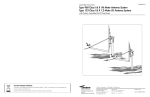
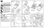
Assembly Instructions
8000284-01
90cm, 1.0m & 1.2m SMC Antenna System
with Az/El Cap Mount
TYPE 900 - 90cm
TYPE 100 - 1.0m
TYPE 120 - 1.2m
SMC ANTENNA WITH AZ/EL CAP MOUNT
Andrew
Andre
w Corporation
Customer Support Center
10500 West 153rd Street
Orland Park, IL U.S.A. 60462
1315 Industrial Park Drive
Smithfield, NC 27577 USA
Telephone: +1-919-989-2205
Fax: +1-919-989-2200
Internet: www.andrew.com
Printed in U.S.A.
ECN 9006666
5/04 8000284-01
VSAT ANTENNA/MOUNT/LNB
LIMITED TWELVE (12) MONTH WARRANTY
DATE
DESCRIPTION
REV.
2/26/90
Changed Pages 4, 6, 7, 8, 9 and 10.
ECN 9001516
A
4/20/90
Changed Pages 3, 4, 5, 6, 7, 8, 9 & 10.
ECN 9001550
B
9/10/90
Changed Cover, Pages 1, 6, 7, 12 & 13.
ECN 9001616
C
11/19/90
Changed Cover, Pages 1, 3, 4, 5, 6, 7, 8, 0, 10, 11 & 13.
ECN 9001665
D
11/4/91
Changed Cover, Pages 1, 2, 3, 4, 6 & 8-18.
ECN 9001881
E
9/93
Changed Cover, Inside Front Cover, Pages 1, 4, 6, 7, 8, 9, 10 & 11.
ECN 9002250
F
10/94
Changed Cover and Page 1.
ECN 9002568
G
8/97
All Pages
ECN 9003587
H
8/02
Changed Pages 4, 6, 10 & 12
ECN 9006120
J
9/02
Changed Pages 4, 6, & 10
ECN 9006205
K
5/04
ECN9006666
This ANDREW CORPORATION® equipment is warranted to be free from defects in material and workmanship under normal use and
service. ANDREW shall repair or replace defective equipment, at no charge, or at its option, refund the purchase price, if
the equipment is returned to ANDREW not more than twelve (12) months after shipment. Removal or reinstallation of
equipment and its transportation shall not be at the cost of ANDREW except ANDREW shall return repaired or replaced equipment
freight prepaid.
This Warranty shall not apply to equipment which has been repaired or altered in any way so as to affect its stability or durability, or which
has been subject to misuse, negligence or accident. This Warranty does not cover equipment which has been impaired by severe
weather conditions such as excessive wind, ice, storms, lightning, or other natural occurrences over which ANDREWhas no control,
and this Warranty shall not apply to equipment which has been operated or installed other than in accordance with the instructions furnished by ANDREW.
Claimants under this Warranty shall present their claims along with the defective equipment to ANDREW immediately upon failure. Noncompliance with any part of this claim procedure may invalidate this warranty in whole or in part.
THIS WARRANTY IS EXPRESSLY IN LIEU OF ALL OTHER AGREEMENTS AND WARRANTIES, ANY IMPLIED WARRANTY OF
MERCHANTABILITY OR FITNESS FOR A PARTICULAR PURPOSE IS LIMITED IN DURATION TO THE DURATION OF THIS
WARRANTY. ANDREW DOES NOT AUTHORIZE ANY PERSON TO ASSUME FOR IT THE OBLIGATIONS CONTAINED IN THIS WARRANTY AND ANDREW
NEITHER ASSUMES NOR AUTHORIZES ANY REPRESENTATIVE OR OTHER
PERSON TO ASSUME FOR IT ANY OTHER LIABILITY IN CONNECTION WITH THE EQUIPMENT DELIVERED OR PROVIDED.
IN NO EVENT SHALL ANDREW BE LIABLE FOR ANY LOSS OF PROFITS, LOSS OF USE, INTERRUPTION OF
BUSINESS, OR INDIRECT, SPECIAL OR CONSEQUENTIAL DAMAGES OF ANY KIND.
In no event shall ANDREW be liable for damages in an amount greater than the purchase price of the equipment.
Some states do not allow limitations on how long an implied warranty lasts, or allow the exclusion or limitation of incidental or
consequential damages, so the above limitations or exclusions may not apply to you.
HARDWARE SORTER
DANGER!!!
WATCH FOR WIRES! Installation of this product near power lines is dangerous. For your own safety, follow these
important safety rules.
1. Perform as many functions as possible on the ground.
2. Watch out for overhead power lines. Check the distance to the power lines before starting installation. We recommend
you stay a minimum of 6 meters (20 feet) from all power lines.
3. Do not use metal ladders.
4. Do not install antenna or mast assembly on a windy day.
M8 x 60mm Round Head Square Neck Bolt
M6 Tapping Screw
5. If you start to drop antenna or mast assembly, get away from it and let it fall.
6. If any part of the antenna or mast assembly comes in contact with a power line, call your local power company.
DO NOT TRY TO REMOVE IT YOURSELF! They will remove it safely.
7. Make sure that the mast assembly is properly grounded.
WARNING!!!
M6 x 30mm Hex Head Bolt
M8 x 20mm Round Head Square Neck Bolt
Assembling dish antennas on windy days can be dangerous. Because of the antenna surface, even slight winds
create strong forces. For example, a 1.0m antenna facing a wind of 32 km/h (20 mph) can undergo forces of 269 N
(60 lbs). Be prepared to safely handle these forces at unexpected moments. Do not attempt to assemble, move or
mount a dish on windy days or serious, even fatal accidents may occur. ANDREW is not responsible or liable for damage or injury resulting from antenna installations.
INTRODUCTION
M4 x 12mm Phillips Head Screw
M8 x 30mm Round Head Square Neck Bolt
This manual covers the installation of the ANDREW 1.0m &
1.2m SMC antenna system with AZ/EL cap mount and Kusingle polarity feed.
For best results in the assembly process, perform each step
in the same sequence as listed in this manual.
ASSEMBLY TOOLS REQUIRED
The following list of tools are those required for hand assembly and installation of the antenna.
1 - Ratchet Wrench (³⁄₈” Drive)
1 - 10mm Nut Driver
1 - 13mm Socket (³⁄₈” Drive)
1 - 13mm Open/Box End Wrench
1 - Phillips Screwdriver
1 - Compass
SITE SELECTION
M4 x 10mm Phillips Head Screw
Washer, Flat - ¹⁄₄" x ³⁄₄" OD
The first and most important consideration when choosing a prospective antenna site is whether or
not the area can provide an acceptable “look angle” at the satellites. A site with a clear, unobstructed view from a suitable
roof or wall facing south, southeast or southwest is required. Your antenna site must be selected in advance so that you
will be able to receive the strongest signal available. To avoid obstructions, it is important to conduct an on-site survey with
a portable antenna.
As with any type of construction, a local permit may be required before installing an antenna. It is the owner’s
responsibility to obtain any and all permits.
BOLT TORQUE
Washer, Flat - ¹⁄₄" x ⁷⁄₈" OD
Hardware illustrations are true size.
Place actual hardware on top of illustration to identify.
12
GRADE 8.8 (8G) - YELLOW COLOR
GRADE 2 - SILVER COLOR
M6
M8
M10
M12
M16
M20
#10
7
18
32
58
144
260
32
FT-LBS
FT-LBS FT-LBS
FT-LBS
¹⁄₄ IN. ⁵⁄₁₆ IN.
6
11
FT-LBS FT-LBS FT-LBS FT-LBS FT-LBS
³⁄₈ IN.
¹⁄₂ IN.
⁵⁄₈ IN.
20
43
92
³⁄₄ IN. 1 IN.
124
259
FT-LBS
FT-LBS
FT-LBS
9.5
24
43
79
195
353
3.6
8
15
27
58
125
168
351
N-m
N-m
N-m
N-m
N-m
N-m
N-m
N-m
N-m
N-m
N-m
N-m
N-m
N-m
APPLY 24 N-m (18 FT-LBS) OF TORQUE TO M8 BOLT
FT-LBS FT-LBS
APPLY 11 FT-LBS (15 N-m) OF TORQUE TO ⁵⁄₁₆ BOLT
1
GROUND POLE INSTALLATION
2³⁄₈” O.D. x 72” LONG
PARTS AND HARDWARE LISTING
2³⁄₈" O.D.
PIER
FOUNDATIONS
DEEP
FROST LINE
FOUNDATIONS
NOTE:
48" may be
increased, concrete
and length of rebar
will increase
accordingly.
;;
;;
;;
;;
;;
;;
;;
;;
;;
;;
;;;;
37
72
;;;;;;
;;
;;
;;
;;
;;;;
;;
;;
;;
;;
72
GRADE
6
5
14
1-1.5"
APPROX.
d
MIN.
DIA.
d
BELOW
FROST LINE
6
2"
BELOW
FROST LINE
4
8
(4) #3 x 24" MIN.
AT 90˚ APART
(SEE NOTE)
PIER FOUNDATIONS
DEEP FROST LINE FOUNDATIONS
ANT
WIND VEL.
DIM “d”
CONC VOL.
DIM “d”
90cm
80 MPH
90 MPH
100 MPH
110 MPH
125 MPH
9”
11”
13”
15”
18”
1.5
2.2
3.0
4.0
5.8
FT3
FT3
FT3
FT3
FT3
7”
7”
8”
10”
12”
1.2
1.2
1.5
2.4
3.5
FT3
FT3
FT3
FT3
FT3
80 MPH
90 MPH
100 MPH
108 MPH
10”
13”
15”
16”
1.8
3.0
4.0
4.6
FT3
FT3
FT3
FT3
7”
8”
9”
10”
1.2
1.5
1.9
2.4
FT3
FT3
FT3
FT3
POLE SPECIFICATIONS:
2” SCH 40 2³⁄₈” O.D. x .154 Wall x 72” Long Steel - CM PN 611652931 w/Oval End and
Powder Paint Finish.
1. When wind velocity exceeds 108 MPH on the 90cm antenna at heights shown, the
ground pole must be a heavy wall pipe as follows: 2” pipe (2³⁄₈” O.D.) Schedule 80
(.218” wall thickness) and purchased locally. Field weld ¹⁄₄ x 1¹⁄₂ x 5 key as shown in
Fig. 1.0 to prevent rotation in the concrete or use 3” O.D. ground pole and AZ/EL cap.
2. These charted values based on using Model 611652931 ground pole, 2.375 O.D. x
1.54 wall. When wind velocity exceeds 108 MPH, use 3” O.D. ground pole and AZ/EL
cap.
3. Pole and foundation design based on the following criteria: (a) Uniform Building
Code Exposure C and 1.5 stability factor, (b) Vertical soil pressure of 2000 pounds
per square foot, (c) Lateral soil pressure of 400 pounds per square foot, (d) Concrete
compressive strength of 2500 pounds per square inc h in 28 days.
4. CAUTION - The foundation design shown does not represent an appropriate design
for any specific locality since soil conditions vary and may not meet design criteria
given in Note 1. You should consult a local professional engineer to determine your
soil conditions and appropriate foundation.
2
9
GRADE
OVAL END
OVAL END
1.0M
13
48"(SEE NOTE)
36
MIN.
DIA.
11
1" to 2"
SLOPE FOR
WATER RUN OFF
37
1" to 2"
SLOPE FOR
WATER RUN OFF
12
CLAMP
SURFACE
2³⁄₈" O.D.
CONC VOL.
7
9
GROUND POLE
Mo. 611652931
15
7
SEE NOTE 1
10
Junction Block (9)
Mo. 611652931
SEE NOTE 2
;;
;;
;;
;;
;;
;;
;;;;
;;
;;
.21
.21
FIG. 4.1 - ANTENNA, ANTENNA FEED (LNB) & FEED SUPPORT LEGS
ITEM
FIELD WELD
KEY
¹⁄₄ x 1¹⁄₂ x 5
FIG. 1.0
6
6"
APPROX.
4
4
4
5
5
5
6
6
6
7
8
9*
10
11*
12*
13*
14*
15
DESCRIPTION
LEG BOTTOM (90cm)
LEG-BOTTOM-FEED (1.0m)
LEG-BOTTOM-FEED (1.2m)
REFLECTOR-SMC 1.0m
REFLECTOR-SMC 1.2m
REFLECTOR-SMC 90cm
LEG-SIDE-FEED (1.0m)
LEG-SIDE-FEED (1.2m)
LEG-SIDE-FEED (90cm)
BOLT-HEX M6 x 30
WASHER, FLAT ¹⁄₄” x ⁷⁄₈”
BLOCK-JUNCTION
WASHER-FLAT ¹⁄₄” x ³⁄₄” O.D.
CLAMP-HALF-JCT.
BOLT HH M6 x 20
WASHER-FLAT M6 x ¹⁄₂” O.D.
KU-FEED ASSY.
SCREW-TPG-SPL M6
*Provided in feed assembly.
QTY.
1
1
1
1
1
1
2
2
2
4
2
1
2
1
2
2
1
1
11
PARTS AND HARDWARE LISTING
GROUND POLE INSTALLATION
3” O.D. x 68” & 72” LONG
3" O.D.
8.04 REF
NOTE:
48" may be
increased, concrete
and length of rebar
will increase
accordingly.
8.13 REF
3" O.D.
PIER
FOUNDATIONS
11.80 REF
;;
;;
;;
;;
;;
;;
;;
;;
;;
;;;;;;
L
GRADE
d
BELOW
FROST LINE
PIER FOUNDATIONS
WIND VEL.
90cm
80 MPH
90 MPH
110 MPH
110 MPH
125 MPH
1.0M
80 MPH
90 MPH
110 MPH
110 MPH
125 MPH
1.2M
80 MPH
90 MPH
110 MPH
110 MPH
125 MPH
FIG. 4.0 - AZ/EL CAP MOUNT
ITEM
1
3
4
5
6
7
8
9
10
11
12
13
DESCRIPTION
MOUNT ASSY AZ-EL CAP 2⁷⁄₈”-3” MAST
CLAMP HALF 2⁷⁄₈”-3” AZ-EL
HOUSING AZ-EL CAP MOUNT
BOLT, M8 x 130mm HEX HEAD
NUT, SWIVEL, SPECIAL M8
BOLT, M8 x 20mm, CRG
BOLT, M8 x 30mm, CRG
WASHER, ⁵⁄₁₆” FLAT
NUT, M8, HEX
WASHER, SPHER., DELRIN
NUT, M8 ELASTIC STOP (ESNA)
LABEL, ELEVATION ADJUSTMENT
QTY.
1
2
1
1
1
3
4
7
1
1
8
1
DIM “L”
DIM “d”
37”
9”
11”
13”
15”
18”
1.5
2.2
3.0
4.0
5.8
FT3
FT3
FT3
FT3
FT3
37”
10”
13”
15”
17”
20”
1.8
3.0
4.0
5.2
7.2
FT3
FT3
FT3
FT3
FT3
39”
14”
17”
19”
22”
25”
3.5 FT3
5.2 FT3
6.5 FT3
8.7 FT3
11.2 FT3
68”
72”
2"
BELOW
FROST LINE
DEEP FROST LINE FOUNDATIONS
DIM “A”
68”
d
MIN.
DIA.
(4) #3 x 24" MIN.
AT 90˚ APART
(SEE NOTE)
OPTIONAL
ANT
1-1.5"
APPROX.
#3 REBAR
LENGTH = d MIN LESS 1"
INSERT THROUGH
HOLE IN TUBE & CENTER
(SEE NOTE 2)
MIN.
DIA.
GRADE
48"
(B)
36
(B)
#3 REBAR X DIA. OF PIER,
INSERT THRU HOLE IN
TUBE & CENTER
;;
;;
;
;;
;;
;;
;
;;
;;
;;
;;
;;
;;
;;
1" to 2"
SLOPE FOR
WATER RUN OFF
A
1" to 2"
SLOPE FOR
WATER RUN OFF
A
L
DEEP
FROST LINE
FOUNDATIONS
NOTE:
Clearance
increases at
elevations
greater than 23˚.
CONC VOL.
DIM “L”
68”
68”
72”
DIM “A”
DIM “d”
CONC VOL.
37”
7”
7”
8”
10”
12”
1.2
1.2
1.5
2.4
3.5
FT3
FT3
FT3
FT3
FT3
37”
7”
8”
10”
11”
14”
1.2
1.5
2.4
2.9
4.7
FT3
FT3
FT3
FT3
FT3
39”
9”
11”
13”
15”
19”
1.9
2.9
4.1
5.4
8.7
FT3
FT3
FT3
FT3
FT3
GROUND POLE
Mo. 611652731
See Note 2
Mo. 611652731
See Note 2
Mo. 611685101
See Note 2
POLE SPECIFICATIONS:
3” O.D. x .120 Wall x 68” Long Steel w/Powder Paint Finish - CM PN 611652731.
3” O.D. x .148 Wall x 72” Long Steel w/Powder Paint Finish - CM PN 611685101.
1. Pole and foundation design based on the following criteria: (a) Uniform Building Code Exposure C and 1.5 stability factor, (b) Vertical
soil pressure of 2000 pounds per square foot, (c) Lateral soil pressure of 400 pounds per square foot, (d) Concrete compressive
strength of 2500 pounds per square inch in 28 days.
2. If Model 6851 (3” x 72”) is used for 90cm and 1.0m Antenna Dimension “B” on pier foundation must be increased by 4” and concrete
volume will increase accordingly.
3. CAUTION - The foundation design shown does not represent an appropriate design for any specific locality since soil conditions vary
and may not meet design criteria given in Note 1. You should consult a local professional engineer to determine your soil conditions
and appropriate foundation.
10
3
ASSEMBLY AND INSTALLATION
4
270
90
WEST EAST
280
80
290
70
300
60
310
50
320
40
330
30
340
CHART 3
70
65
60
55
50
45
40
10
150
140
130
120
110
90
270
210
220
230
240
250
260
270
EAST WEST
160
200
0
5
[AZIMUTH COLUMN READING WHEN EARTH STATION IS EAST OF SATELLITE]
80
75
50°
45°
40°
35°
25°
20°
20
350
10
15°
10°
170
190
*NOTE: Junction block (9) is packed with feed assembly.
180
Refer to feed instructions packed with feed to assemble
and install the feed assembly.
FIG. 2.1 - INSTALLING ANTENNA/MOUNT
ASSEMBLY ONTO MOUNT TUBE
180
Tighten self tapping screw (31) with bottom feed leg
(make sure screw engages hole in leg).
MOUNT
TUBE
EARTH STATION ANTENNA AZIMUTH (IN DEGREES)
Insert opposite side leg (6) into junction block* (9)
and secure with M6 x 30mm hex bolt and ¹⁄₄” flat washer
(7 & 10). Tighten and torque bolts securing side legs
to junction block and antenna to 4 ft-lbs (5.4 N-m).
[AZIMUTH COLUMN READING WHEN EARTH STATION IS WEST OF SATELLITE]
CLAMP
NUT
Insert one side leg (6) into junction block* (9) and secure
with M6 x 30mm (¹⁄₄” x 1³⁄₁₆”) hex bolts and ¹⁄₄” flat
washer (7 & 10). Do not tighten.
EARTH STATION ANTENNA LATITUDE (IN DEGREES NORTH OR SOUTH OF EQUATOR)
Insert bottom leg (4) into hole on center of junction
block* (9) until lance on leg is engaged.
35
MOUNT
ASSEMBLY
30
S
Install side legs (6) to antenna. From back side of antenna,
secure with M6 x 30mm (¹⁄₄” x 1³⁄₁₆”) hex bolts and
¹⁄₄” special (⁷⁄₈” O.D.) flat washer (7 & 8). Do not tighten.
25
Assemble feed assembly and feed legs to antenna as
shown in Fig. 2.2.
20
FEED AND FEED LEGS INSTALLATION
15
AZIMUTH CHART
FIG. 2.0 - ASSEMBLING REFLECTOR TO AZ/EL
CAP MOUNT
75°
BOTTOM FEED LEG HOLE
70°
Lift reflector/cap mount assembly and slide cap mount
onto mount tube (Reference Fig. 2.1). Swivel antenna
assembly until reflector faces southward.
65°
ANTENNA
60°
3
55°
INSTALLING CAP MOUNT ON MOUNT TUBE
Insert bottom feed leg (4) into hole in bottom edge of
antenna (5). NOTE: Bottom feed leg is the one with a
slight bend on one end of leg, lance on opposite end,
and is shorter than the two side legs (6).
360
30°
2
" L" IS THE DIFFERENCE BETWEEN THE EARTH STATION
ANTENNA SITE LONGITUDE AND THE SATELLITE LONGITUDE
IMPORTANT! Bottom feed leg hole to be located as
shown in Fig. 2.0.
Tighten M8 clamp nuts so that the antenna assembly is
held stationary on tube, but can be swiveled with slight
pressure.
0
0°
Install four M8 x 60mm (2³⁄₈”) carriage bolts (1) into holes
in center of reflector and assemble to cap mount flanges.
(Reference Fig. 2.0) Install four lock washers (2) and hex
nuts (3) on bolts. Tighten and torque to 11 ft.-lbs (15 N-m).
5°
HEMISPHERE
ASSEMBLING ANTENNA TO CAP MOUNT
SOUTHERN
1
HEMISPHERE
MOUNT
ASSEMBLY
As the AZ/EL cap mount is factory preassembled, there
is no assembly required for the mount.
NORTHERN
EARTH STATION ANTENNA AZIMUTH (IN DEGREES)
The AZ/EL Cap Mount can be installed on a 2³⁄₈” or 3”
O.D. ground tube, roof, or wall mount depending on
model. The appropriate mount should be assembled and
in place before installing the AZ/EL cap.
9
ELEVATION CHART
CLAMP
SURFACE
" L" IS THE DIFFERENCE BETWEEN THE EARTH STATION
ANTENNA SITE LONGITUDE AND THE SATELLITE LONGITUDE
12
11
50°
90
47.5
°
125°
120° 1
15 °
110° 105°
100° 95° 90°
85° 80°
70°
75°
65°
°
47.5
45°
45°
5°
ELEVATION IN DEGREES
60
6
3 5°
4
8
32.5°
30°
27.5
°
20°
14
°
37.5
35°
15°
5
40°
32.5
°
70
6
°
42.5
40°
37.5
°
10°
9
50°
42.5
°
80
13
30°
6
27.5°
25°
7
9
25°
15
7
25°
10
30°
Junction Block (9)
50
35°
FIG. 2.2 - INSTALLATION OF FEED AND FEED SUPPORT LEGS TO ANTENNA
40°
IMPORTANT: Sealing RF coaxial connector:
40
The copper-plated center conductor in the RF coaxial cable,
which connects receiver to LNB, can experience electrolysis
corrosion at the LNB connector. Moisture and DC current
cause this type of corrosion. To prevent corrosion, apply a
moderate coat of silicon grease to the center conductor and
then wrap the entire connection with COAX-SEAL® tape
to seal.
45°
50°
30
55°
*Coaxial Cable
To Receiver
(COAX-SEAL® IS A REGISTERED TRADEMARK OF UNIVERSAL ELECTRONICS, INC.)
60°
20
GROUNDING
*Ground Block
NEC SECTION 810-20
65°
10
ALL INSTALLATIONS TO CONFORM TO
THE LATEST ISSUE OF THE
NATIONAL ELECTRIC CODE.
70°
75°
*Coaxial Cable
From LNB
*Groundwire
NEC SECTION 810-20
*Items Not
Supplied
0
0
10
20
30
40
50
60
70
EARTH STATION LATITUDE IN DEGREES NORTH OR SOUTH OF EQUATOR
CHART 2
8
80
Ground pole, antenna mount assembly and feed cables
must be grounded in accordance with current National
Electric Code and local electric codes to protect from
surges due to nearby lightning strikes. The illustration below
illustrates a typical grounding method.
Clamps that provide a solid connection between ground
wire and ground source should be used.
FIG. 2.3 - GROUNDING FEED CABLES
5
ANTENNA ALIGNMENT PROCEDURE
POLARIZATION CHART
FEED
ASSEMBLY
ARROW
12
ALIGNMENT
MARK
AZIMUTH
Use Chart 3 and determine your azimuth setting. Values
in chart must be adjusted for magnetic deviation for your
location for correct compass reading. Rotate the antenna
and mount, pointing it to the correct compass reading for
your location and satellite (Ref. Fig. 3.2). Slowly sweep
the antenna in azimuth until a signal is found. If the
desired signal is not found, increase or decrease
elevation setting and repeat the azimuth sweep.
SOUTHERN
HEMISPHERE
90
-40 0 +40
ANTENNA SITE WEST OF SATELLITE LONGITUDE
ANTENNA SITE EAST OF SATELLITE LONGITUDE
+
+
-
80
ANTENNA
FIG. 3.0
70
+
FIG. 3.0 - POLARIZATION OF THE FEED
ELEVATION
To obtain elevation value for your satellite, refer to chart
2. Loosen bolts in curved slots of AZ/EL Housing ¹⁄₈ to
¹⁄₄ a turn (Ref. Fig. 3.1). Turn elevation adjustment bolt
clockwise to decrease elevation and counterclockwise
to increase elevation. Align the edge of clamp with
appropriate mark at the desired elevation reading
(Ref. Fig. 3.1). NOTE: Degree values shown on elevation scale are Beam; that is when the antenna face is
vertical mechanical elevation is 0˚, while the Beam
Elevation (signal) is 22.6˚. This will be an approximate
setting. Optimum setting achieved when fine tuning.
Temporarily tighten elevation bracket nuts.
NORTHERN
HEMISPHERE
POLARIZATION CHART SIGN VALUES (+ OR -)
POLARIZATION OF FEED
Loosen feed horn M6 clamp bolts (12) and turn feed
clockwise or counterclockwise, depending on being east
or west of the satellite as shown on Chart 1. Align marks
on the horn clamp and appropriate mark on the horn
scale clamp is installed with arrow pointed toward antenna
as shown in Fig. 3.0. Keep cable groove on header in the
down position when adjusting polarization. NOTE:
Single Polarity Feed is factory assembled for vertical
polarity. If horizontal polarity is desired, rotate feed
90˚ (clockwise or counterclockwise).
" L" IS THE DIFFERENCE BETWEEN THE EARTH STATION
ANTENNA SITE LONGITUDE AND THE SATELLITE LONGITUDE
Align this edge
with desired
elevation setting
(shown at 22.5˚)
20˚
30˚
40˚
10
20 ˚
˚
30˚
40˚
50˚
60˚
70˚
80˚ ˚
90
ELEVATION ADJUSTING BOLT
POINTER
PIVOT BOLT
AZ/EL
HOUSING
CLAMP
BOLT
POLARIZATION + OR – (SEE ILLUSTRATION)
Alignment with the satellite is obtained by setting polarization, elevation and azimuth. Charts 1, 2 & 3 are to
determine the values for your earth station antenna site.
“∆L” is the difference between the earth station antenna
site longitude and the satellite longitude. Use “∆L” and
your earth station latitude to obtain polarization,
elevation or azimuth setting.
–
FEED
60
Feed Rotation (Facing Antenna)
For + Polarization, Rotate CCW (Counter Clockwise)
For - Polarization, Rotate CW (Clockwise)
50
75°
40
60°
40°
30°
30
20°
15°
FIG. 3.1 - SETTING ANTENNA ELEVATION
20
10°
5°
10
FINE TUNING
Use a signal strength measuring device for final adjustments to obtain maximum antenna performance.
Alternate between elevation and azimuth fine tuning to
reach maximum signal strength until no improvement
can be detected. Tighten all hardware. Torque for M8
round head, square neck bolts is 15 N-m (11 ft-lbs).
AZIMUTH
0
0
10
20
30
40
50
60
70
80
EARTH STATION LATITUDE IN DEGREES NORTH OR SOUTH OF EQUATOR
6
FIG. 3.2 - ROTATING ANTENNA FOR AZIMUTH
CHART 1
7