1
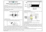
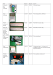
1. Components supplied with the Dessalator®: Version A3 Hull valve: It must be located the lowest possible in the boat, to the back for a motor yacht or in the centre near the keel for a sailing boat. The hull valve strainer filters out the larger particles at system entrance. Pre-filter: It must be located the nearest possible to the hull valve and be compulsory under the waterline. If not possible, there is a solution: Install a LP pump (optional). The pre-filter filters out solid particles down to 5 µm at the motor unit inlet. It is supplied with wrench. For automatic rinsing an electro-valve is mounted. Motor-Pump unit: It must be located compulsory under the waterline The motor-pump unit is comprised of the 12 or 24 V motor and a high pressure pump. Membrane unit:: The membrane unit includes 3 membranes 2521 assembled in a compact frame. According to the model, a fuse or a circuit breaker is supplied. Control panel: includes a HP gauge, a flowmeter, an on/off switch, a pressure adjustment knob, an operating time meter, 3 indicator lights. Pipes and hoses supplied by Dessalator®: - High pressure pipes pump/membranes and membranes/control panel (2 pipes and 4 special connectors) - Water production pipe membrane / control panel. Additional hardware needed for assembly: Miscellaneous screws (including Parker) Stainless jubilee clips 10 and 12 Assortment of plastic rings (tie wraps) Teflon tape or insulating water proof tape Silicon Rubson mastic, Sicaflex or equivalent Ribbed insulating pipe for cables and HP tubes Tricoflex hoses 10 and 12 Power cable: 50mm² for the 12V and 20mm² for the 24V Various tools (electric drill, saw, …) - Page 1 -