1
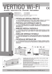
FEXL7105DG-02
ML7105 Hardware Design Manual
Bluetooth® Low Energy
Issue Date: December 8, 2014
ML7105 Hardware Design Manual
NOTES
No copying or reproduction of this document, in part or in whole, is permitted without the consent of LAPIS Semiconductor Co., Ltd.
The content specified herein is subject to change for improvement without notice.
Examples of application circuits, circuit constants and any other information contained herein illustrate the standard usage and
operations of the Products. The peripheral conditions must be taken into account when designing circuits for mass production.
Great care was taken in ensuring the accuracy of the information specified in this document. However, should you incur any damage
arising from any inaccuracy or misprint of such information, LAPIS Semiconductor shall bear no responsibility for such damage.
The technical information specified herein is intended only to show the typical functions of and examples of application circuits for the
Products. LAPIS Semiconductor does not grant you, explicitly or implicitly, any license to use or exercise intellectual property or other
rights held by LAPIS Semiconductor and other parties. LAPIS Semiconductor shall bear no responsibility whatsoever for any dispute
arising from the use of such technical information.
The Products specified in this document are intended to be used with general-use electronic equipment or devices (such as audio visual
equipment, office-automation equipment, communication devices, electronic appliances and amusement devices).
The Products specified in this document are not designed to be radiation tolerant.
While LAPIS Semiconductor always makes efforts to enhance the quality and reliability of its Products, a Product may fail or
malfunction for a variety of reasons.
Please be sure to implement in your equipment using the Products safety measures to guard against the possibility of physical injury, fire
or any other damage caused in the event of the failure of any Product, such as derating, redundancy, fire control and fail-safe designs.
LAPIS Semiconductor shall bear no responsibility whatsoever for your use of any Product outside of the prescribed scope or not in
accordance with the instruction manual.
The Products are not designed or manufactured to be used with any equipment, device or system which requires an extremely high level
of reliability the failure or malfunction of which may result in a direct threat to human life or create a risk of human injury (such as a
medical instrument, transportation equipment, aerospace machinery, nuclear-reactor controller, fuel-controller or other safety device).
LAPIS Semiconductor shall bear no responsibility in any way for use of any of the Products for the above special purposes. If a Product
is intended to be used for any such special purpose, please contact a ROHM sales representative before purchasing.
Copyright
2013 – 2014 LAPIS Semiconductor Co., Ltd.
2-4-8 Shinyokohama, Kouhoku-ku,
Yokohama 222-8575, Japan
http://www.lapis-semi.com/en/
FEXL7105DG-02
i
ML7105 Hardware Design Manual
Preface
This hardware design manual describes how to use the board and peripheral devices of ML7105, a
2.4 GHz-band radio communication LSI conforming to Bluetooth® Low Energy.
The following related manuals are available and should be referenced as needed:
■
■
■
■
ML7105-XXX Datasheet
Bluetooth Application Controller Interface (BACI) Command Manual
Application Developer’s Guide for ML7105
ML7105 User's Manual
•Bluetooth® is a registered trademark of Bluetooth SIG, Inc.
•All other company and product names are the trademarks or registered trademarks of the respective companies.
FEXL7105DG-02
ii
ML7105 Hardware Design Manual
Notation
Classification
Notation
Description
z Numeric value
0xnn
0bnnnn
Represents a hexadecimal number.
Represents a binary number.
z Address
0xnnnn_nnnn
Represents a hexadecimal number. (Indicates 0xnnnnnnnn)
z Unit
word, W
byte, B
Mega, M
Kilo, K (uppercase)
Kilo, k (lowercase)
Milli, m
Micro,μ
Nano, n
Second, s (lowercase)
1 word = 32 bits
1 byte = 8 bits
106
210=1024
103=1000
10-3
10-6
10-9
Second
z Term
"H" level
Signal level on the high voltage side; indicates the voltage level
of VIH and VOH as defined in electrical characteristics.
Signal level on the low voltage side; indicates the voltage level
of VIL and VOL as defined in electrical characteristics.
"L" level
z Register description
Read/write attribute: R indicates read-enabled; W indicates write-enabled.
MSB: Most significant bit in an 8-bit register (memory)
LSB: Least significant bit in an 8-bit register (memory)
FEXL7105DG-02
iii
ML7105 Hardware Design Manual
Table of Contents
NOTES ............................................................................................................................................................................i
Preface............................................................................................................................................................................ii
Notation ........................................................................................................................................................................iii
Table of Contents..........................................................................................................................................................iv
1. Using Bypass Capacitors .......................................................................................................................................... 1
2. Crystal Oscillator Circuit (26-MHz Master Clock) ................................................................................................. 3
2.1 Circuit Constant on External Board (as Reference Value)................................................................................ 3
2.2 Notes on Configuring a Crystal Oscillator Circuit ............................................................................................ 4
2.3 Frequency Adjustment Using XO Oscillation Frequency Adjustment Function ............................................. 4
2.3.1 RF Resistor 23 (XOTRIM2) ........................................................................................................................... 4
2.4 Activation time of a Crystal Oscillator Circuit .................................................................................................. 5
3. 32.768-kHz Low Power Clock ................................................................................................................................... 6
4. PLL Loop Filter Constant......................................................................................................................................... 7
5. RF Matching Constant Design ................................................................................................................................. 8
6. Selection of Parts..................................................................................................................................................... 10
Revision History .......................................................................................................................................................... 11
FEXL7105DG-02
iv
ML7105 Hardware Design Manual
1. Using Bypass Capacitors
The figure below shows the power supply system diagram of ML7105.
•ML7105 Power Supply System Diagram
External
power
VDDHV
supply
3.3V TYP
VDDBAT(9)
10uF
0.1uF
VDDIO(23)
REGOUT(8)
1.2V regulator
(Main)
VDDCORE(16)
0.1uF
VDDRF(2)
0.1uF
100pF
*[1]
18nH
Matching
Network
10ohm
SWOUT(3)
*[2]
VDDVCO(6)
10pF
*[3]
PMOS SW
SSM3J36MFV
GPIO3(29)
2.2 uF
REGC(12)
1.2V regulator
(LP)
10uF
*[4]
GND(GND at back surface)
Bypass capacitors shold be
placed just close to LSI
Figure 1.1 ML7105 Power Supply System Diagram
FEXL7105DG-02
1
ML7105 Hardware Design Manual
[*1] To supply power to the power amplifier in the LSI, it is necessary to apply DC voltage to the SWOUT(3) pin via an RF
choke (inductor).
[*2] As any power supply noise at the VDDVCO(6) pin will degrade the PLL output signal quality, a filter is inserted.
[*3] A PMOS SW is connected to the bypass capacitor 2.2 µF of the VDDVCO(6) pin and controlled by the GPIO3(29) pin.
This prevents the electrical charge accumulated in the capacitor from being discharged and reduces the current consumption.
The GPIO3(29) pin operates in accordance with the operation mode and connects/disconnects the capacitor according to the
ON/OFF state of the 1.2 V regulator to reduce the activation time.
[*4] In the LSI, the analog GNDs and digital GNDs are connected to the GND at back surface.
Note the followings when placing bypass capacitors:
1.
2.
3.
4.
5.
6.
7.
8.
The VDD and GND traces should be wider than the other signal line traces to reduce the trace resistance.
Bypass capacitors should be placed just close to LSI pins.
A bypass capacitor with smaller capacitance needs to be placed more close to an LSI pin.
Input/output pins should have a capacitance of about 10 µF to ensure the stability of the 1.2 V regulator (LP).
For the VDDBAT(9)/VDDIO(23) pins, LAPIS recommends a 10 µF tantalum capacitor connected in parallel with a
0.1 µF laminated ceramic capacitor. When you connect the VDDBAT(9) pin to the VDDIO(23) pin, the total
capacitance should be designed to be about 10 µF.
The total capacitance connected to the REGOUT(8) pin should be 0.3 µF or less. If a capacitance of µF order is
connected, the current consumption may increase and the activation time may become longer to charge the capacitance.
In that case, use MOS_SW as for the VDDVCO(6) pin to prevent the electrical charge from being discharged.
In general, ceramic capacitors have specific temperature and voltage characteristics. Select the best capacitor for the
operating voltage and temperature of your specific application. If you use high-dielectric capacitors (class II), LAPIS
recommends B characteristics.
This LSI has the low power consumption mode (Deep Sleep state). In this mode, the current consumption of the LSI is
about 0.7 µA and the leakage current from the external capacitor cannot be ignored. To achieve the design with low
power consumption, LAPIS recommends to select parts with very low leakage current, considering the leakage current
from the used capacitor.
FEXL7105DG-02
2
ML7105 Hardware Design Manual
2. Crystal Oscillator Circuit (26-MHz Master Clock)
The figure below shows a configuration example when a crystal oscillator is used. Capacitors for the XOP(13) and
XON(14) pins are required so that the crystal oscillator circuit provides stable oscillation of 26 MHz. To determine the
constants, LAPIS recommends evaluating the overall capacitance of the board to be used, including the parasitic
capacitance.
The considerations should include excitation level, oscillation margin ratio, frequency deviation, and activation time of
oscillator circuit.
XOP(13)
XON(14)
R1
C1
X'tal
26MHz
C2
Figure 2.1 Example of ML7105 26-MHz Crystal Oscillator Circuit Configuration
2.1 Circuit Constant on External Board (as Reference Value)
LAPIS recommends to ask your crystal oscillator manufacturer to get the matching property data for your board.
The matching constants for our evaluation board are shown below.
Table 2.1.1 Matching Constants When Using Crystal Oscillator by Seiko Epson Corp.
Frequency
Equivalent
Load
Oscillator
Constant (as reference value)
Operating condition
model
name
(MHz)
series
resistance
max (Ω)
capacitance
(pF)
R1(Ω)
C1(pF)
C2(pF)
Power supply
voltage range
VDDBAT (V)
Temperature
range
(°C)
FA20H
26.00
60
8.0
0
10
10
1.6 to 3.6
-20 to 70
Oscillator
model
name
Frequency
(MHz)
Equivalent
series
resistance
max (Ω)
Load
capacitance
(pF)
R1(Ω)
C1(pF)
C2(pF)
Power supply
voltage range
VDDBAT (V)
Temperature
range
(°C)
FA-128
26.00
60
8.0
0
7
8
1.6 to 3.6
-20 to 70
Constant (as reference value)
Table 2.1.2 Matching Constants When Using Crystal Oscillator by Daishinku Corp.
Load
Frequency
Equivalent
Oscillator
Constant (as reference value)
Operating condition
Operating condition
model
name
(MHz)
series
resistance
max (Ω)
capacitance
(pF)
R1(Ω)
C1(pF)
C2(pF)
Power supply
voltage range
VDDBAT (V)
Temperature
range
(°C)
DSX221G
26.00
60
8.0
0
10
12
1.6 to 3.6
-20 to 70
FEXL7105DG-02
3
ML7105 Hardware Design Manual
Table 2.1.3 Matching Constants When Using Crystal Oscillator by Nihon Dempa Kogyo Co., Ltd.
Load
Frequency
Equivalent
Oscillator
Constant (as reference value)
Operating condition
model
name
(MHz)
series
resistance
max ( )
capacitance
(pF)
R1(Ω)
C1(pF)
C2(pF)
Power supply
voltage range
VDDBAT (V)
Temperature
range
(°C)
NX2520SA
26.00
60
6.0
0
5
6
1.6 to 3.6
-20 to 70
[Note]
The above circuit constants are values evaluated on a specific sample and board and provided for your information, and
thus its content is not guaranteed.
2.2 Notes on Configuring a Crystal Oscillator Circuit
Note the followings when configuring a crystal oscillator circuit:
1. Be sure to set the values of the peripherals (C1, C2, and R1) according to the specifications of the crystal oscillator to
be used.
2. Place the peripherals (C1, C2, and R1) just close to the XOP(13) and XON(14) pins to reduce the parasitic capacitance
of the board for stable oscillation operation.
3. For the 26-MHz master clock, ensure accuracy[*1] under the recommended operating conditions described in the
specifications including temperature variations, power supply voltage variations, and aging changes.
4. Be sure the crystal oscillator circuit does not cross other signal lines.
5. Do not wire signal lines that flow large currents near the circuit.
6. For the oscillator circuit capacitors, make sure the potential of the ground points is always equal to that of the GND.
Do not connect the capacitors to GNDs where large currents flow.
7. Do not take oscillation signals from the oscillator circuit.
[*1] When the above accuracy is not satisfied, fine tuning can be performed by using the XO oscillation frequency
adjustment function described in section 2.3.
2.3 Frequency Adjustment Using XO Oscillation Frequency Adjustment Function
26 MHz of the master clock can be fine tuned by the XO oscillation frequency adjustment function using the RF registers
described below. The RF registers can be read or written by using the BACI Commands or HCI Vendor Commands.
<BACI Command>
• Write_RF_Reg
• Read_RF_Reg
<HCI Vendor Command>
• HCI_VENDOR_RF_RADIO_REG_WRITE
• HCI_VENDOR_RF_RADIO_REG_READ
2.3.1 RF Resistor 23 (XOTRIM2)
RF
Register23
Initial Value
15
14
-*
-*
0
0
13
12
11
10
9
8
XO_FFIN
0
0
1
0
Access
R/W R/W R/W R/W R/W R/W
Address: 0x17
Initial Value: 0x0800
[Note]*: Do not change the initial value.
7
6
5
4
3
2
1
0
-*
-*
-*
-*
-*
-*
-*
-*
0
0
0
0
0
0
0
0
0
0
R/W
R/W
R/W
R/W
R/W
R/W
R/W
R/W
R/W
R/W
[Description of Bits]
Field
XO_FFIN
FEXL7105DG-02
bit
13:8
Description
Fine-tunes the XO oscillation frequency.
00h: Highest frequency setting (fast), 3Fh: Lowest frequency setting (slow)
4
ML7105 Hardware Design Manual
Adjustment example:
Step1 Set the 2440-MHz continuous Tx operation state[*1].
Step2 Measure the RF transmit frequency with a frequency counter or spectrum analyzer.
Step3 Use RF Resistor 23 described above to adjust the RF transmit frequency so that its value is within the
recommended operating range described in the specifications.
[*1] For setting the continuous Tx operation state, refer to the section "Continuous transmission test" in "7. RF Test Mode & Direct Test
Mode" of the "ML7105 User's Manual".
The value of RF Resistor 23 is reset to the initial value (0x0800) each time ML7105 is reset. If you have adjusted the XO
oscillation frequency by using the XO oscillation frequency adjustment function, make sure the adjustment value is written
to RF Resistor 23 at each reset.
2.4 Activation time of a Crystal Oscillator Circuit
This LSI has the low power consumption mode (Deep Sleep state). In this mode, 1.2 V regulator (Main) and 26MHz
Crystal Oscillator Circuit shut down. Make the 26MHz Crystal Oscillator activation time less than 1ms at the time of return
from the low power consumption. If the activation time is long, ML7105 can’t keep the communication state for the
communication timing mismatching.
To determine the constants, LAPIS recommends evaluating the activation time including the parasitic capacitance.
The method of evaluating the activation time:
Step1 Monitor the REGOUT(8) and XON(14) pins with oscilloscope. At monitoring the XON(14) pin, use such as FET
probe for decrease the probe parasitic capacitance.
Step2 The voltage of the REGOUT(8) pin rise at the same time of return from the low power consumption. Measure the
time till the amplitude of XON(14) pin become around 600mVpp from the voltage of REGOUT(8) pin rise.
The activation time for our evaluation board are shown below. (Using FA20H)
The activation time contains 1.2 V regulator (Main) activation and Crystal Oscillator activation. The target activation time
of 1.2 V regulator (Main) is 200us Max. And Crystal Oscillator is 800us Max. Make less than 1ms for the total activation
time.
Return from the low power consumption
REGOUT (8)
(Trigger)
Around 600mVpp
XON (14)
(FET probe 3pF)
Total Activation Time (728us)
(1.2V regulator (Main) + Crystal Oscillator activation time)
[Note]
The above circuit constants are values evaluated on a specific sample and board and provided for your information, and
thus its content is not guaranteed.
FEXL7105DG-02
5
ML7105 Hardware Design Manual
3. 32.768-kHz Low Power Clock
ML7105 has the external input mode for the Low power clock.
The figure below shows a circuit configuration example when using the external input mode. When using the external
input mode, input a clock which satisfies the following characteristics from the LPCLKIN(11) pin:
・
・
・
Frequency: 32.768kHz ±250ppm
Input voltage VIH: 1 to VDDIO[V], VIL: 0 to 0.3[V]
Duty: 50% ±20%
To use the external input mode, Tx and Rx characteristics may be influenced by the clock. LAPIS recommends to put in
damping resistor at LPCLKIN(11) pin when .using the external input mode.
To determine the resistor constant, LAPIS recommends evaluating the Tx and Rx characteristics.
Figure 3.1 Example of ML7105 Circuit Configuration in 32.768-kHz External Input Mode
FEXL7105DG-02
6
ML7105 Hardware Design Manual
4. PLL Loop Filter Constant
The figure below shows the PLL loop filter circuit. Use the constants for parts shown in the figure below to achieve good
phase noise characteristics. Select parts with good temperature characteristics.
Place the loop filter parts (C1, R1 and C2) just close to the PLLLPF(7) pin to avoid noise contamination. Do not place
traces causing noise such as reference clock traces around this pin.
PLLLPF(7)
C1
680pF
R1
1.2kΩ
C2
3300pF
Figure 4.1 ML7105 PLL Loop Filter Configuration
FEXL7105DG-02
7
ML7105 Hardware Design Manual
5. RF Matching Constant Design
The figure below shows a standard RF matching circuit configuration.
The REGOUT(8) pin outputs 1.2 V. For PA power supply, the output from the REGOUT(8) pin is applied to the
SWOUT(3) pin via the choke coil L1. L3 and C12 constitute a double wave trap. C13 is a capacitor for decoupling. For the
VDDRF(2) pin, place 0.1µF and 100pF as bypass capacitors just close to the LSI.
C9 and C10 are used when the matching needs to be changed between RX and TX. The SWRX(4) pin (during Rx) or the
SWTX(5) pin (during Tx) is connected to GND by using the SW within the LSI. With the matching of our evaluation
board, these are NM (No Mount).
1.2V regulator
(Main)
REGOUT(8)
VDDRF(2)
ANTENNA
0.1uF
L13 10pF
LNA
100pF
L2 2.5nH
L1
18nH
SWOUT(3)
L3
1nH
C12
0.5pF
C11
1.8pF
C9 NM
SWRX(4)
PA
RXON
C10 NM
SWTX(5)
The blue line indicates 50Ω line
TXON
Z0=50Ω (f=2440MHz)
GND(GND at back surface)
Figure 5.1 Example of ML7105 RF Matching Circuit Configuration
In the above circuit diagram, the matching is adjusted by adjusting L2 and C11. The matching is performed so that the
input impedance from the antenna is near 50Ω and VSWR is 2 or less during a continuous Rx operation [*1]. The
frequency band to be adjusted is 2402 to 2480 MHz. At this time, if C11 is too large, PA becomes inefficient. Adjust C11
using 2 pF or less as a guide.
After the adjustment, perform a transmission test to make sure that the transmitter power is not reduced.
[*1] For setting the continuous Rx operation state, refer to the section "Continuous reception test" in "7. RF Test Mode & Direct Test
Mode" of the "ML7105 User's Manual".
FEXL7105DG-02
8
ML7105 Hardware Design Manual
The figure below shows the input impedance characteristics (S11) during a continuous Rx operation of our evaluation
board.
S11
Log
S11
Phase
S11
VSWR
Figure 5.2 ML7105 RF Input Impedance Characteristics (During Continuous Rx Operation)
2402MHz[1], 2440MHz[2], 2480MHz[3]
[Note]
The above measurement result is a value measured for a specific sample and provided for your information, and thus its
content is not guaranteed.
FEXL7105DG-02
9
ML7105 Hardware Design Manual
6. Selection of Parts
1.
Antenna
LAPIS recommends using an antenna with the specifications shown in Table 6.1.
Select an antenna with the best directivity characteristics for your specific operating, environmental and installation
conditions. Since antennas are affected by installation conditions such as GND, external factors should always be
taken into account.
LAPIS recommends consulting the manufacturer of the selected antenna for installation details in relation to various
factors, including the shape and stray capacitance of the board to be used.
Frequency band
In-band VSWR
Nominal impedance
Table 6.1 Antenna
2.4-GHz band
2.0MAX
50Ω
2.
External regulator
Use a regulator that is characterized by high accuracy, low noise, and high ripple elimination and whose operating
temperature is appropriate for your purpose.
If the traces to the power supply input pins and GND pins have too high impedances, the resulting noise will cause
return currents that make operations unstable. Therefore, provide sufficiently low impedances for these traces.
3.
Inductors
Use high Q inductors. LAPIS recommends LQW15A series by Murata Manufacturing (±5% deviation, Q>20).
4.
Capacitors
Use temperature compensation type capacitors. LAPIS recommends capacitors with CH characteristics.
LAPIS recommends low-dielectric capacitors (class I) of 0±60 ppm/°C or less for areas that affect radio
communication characteristics.
5.
Resistors
Use resistors which have small resistance to the temperature change.
FEXL7105DG-02
10
ML7105 Hardware Design Manual
Revision History
Document No.
FEXL7105DG-01
FEXL7105DG-02
Issue date
2013.04.25
Page
Before
After
–
–
Cover
Cover
6
6
2014.12.8
10
FEXL7105DG-02
10
NOTE
st
Final 1 edition
Changed LAPIS logotype
Added damping resistor at 32.768kHz external input
mode
Delete about the Low power clock built-in crystal
oscillator input circuit
Figure 5.1 Modified instances name
11