1
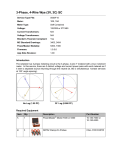
ALC-1 ALC Inhibit User Manual
Description
The Array Solutions ALC-1 Transmitter Inhibit controller interfaces between your
amplifier’s ALC output, your PowerMaster PTT connections, and your transceiver’s
ALC input to provide fast, rapid protection of your transceiver and amplifier when a
sudden high SWR event occurs.
The Array Solutions PowerMaster provides a PTT feature which can be used to unkey
your amplifier when an SWR reading above a user-selectable pre-set limit occurs.
However, when this occurs your transceiver’s output can be hot-switched since the
amplifier is being unkeyed while your transceiver is still putting out full power. Further,
some amplifiers are designed such that they do NOT unkey as long as RF is present so as
to eliminate the possibility of amplifier hot-switching until the RF input has completely
decayed to zero. So these amplifiers can be subjected to a high SWR which could
possibly damage them.
The Array Solutions ALC-1 Transmit Inhibit controller eliminates these potential hotswitching or high-SWR operating problems by instantly applying a cut-off ALC voltage
to your transceiver when the high SWR event occurs. This turns down your transmitter
RF power faster than the amplifier RF relays can operate, ensuring that no hot-switching
can occur.
Connections
Simply connect the two RCA pendant cables of the ALC-1 to the PTT jacks on the back
of the PowerMaster. Either cable can be connected to either PTT jack. Connect the
amplifier’s ALC output to the AMP ALC jack on the ALC-1, and connect the TX ALC
output to your transceiver’s ALC input via an RCA cable. All connections are shown
below:
Transceiver
Amplifier
ALC IN
ALC OUT
PowerMaster
PTT
PTT
PTT
PTT
Antenna
System
ALC-1
AMP ALC
TX ALC
ALC-1 Connection Diagram
Set-Up
1) Ignore Step 2 if your amplifier does NOT provide an ALC connection or you have
elected to not use ALC feedback from your amplifier. Also, no ALC connection to
the amplifier will be required in this case.
2) With the PowerMaster turned OFF, adjust your amplifier/transceiver ALC as
described in your amplifier’s operation manual.
3) Set the ALC SET control on the ALC-1 fully counter-clockwise.
4) Turn ON your PowerMaster and select the “VSWR Alarm Menu”. Set the VSWR
alarm to the desired value at which you want to protect your transceiver and
amplifier.
5) Select the PowerMaster “Alarm Polarity Menu” and set it for “Alarm Opens Relay”.
6) With your amplifier bypassed, key your transceiver to full output and adjust the ALC
SET control on the ALC-1 for zero transmitter output power.
7) On the PowerMaster “Alarm Polarity Menu”, set it for “Alarm Closes Relay”.
You can now operate normally. Whenever a high SWR condition occurs, the ALC-1 will
operate and reduce your transceiver’s RF output to zero.
ALC-1 Maintenance.
The ALC-1 contains an internal 9VDC battery. This battery is only used when a high
SWR condition occurs, therefore the battery life-time will equal the battery shelf life.
You will probably never need to replace this battery.