1
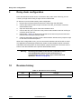
UM1654 User manual SPIN family evaluation software Introduction This user manual describes how to use the SPIN family evaluation software. The SPIN family evaluation software allows STMicroelectronics® customers to easily evaluate functionalities and performances of the devices of dSPIN™ and cSPIN™ families. This software is designed to work with the IBU universal interface demonstration board (STEVAL-PCC009V2). Before starting, please take some time to visit the STMicroelectronics web site. There updated datasheets, application notes and the latest version of the software can be found. See www.st.com/dspin and www.st.com/cspin. September 2013 DocID025040 Rev 1 1/39 www.st.com Contents UM1654 Contents 1 Installation . . . . . . . . . . . . . . . . . . . . . . . . . . . . . . . . . . . . . . . . . . . . . . . . . 6 2 Quick start guide . . . . . . . . . . . . . . . . . . . . . . . . . . . . . . . . . . . . . . . . . . . . 7 3 2.1 STEVAL-PCC009V2 firmware upgrade . . . . . . . . . . . . . . . . . . . . . . . . . . . 8 2.2 Drivers installation (old firmware revision only) . . . . . . . . . . . . . . . . . . . . . 8 SPINFamily evaluation software . . . . . . . . . . . . . . . . . . . . . . . . . . . . . . . 9 3.1 Menu and toolbar . . . . . . . . . . . . . . . . . . . . . . . . . . . . . . . . . . . . . . . . . . . 10 3.2 Command section . . . . . . . . . . . . . . . . . . . . . . . . . . . . . . . . . . . . . . . . . . 10 3.3 3.4 4 2/39 3.2.1 “Positioning” tab . . . . . . . . . . . . . . . . . . . . . . . . . . . . . . . . . . . . . . . . . . . 10 3.2.2 “Speed” tab . . . . . . . . . . . . . . . . . . . . . . . . . . . . . . . . . . . . . . . . . . . . . . 11 3.2.3 “Advanced” tab . . . . . . . . . . . . . . . . . . . . . . . . . . . . . . . . . . . . . . . . . . . 12 3.2.4 Stop buttons . . . . . . . . . . . . . . . . . . . . . . . . . . . . . . . . . . . . . . . . . . . . . . 13 Status display . . . . . . . . . . . . . . . . . . . . . . . . . . . . . . . . . . . . . . . . . . . . . . 13 3.3.1 HiZ LED . . . . . . . . . . . . . . . . . . . . . . . . . . . . . . . . . . . . . . . . . . . . . . . . . 14 3.3.2 UVLO LED . . . . . . . . . . . . . . . . . . . . . . . . . . . . . . . . . . . . . . . . . . . . . . . 15 3.3.3 OCD LED . . . . . . . . . . . . . . . . . . . . . . . . . . . . . . . . . . . . . . . . . . . . . . . . 15 3.3.4 Thermal status LED . . . . . . . . . . . . . . . . . . . . . . . . . . . . . . . . . . . . . . . . 16 3.3.5 Stall LEDs . . . . . . . . . . . . . . . . . . . . . . . . . . . . . . . . . . . . . . . . . . . . . . . 16 3.3.6 BUSY LED . . . . . . . . . . . . . . . . . . . . . . . . . . . . . . . . . . . . . . . . . . . . . . . 17 3.3.7 Motor status indicator . . . . . . . . . . . . . . . . . . . . . . . . . . . . . . . . . . . . . . 18 3.3.8 Switch event and switch status LEDs . . . . . . . . . . . . . . . . . . . . . . . . . . 19 3.3.9 StepClock mode LED . . . . . . . . . . . . . . . . . . . . . . . . . . . . . . . . . . . . . . . 20 3.3.10 Command error LED . . . . . . . . . . . . . . . . . . . . . . . . . . . . . . . . . . . . . . . 20 Opening and saving multiple device configurations . . . . . . . . . . . . . . . . . 21 Register map . . . . . . . . . . . . . . . . . . . . . . . . . . . . . . . . . . . . . . . . . . . . . . 23 4.1 Writing registers . . . . . . . . . . . . . . . . . . . . . . . . . . . . . . . . . . . . . . . . . . . . 24 4.2 Reading registers . . . . . . . . . . . . . . . . . . . . . . . . . . . . . . . . . . . . . . . . . . . 25 4.3 Loading and saving configurations . . . . . . . . . . . . . . . . . . . . . . . . . . . . . . 25 DocID025040 Rev 1 UM1654 5 6 Contents Device configuration tool . . . . . . . . . . . . . . . . . . . . . . . . . . . . . . . . . . . . 26 5.1 “Speed Profile” tab . . . . . . . . . . . . . . . . . . . . . . . . . . . . . . . . . . . . . . . . . . 27 5.2 “Phase current control” tab for the voltage mode devices . . . . . . . . . . . . 28 5.3 “Phase current control” tab for the current mode devices . . . . . . . . . . . . 29 5.4 “Gate driving” tab (cSPIN™ family only) . . . . . . . . . . . . . . . . . . . . . . . . . 30 5.5 “Others” tab . . . . . . . . . . . . . . . . . . . . . . . . . . . . . . . . . . . . . . . . . . . . . . . 31 5.6 Load and save configuration . . . . . . . . . . . . . . . . . . . . . . . . . . . . . . . . . . 32 BEMF compensation tool . . . . . . . . . . . . . . . . . . . . . . . . . . . . . . . . . . . . 33 Saving and loading application and motor parameters. . . . . . . . . . . . . . . . . . . . . 34 7 Scripting environment . . . . . . . . . . . . . . . . . . . . . . . . . . . . . . . . . . . . . . 35 7.1 Writing scripts . . . . . . . . . . . . . . . . . . . . . . . . . . . . . . . . . . . . . . . . . . . . . . 36 7.2 Script execution . . . . . . . . . . . . . . . . . . . . . . . . . . . . . . . . . . . . . . . . . . . . 36 8 Options . . . . . . . . . . . . . . . . . . . . . . . . . . . . . . . . . . . . . . . . . . . . . . . . . . . 37 9 Daisy chain configuration . . . . . . . . . . . . . . . . . . . . . . . . . . . . . . . . . . . 38 10 Revision history . . . . . . . . . . . . . . . . . . . . . . . . . . . . . . . . . . . . . . . . . . . 38 DocID025040 Rev 1 3/39 39 List of tables UM1654 List of tables Table 1. Table 2. Table 3. Table 4. Table 5. Table 6. Table 7. Table 8. Table 9. Table 10. Table 11. Table 12. Table 13. 4/39 Menu items and toolbar buttons of the main form . . . . . . . . . . . . . . . . . . . . . . . . . . . . . . . 10 HiZ LED indicator . . . . . . . . . . . . . . . . . . . . . . . . . . . . . . . . . . . . . . . . . . . . . . . . . . . . . . . . 14 UVLO LED indicator . . . . . . . . . . . . . . . . . . . . . . . . . . . . . . . . . . . . . . . . . . . . . . . . . . . . . . 15 OCD LED indicator . . . . . . . . . . . . . . . . . . . . . . . . . . . . . . . . . . . . . . . . . . . . . . . . . . . . . . . 15 Thermal status LED indicator . . . . . . . . . . . . . . . . . . . . . . . . . . . . . . . . . . . . . . . . . . . . . . . 16 Stall LED indicators . . . . . . . . . . . . . . . . . . . . . . . . . . . . . . . . . . . . . . . . . . . . . . . . . . . . . . 17 Busy LED indicator . . . . . . . . . . . . . . . . . . . . . . . . . . . . . . . . . . . . . . . . . . . . . . . . . . . . . . . 17 Motor status indicator . . . . . . . . . . . . . . . . . . . . . . . . . . . . . . . . . . . . . . . . . . . . . . . . . . . . . 18 SW event LED indicator . . . . . . . . . . . . . . . . . . . . . . . . . . . . . . . . . . . . . . . . . . . . . . . . . . . 19 SW status LED indicator . . . . . . . . . . . . . . . . . . . . . . . . . . . . . . . . . . . . . . . . . . . . . . . . . . . 19 StepClock mode LED indicator . . . . . . . . . . . . . . . . . . . . . . . . . . . . . . . . . . . . . . . . . . . . . . 20 Command error LED indicator . . . . . . . . . . . . . . . . . . . . . . . . . . . . . . . . . . . . . . . . . . . . . . 20 Document revision history . . . . . . . . . . . . . . . . . . . . . . . . . . . . . . . . . . . . . . . . . . . . . . . . . 38 DocID025040 Rev 1 UM1654 List of figures List of figures Figure 1. Figure 2. Figure 3. Figure 4. Figure 5. Figure 6. Figure 7. Figure 8. Figure 9. Figure 10. Figure 11. Figure 12. Figure 13. Figure 14. Figure 15. Figure 16. Figure 17. Figure 18. Device selection dialog . . . . . . . . . . . . . . . . . . . . . . . . . . . . . . . . . . . . . . . . . . . . . . . . . . . . . 7 Main form . . . . . . . . . . . . . . . . . . . . . . . . . . . . . . . . . . . . . . . . . . . . . . . . . . . . . . . . . . . . . . . 9 Positioning tab in command section . . . . . . . . . . . . . . . . . . . . . . . . . . . . . . . . . . . . . . . . . . 11 Speed tab in command section . . . . . . . . . . . . . . . . . . . . . . . . . . . . . . . . . . . . . . . . . . . . . 12 Advanced tab in command section . . . . . . . . . . . . . . . . . . . . . . . . . . . . . . . . . . . . . . . . . . . 12 Stop buttons in command section. . . . . . . . . . . . . . . . . . . . . . . . . . . . . . . . . . . . . . . . . . . . 13 Status display . . . . . . . . . . . . . . . . . . . . . . . . . . . . . . . . . . . . . . . . . . . . . . . . . . . . . . . . . . . 14 Open configuration group form . . . . . . . . . . . . . . . . . . . . . . . . . . . . . . . . . . . . . . . . . . . . . . 21 Save configuration group form . . . . . . . . . . . . . . . . . . . . . . . . . . . . . . . . . . . . . . . . . . . . . . 22 Register map form . . . . . . . . . . . . . . . . . . . . . . . . . . . . . . . . . . . . . . . . . . . . . . . . . . . . . . . 23 Speed profile tab in device configuration form . . . . . . . . . . . . . . . . . . . . . . . . . . . . . . . . . . 27 Voltage mode driving tab in device configuration form . . . . . . . . . . . . . . . . . . . . . . . . . . . . 28 Advanced current control driving tab in device configuration form . . . . . . . . . . . . . . . . . . . 29 Gate driving tab in device configuration form . . . . . . . . . . . . . . . . . . . . . . . . . . . . . . . . . . . 30 “Others” tab in device configuration form . . . . . . . . . . . . . . . . . . . . . . . . . . . . . . . . . . . . . . 31 BEMF compensation form . . . . . . . . . . . . . . . . . . . . . . . . . . . . . . . . . . . . . . . . . . . . . . . . . 33 Scripting environment form . . . . . . . . . . . . . . . . . . . . . . . . . . . . . . . . . . . . . . . . . . . . . . . . . 35 Options dialog . . . . . . . . . . . . . . . . . . . . . . . . . . . . . . . . . . . . . . . . . . . . . . . . . . . . . . . . . . . 37 DocID025040 Rev 1 5/39 39 Installation 1 UM1654 Installation The software requirements are the following: Computer mounting Windows 7 OS(a). A free USB port. IBU universal interface board (STEVAL-PCC009V2). One or more demonstration boards compatible with the software environment (check on the STEVAL-PCC009V2 board documentation). To install the software: 1. Unzip the archive content 2. Start software installation using “SPINFamily Setup.msi” file 3. Follow the guided installation instructions A link to the application is created into the START menu: (All Programs/STMicroelectronics/SPINFamily Evaluation Tool). a. Some old version of the STEVAL-PCC009V2 firmware works on Windows XP OS only. In this case, please refer to Section 2.1 for the firmware upgrade instructions. 6/39 DocID025040 Rev 1 UM1654 2 Quick start guide Quick start guide Before start working with the evaluation software the firmware mounted on the IBU universal interface board must be checked in order to verify if it is compatible with the application and eventually update it to the last revision. See Section 2.1 for the details. The software is designed to work in demonstration mode, so all functionalities can be explored even if no demonstration boards are present (neither the STEVAL-PCC009V2 nor the demonstration boards of the devices are required in this case). 1. Start the “SPINFamily Evaluation Tool” (by default it is in Start menu > All programs > STMicroelectronics > SPINFamily Evaluation Tool). 2. When the application is started the device selection dialog of Figure 1 is shown. Figure 1. Device selection dialog 3. Click on the target device. 4. Plug the STEVAL-PCC009V2 communication board to a free USB port (the cable is not included). 5. Wait a few seconds for board initialization. 6. Connect the SPI_IN connector (black) of the demonstration board to the 10-pin connector of the IBU universal interface board using the provided cable. For connecting more devices to the same board, please consult the daisy chain connection paragraph (Section 3). 7. Power up the demonstration boards. 8. Click on the button with the USB symbol to connect the IBU universal interface board to the PC and initialize the evaluation environment. The application automatically identifies the number of demonstration boards connected. 9. The evaluation environment is ready. DocID025040 Rev 1 7/39 39 Quick start guide 2.1 UM1654 STEVAL-PCC009V2 firmware upgrade A tool to update the firmware named “IBUUI updater” is installed with the application.This tool can be also used to check if the firmware mounted on the board is compatible with the evaluation software. 2.2 1. Start the IBUUI updater tool (by default it is in Start menu > All programs > STMicroelectronics > SPINFamily Evaluation Tool). If the communication board mounts an early version of the firmware, the first time the communication board is connected to the PC, driver installation procedure could be required (see Section 2.2). 2. Click on the “start” button. 3. Follow the guided procedure. Drivers installation (old firmware revision only) This procedure is used to install STEVAL-PCC009V2 drivers which are required by the early version of the firmware. This operation is requested only the first time the board is connected to the PC; if they are already installed this procedure can be skipped. 8/39 1. Connect the board to the PC through a USB cable. 2. System should start the assisted driver installation procedure. 3. Chose “No, not this time” option and click “Next”. 4. Chose to install the device driver automatically (recommended). 5. If the drivers are not found: a) Chose to install the device driver from a specific location. b) Select the first option and check “Include this location in the search”. c) Select the driver path clicking on the “Browse” button: drivers are installed into the “Updater\Drivers\WinXP” subfolder in the SPINFamily Evaluation Tool folder (by default it is Program Files\STMicroelectronics\SPINFamily Evaluation Tool\ Updater\Drivers\WinXP). 6. When the driver certification warning is shown click on the “Continue Anyway” option. 7. Driver installation is completed and the communication board is now operative. DocID025040 Rev 1 UM1654 3 SPINFamily evaluation software SPINFamily evaluation software When the application starts the form is shown in Figure 2. The form is divided into two main sections: the command section, on the top, that collects all the device commands and allows reading/writing the absolute position and the speed registers. The device status display, on the bottom, that shows the last information collected from the status register. Between the command section and the toolbar the device selection and reset buttons can be found. When more devices are driven in daisy chain configuration, these buttons can be used to select the device to control. All the commands are sent only to the selected device and the application can drive only one device at a time. See Section 9 on page 38 for further details. The “RESET” button forces low the STBY/RESET line of the communication board after a warning message. Clicking on the button again releases the STBY/RESET line. The menu and toolbar provide access to extra tools and allow opening/saving the device configuration. The status bar on the bottom side of the form shows the current board status and the SPI communication speed. On the right corner the status of BUSY and FLAG lines can be found: red text indicates that the respective line is low. Figure 2. Main form DocID025040 Rev 1 9/39 39 SPINFamily evaluation software 3.1 UM1654 Menu and toolbar Table 1 lists the content of the menu of the main form and the toolbar buttons with a brief description of each item. Table 1. Menu items and toolbar buttons of the main form Menu item Toolbar button Description File\Open Load a group of configuration files and write them into the devices. File\Save Save the setup of the devices in a group of configuration files. File\Exit - Close the application. Tools\Connect board Connect and disconnect the IBU universal interface board from the PC. Tools\Register map Open the “Register map” tool (see Section 4 on page 23). Tools\Device configuration Open the “Device configuration” tool (see Section 5 on page 26). Tools\BEMF compensation Open the BEMF compensation evaluator tool for the voltage mode driving (see Section 6 on page 33). Tools\Script editor Open the scripting environment (see Section 7 on page 35). Tools\Options - Open the application option dialog (see Section 8 on page 37). ?\Help - Open the help file. ?\About - Show detailed information about the software. ?\Web - Open the STMicroelectronics web page. 3.2 Command section Command section collects all commands and allows reading and writing ABS_POS, MARK and SPEED registers. For a detailed description of the command set of the device, please refer to the DS6582, DS8858, DS9080 and DS9306 device datasheets and AN4241, AN4290 application notes on st.com. 3.2.1 “Positioning” tab The positioning tab collects all the motion commands allowing the device to reach target positions. 10/39 DocID025040 Rev 1 UM1654 SPINFamily evaluation software Figure 3. Positioning tab in command section GoTo and GoTo_DIR commands can be sent to the selected device clicking on the “GoTo” button. If the “AUTO” button is selected, the GoTo command is sent and the motion direction is selected by the device using the minimum path algorithm. “FW” and “BW” buttons force a forward/backward direction sending a GoTo_DIR command. Position argument is set by a numeric box next to the button and can vary within -2097152 and 2097151 (the absolute position is expressed in a 2 s complement format). The target position can be written directly or it can be changed using up and down arrows positioned on the right side of the box. GoTo or GoTo_DIR command can also be sent pushing the return key in this numeric box. Clicking on the “Move” button a Move command is sent to the current active device. The motion direction is selected through “FW” (forward) and “BW” (backward) buttons and the number of steps is set by a numeric box next to the button. This value goes from 0 to 4194303. The value can be directly written within the box or it can be adjusted using up and down arrows. The Move command can also be sent pushing the return key in the numeric box. The “Positioning” tab also gives quick access to the ABS_POS register. Clicking on the “RD” button the current ABS_POS value of the selected device is read and it is returned into the numeric box. If “Autorefresh” is checked, the absolute position is automatically updated at the selected polling rate. Clicking the “WR” button the ABS_POS register is written, the desired value must be set into the numeric box (-2097152 to 2097151). The same operation can be performed pushing the return key in the numeric box. The “HOME” button resets ABS_POS register to home position (zero). 3.2.2 “Speed” tab The speed tab collects all the motion commands allowing the device to reach a target speed. DocID025040 Rev 1 11/39 39 SPINFamily evaluation software UM1654 Figure 4. Speed tab in command section Clicking on the “Run” button a Run command is sent to the current active device. Motion direction is selected through “FW” (forward) and “BW” (backward) buttons and target speed is set by a numeric box next to the button. This value ranges from 0 to 15624.985 (expressed in step/s) and can be directly written in the box or it can be changed using the up and down arrows. Pushing the return key in the number box sends a Run command also. In the “Speed” tab is also allowed reading the current SPEED register value by clicking on the “RD” button. If “Autorefresh” is checked, the speed value is automatically updated at the selected polling rate. 3.2.3 “Advanced” tab Figure 5. Advanced tab in command section The “GoMark” and “GoHome” buttons in the “Advanced” tab send the respective command to the selected device. In this tab quick access to MARK register is also provided. Clicking on the “RD” button or the current MARK value of the selected device is read and it is returned into the numeric box. The register can be written setting the desired value into the numeric box (-2097152 to 2097151) and pushing the return key or clicking on the “WR” button. 12/39 DocID025040 Rev 1 UM1654 SPINFamily evaluation software The “GoUntil” button sends the respective command using the parameters indicated by the adjacent controls: The numeric box defines the target speed (expressed in step/s). Its value ranges from 0 to 15624.985 and can be set directly or by means of the up and down arrows. The “FW”/”BW” buttons select the motion direction. The “HOME”/”MARK” buttons select the action performed at the SW falling edge. If “HOME” is selected the ABS_POS register is set to zero (home position), otherwise its value is stored into the MARK register. Pushing the return key in the numeric box DOES NOT SEND a GoUntil command, the “GoUntil” button has to be used. The “ReleaseSW” button sends a ReleaseSW command using the parameters indicated by the same controls used for the GoUntil command. In this case, the “HOME”/”MARK” buttons select the action performed at the SW rising edge as described in the DS6582, DS8858, DS9080 and DS9306 device datasheets on st.com. 3.2.4 Stop buttons Figure 6. Stop buttons in command section At the bottom of the command section the stop commands can be found. Clicking on “HardStop”, “HardHiZ”, “SoftStop” or “SoftHiZ” buttons the respective command is sent to the current active device. 3.3 Status display The status display shows the last STATUS register value of the current active device. This display is updated every time the STATUS register is read through a GetStatus or a GetParam command. Figure 7. Status display DocID025040 Rev 1 13/39 39 SPINFamily evaluation software UM1654 The status display shows the last STATUS register value of the current active device. This display is updated every time the STATUS register is read through a GetStatus or a GetParam command. If the “Autorefresh” box is checked, the display is automatically updated at selected polling rate, but error/failure flags are not cleared (GetParam command is used to get STATUS value instead of GetStatus command). Failure conditions can be cleared using the button in the lower right corner which sends a GeStatus command to the selected device. Detailed differences between GetParam and GetStatus command can be found on the DS6582, DS8858, DS9080 and DS9306 device datasheets or AN4241, AN4290 application notes on st.com. 3.3.1 HiZ LED The “HiZ” LED indicates the high impedance status: if it is lit (green) the device outputs are disabled; otherwise the outputs are active. The LED status is related to the HiZ bit value of the STATUS register according to Table 2. Table 2. HiZ LED indicator HiZ 3.3.2 LED Status 1 Power stage disabled. 0 Power stage enabled. UVLO LED When the “UVLO” LED is red an undervoltage or the reset/power-up event occurred. If it is off (gray) no fails are present. If a device of the cSPIN™ family is used (L648x), the LED reports the UVLO_ADC failure through a yellow light. The LED status is related to the UVLO bit and eventually to the UVLO_ADC bit values of the STATUS register according to Table 3. 14/39 DocID025040 Rev 1 UM1654 SPINFamily evaluation software Table 3. UVLO LED indicator 3.3.3 UVLO UVLO_ADC (L648x) 1 1 Operative conditions. 1 0 Undervoltage on ADC input. 0 X Undervoltage condition. LED Status OCD LED The “OCD” LED indicates that an overcurrent has been detected: if it is on (red) an overcurrent event occurred; otherwise no fails are present. The LED status is related to the OCD bit value of the STATUS register according to Table 4. Table 4. OCD LED indicator OCD 3.3.4 LED Status 1 No failures. 0 Overcurrent failure occurred. Thermal status LED The “Thermal status” LED indicates the thermal status of the device: Gray means that the device temperature is below the warning threshold. Yellow indicates that the warning temperature has been reached. Red indicates that a thermal shutdown event occurred (the device temperature reached the shutdown threshold). Purple indicates that a device shutdown event occurred (L648x only). When a device of the dSPIN™ family is used, the LED status is related to TH_WRN and TH_SD bit values. When a device of the cSPIN™ family is used, it is related to the TH_STATUS parameter value. The relations are described in Table 5. DocID025040 Rev 1 15/39 39 SPINFamily evaluation software UM1654 Table 5. Thermal status LED indicator 3.3.5 TH_WRN (L647x) TH_SD (L647x) TH_STATUS (L648x) 1 1 00 No failures. 0 1 01 Warning temperature exceeded. 0 0 10 Power stage shutdown temperature exceeded. N. A. N. A. 11 Device shutdown temperature exceeded. 1 0 N. A. LED Status Not allowed Stall LEDs The “Stall A” and “Stall B” LEDs indicate a stall detection warning. If the LED is on (red) a stall event occurred in the respective bridge; otherwise no fails are present. Note: 16/39 This indication is available in the L6470 and L6480 devices only. DocID025040 Rev 1 UM1654 SPINFamily evaluation software The LED statuses are related to the STEP_LOSS_A and STEP_LOSS_B bit values of the STATUS register according to Table 6. . Table 6. Stall LED indicators STEP_LOSS_X (L6470 and L6480) 3.3.6 LED Status 1 No failures. 0 Stall failure occurred. BUSY LED The “BUSY” LED is turned on (yellow) during a command execution. When it is off (gray), the last command has been executed and the device is idle. The LED status is related to the BUSY bit value of the STATUS register according to Table 7. Table 7. Busy LED indicator BUSY LED Status 1 Ready for a new command. 0 Command under execution. DocID025040 Rev 1 17/39 39 SPINFamily evaluation software 3.3.7 UM1654 Motor status indicator The “Motor status” icon indicates the current status of the motor. Different icons represent the acceleration, deceleration, constant speed and holding status in both directions. The displayed icon depends on DIR and MOT_STATUS parameters of the STATUS register according to Table 8. Table 8. Motor status indicator Motor status 18/39 DIR MOT_STATUS Stopped X 00 Accelerating in forward direction 1 01 Decelerating in forward direction 1 10 Running in forward direction 1 11 Accelerating in backward direction 0 01 Decelerating in backward direction 0 10 Running in backward direction 0 11 DocID025040 Rev 1 Icon UM1654 3.3.8 SPINFamily evaluation software Switch event and switch status LEDs If the “SW Event” LED is on (yellow), the SW input has been forced low (switch turn-on event); otherwise no falling edges has been detected on the input. The LED status is related to the SW_EVN bit value of the STATUS register according to Table 9. Table 9. SW event LED indicator SW_EVN LED Status 0 No falling edges on SW input were detected. 1 Falling edge on SW input occurred. The “SW Status” LED indicates the SW input status: if it is on (green) the SW input is low (switch closed); otherwise the SW input is high (switch open). The LED status is related to the SW_F bit value of the STATUS register according to Table 10. Table 10. SW status LED indicator SW_F LED Status 0 SW input is high. 1 SW input is low. DocID025040 Rev 1 19/39 39 SPINFamily evaluation software 3.3.9 UM1654 StepClock mode LED If the “StepClock mode” LED is on (green), the device is operating in StepClock mode; otherwise the device is operating in standard mode. The LED status is related to the SCK_MOD bit value of the STATUS register according to Table 11. Table 11. StepClock mode LED indicator SCK_MOD 3.3.10 LED Status 0 Normal operation. 1 StepClock mode operation. Command error LED If the “Command error” LED is on (yellow), a wrong or a not performable command has been sent to device; otherwise all sent commands have been correctly executed. When a device of the dSPIN™ family is used, the LED status is related to WRONG_CMD and NOTPERF_CMD bit values. When a device of the cSPIN™ family is used, it is related to the CMD_ERROR parameter value. The relations are described in Table 12. Table 12. Command error LED indicator 20/39 NOTPERF_CMD (L647x) WRONG_CMD (L647x) CMD_ERROR (L648x) 0 0 0 No failures detected. X 1 1 A wrong command was received. 1 X N. A. A not performable command was received. DocID025040 Rev 1 LED Status UM1654 3.4 SPINFamily evaluation software Opening and saving multiple device configurations From main form it is possible to save and set the configuration of all the devices in the chain at the same time. Clicking on the “Open” button or selecting the “File\Open” menu item the dialog is shown in Figure 8. Figure 8. Open configuration group form In order to load the configuration of multiple devices (daisy chain only) the following procedure should be used: 1. Select which devices have to be configured checking the related box. 2. Write the target file path in the text box or browse it clicking on the “...” button. 3. Click on the “Ok” button. If one or more of the file does not exist an error message is shown. The new configurations are immediately written into the devices. Warning: The information included into a configuration file is strictly related to the respective device (L6470, L6472, L6480 or L6482). Any attempt to open a configuration file of a device type into another one will cause an error. DocID025040 Rev 1 21/39 39 SPINFamily evaluation software UM1654 Clicking on the “Save” button or selecting the “File\Save” menu item the dialog is shown in Figure 9. Figure 9. Save configuration group form In order to save the configuration of multiple devices (daisy chain only) the following procedure should be used: 1. Select which device configurations have to be saved checking the related box 2. Write the target file path in the text box or browse it clicking on the “...” button 3. Click on the “Ok” button If one or more of the file already exists warning message is shown. If one or more of the file is read-only or the user is not allowed to write on the target folder an error message is shown. All the writable registers of the selected devices are updated through a GetParam command before saving the configuration. 22/39 DocID025040 Rev 1 UM1654 4 Register map Register map The register map tool gives an overview of the current device register values. It can be opened from the application main form clicking on the respective toolbar button or selecting “Register map” in the “Tools” menu. If more than one device is connected to the communication board (daisy chain configuration, Section 9 on page 38), the active device can be selected through the drop list on the top right corner of the toolbar. Figure 10. Register map form The registers are represented as rows of a table with information stored in different columns: “Name” column contains the register mnemonic name. “Address” column indicates the register address in hexadecimal format. “Description” column contains a brief description of the register content. “Value” column shows the current register “decoded” value. “Hex” column shows the value of the register in hexadecimal format. This is the only writable column and it can be used to change the register value. “Default” column shows the default value of the register in hexadecimal format. There are also columns that allow reading/writing registers: Clicking on “WR” column buttons the register value is written. Clicking on “RD” column buttons the register value is read. Clicking on “DEF” column buttons the register value is set to its default value. Checking “AWR” boxes the register value is automatically written every time its value in “Hex” column is changed. DocID025040 Rev 1 23/39 39 Register map UM1654 Warning: Reading/writing buttons are only displayed when the IBU universal interface board is correctly connected to the PC. They will be hidden also when a script code is running. The colors of the rows are used to identify register status: 4.1 Black text on white background indicates that the register is writable and that the displayed value is updated (A GetParam or SetParam command refreshed the “Hex” column value). Red text on white background indicates that the “Hex” column value has been changed by the user but it is not written yet into the device. Black text on grey background indicates read-only registers. Writing registers Single registers can be written changing their value in the “Hex” column (hexadecimal format) and clicking on the “WR” button. When the “Hex” value is changed the “Value” column is immediately updated showing the new decoded value, but the register is not written. This situation is indicated by the row text color in red. This way the GUI shows a preview of how new register value will affect the device configuration without make this change effective. In order to set if a specific register has to be automatically written every time the “Hex” value is changed checking the respective “AWR” column box. Warning: When auto-write (“AWR”) is enabled, any accidental change in the “Hex” column will cause the respective register to be written. The whole register map can also be written clicking on the button in the toolbar. This way all the registers (whatever their value has been changed or not) will be written according to the current “Hex” column value. Clicking on the button all registers (whatever their value has been changed or not) will be set to the respective default value. Read-only registers are indicated with black text on grey background rows. 24/39 DocID025040 Rev 1 UM1654 Register map Warning: 4.2 If the autorefresh of the ABS_POS register in main form is enabled (see Section 3.2.1 on page 10), the ABS_POS row is updated at the current polling rate. This condition makes difficult to set the ABS_POS register to the desired value. In order to change the ABS_POS register value the autorefresh should first be disabled. Reading registers Single registers can be read clicking on the “RD” button. The “Hex” and “Value” columns will be updated according to the current register value. Unwritten changes (red text) will be rejected (black text). The whole register map can also be read clicking on the registers will be read updating “Hex” and “Value” columns. 4.3 button. This way all the Loading and saving configurations Current device configuration can be saved clicking on the “Save” button. A file selection dialog will be opened to choose if creating a new configuration file or overwriting an existing one. Warning: Saved values are the “Hex” column ones, whatever they are actually written into the device or not. Configuration files can be loaded clicking on the “Open” button. A file selection dialog will be opened to choose the configuration file. When it is loaded, the “Hex” column is updated, but no value is written into the device (changed registers will be highlighted with red text) even if the respective “AWR” box is checked. To write the configuration the or the “WR” buttons must be used. DocID025040 Rev 1 25/39 39 Device configuration tool 5 UM1654 Device configuration tool This form allows an easy configuration of the IC. All registers content is displayed through a user-friendly interface and the parameters are converted in a common format (e.g. speeds are expressed in step/s, current thresholds in Amperes, etc.). The device configuration form can be opened from the application main form clicking on the respective toolbar button or selecting “Device configuration” in “Tools” menu. If more than one device is connected to the communication board (daisy chain configuration, Section 9 on page 38), the active device can be selected through the drop list on the top right corner of the toolbar. Changing the form control values does not modify the actual value of the device registers. Configuration is written into the device and changes are made effective clicking on the button of the toolbar or clicking on “Ok” or “Apply” buttons in the bottom right corner of the form. Clicking on the “Ok” button the new configuration is written into the selected device and the form is closed. Clicking on the “Apply” button the new configuration is written into the selected device and the form is kept open. Clicking on the “Cancel” button the form is closed without writing the new configuration into the selected device. The actual configuration can be loaded clicking on the The default device configuration can be set clicking on the 26/39 DocID025040 Rev 1 button of the toolbar. button of the toolbar. UM1654 5.1 Device configuration tool “Speed Profile” tab Figure 11. Speed profile tab in device configuration form This tab collects all the device parameters that are related to speed profile boundaries and in general to the configuration of the motion engine of the device. The values can be changed writing the new value in common format (step/s2 for acceleration/deceleration and step/s for speed) or in hexadecimal format using the '0x' prefix. In the first case the value is rounded to the nearest available. For example the “Acceleration” can be set to 2008.164 step/s2 writing '2010' or '0x8A'. If the inserted value is out of the range of the parameter, the change is ignored. Clicking on up and down buttons the parameter value is increased or decreased of one unit according to its resolution. Warning: Considering that the low speed optimization threshold and the minimum speed parameters are determined by the same register, the two boxes are always forced to the same value. DocID025040 Rev 1 27/39 39 Device configuration tool 5.2 UM1654 “Phase current control” tab for the voltage mode devices Figure 12. Voltage mode driving tab in device configuration form All the parameters related to the voltage mode control are listed in this tab. Values in numeric boxes can be changed writing the new value or using up/down arrows. The “Acc. duty-cycle”, “Dec. duty-cycle”, “Run duty-cycle” and “Hold duty-cycle” boxes show KVAL_X register values expressed in percentage format. When a new value is written into the boxes the allowed formats are decimal (e.g '0.25'), percentage (e.g. '25%') and hexadecimal using the '0x' prefix (e.g. '0x40'). If the inserted value is out of the range of the parameter, the change is ignored. The “Intersect Speed” box contains the INT_SPEED register value. When a new value is written into the box the allowed formats are decimal (e.g. '230.5') and hexadecimal using the '0x' prefix (e.g. '0x53A'). If the inserted value is out of the range of the parameter, the change is ignored. The BEMF compensation slopes (ST_SLP, FN_SLP_ACC and FN_SLP_DEC) are shown in “Starting Slope”, “Acc. Final Slope” and “Dec. Final Slope” boxes. When a new value is written into the box the allowed formats are decimal (e.g. '0.00048') and hexadecimal using the '0x' prefix (e.g. '0x1F'). If the inserted value is out of the range of the parameter, the change is ignored. Clicking on the “BEMF Compensation tool” button the BEMF compensation tool is immediately opened (see Section 6 on page 33). The PWM frequency can be selected using “Integer division” and “Multiplier” lists (corresponding to F_PWM_INT and F_PWM_DEC parameters of the CONFIG register) or directly from the “PWM Frequency” list. This list contains all the available PWM frequencies according to the current clock configuration. 28/39 DocID025040 Rev 1 UM1654 Device configuration tool Checking the “Motor Supply Voltage Compensation” box the respective compensation is enabled. In this case the VS resistor divider on the demonstration board must be correctly configured (see the DS6582 and DS9080 device datasheets for details). Checking “Low speed opt.” box the low speed optimization feature is enabled. The speed threshold can be set using the numeric box on the right. The allowed formats are decimal (e.g. '112.5') and hexadecimal using the '0x' prefix (e.g. '0x3A'). If the inserted value is out of the range of the parameter, the change is ignored. Warning: Considering that the low speed optimization threshold and the minimum speed parameters are determined by the same register, the two boxes are always forced to the same value. The phase resistance thermal drift compensation parameter (K_THERM) can be modified through the “Ktherm” box. The allowed formats are decimal (e.g. '1.16') and hexadecimal using the '0x' prefix (e.g. '0x5'). If the inserted value is out of the range of the parameter, the change is ignored. 5.3 “Phase current control” tab for the current mode devices Figure 13. Advanced current control driving tab in device configuration form All the parameters related to the advanced current control are listed in this tab. Values in numeric boxes can be changed writing the new value or using up/down arrows. DocID025040 Rev 1 29/39 39 Device configuration tool UM1654 The “Acc. current”, “Dec. current”, “Run current” and “Hold current” boxes show TVAL_X register values expressed in Amperes or the reference voltage expressed in Volts in case of cSPIN™ family devices. The allowed formats are decimal (e.g '0.25') and hexadecimal using the '0x' prefix (e.g. '0x40'). The “Minimum ON time” box contains the TON_MIN register value in microseconds. The allowed formats are decimal (e.g. '3.5') and hexadecimal using the '0x' prefix (e.g. '0x5'). The “Minimum OFF time” box contains the TOFF_MIN register value in microseconds. The allowed formats are decimal (e.g. '3.5') and hexadecimal using the '0x' prefix (e.g. '0x5'). The “Max fast decay” and “Max fast decay @step change” boxes contain respectively the TOFF_FAST and the FAST_STEP parameters (T_FAST register) in microseconds. The allowed formats are decimal (e.g. '12') and hexadecimal using the '0x' prefix (e.g. '0x9'). The “Target switching time” box contains the TSW parameter of the CONFIG register in microseconds. The allowed formats are decimal (e.g. '40') and hexadecimal using the '0x' prefix (e.g. '0x36'). Checking the “External torque regulation” box the device uses the ADCIN voltage to set the TVAL value instead of the respective registers. In this case please check that the ADCIN input is correctly driven. Checking the “Predictive current control” box the predictive mode is enabled. 5.4 “Gate driving” tab (cSPIN™ family only) Figure 14. Gate driving tab in device configuration form This tab is used to configure the gate driving circuitry of the device. 30/39 DocID025040 Rev 1 UM1654 Device configuration tool The “Gate current” drop box selects the gate current between the available values (IGATE parameter). The “Controlled current time”, “Blanking time” and “Dead time” boxes contain the TCC, TBLANK and TDT parameters respectively. The parameters can be changed writing the new value or using up/down arrows. The allowed formats for the new value are decimal (e.g. '250') and hexadecimal using the '0x' prefix (e.g. '0x1'). The “Turn OFF boost time” drop box enables the respective feature and selects the duration of the boost time (TBOOST parameter). The “VCC value” and “UVLO thresholds” drop boxes select the output voltage of the VCC voltage regulator and set the UVLO protection thresholds. 5.5 “Others” tab Figure 15. “Others” tab in device configuration form This tab is used to configure the various device features. The “Overcurrent threshold” and “Stall threshold” can be set through the respective numeric boxes writing the new value in decimal format or in hexadecimal using the '0x' prefix. Up and down arrows can also be used. The values are expressed in Amperes in case of dSPIN™ family devices or in millivolts in case of cSPIN™ family devices. If the “Overcurrent shutdown” box is checked the overcurrent events causes the power stage bridges to turn-off. In the “Step Mode” list the step resolution can be selected and the “Synch. Mode” list allows enabling and configuring the synchronization signal. DocID025040 Rev 1 31/39 39 Device configuration tool UM1654 The output slew rate is selected using the “Slew-rate” list (dSPIN™ family devices only). The “Alarm enabled” check list selects the error events which causes the FLAG output to be forced low. In order to enable the HardStop interrupt on the SW input falling edge the “Switch turn-on causes HardStop” box needs to be checked, otherwise the SW input does not interfere with the motor motion. Device clock configuration is shown on a dedicated panel. Here all possible clock configuration can be set. Setting the “Clock source” as “Internal” the integrated 16 MHz oscillator is enabled. If it is set as “External”, the device is forced to use the external clock source defined by the “External source type” selection: “Direct” if clock is directly applied to OSCIN input, “Xtal/Reson.” if a resonator or a crystal is connected between the OSCIN and OSCOUT pins. The “Clock frequency” list selects the current clock frequency. When the internal oscillator is used, this value is forced to 16 MHz. The “OSCOUT clock frequency” list selects the frequency that will be supplied by the OSCOUT pin (available only when the internal oscillator is enabled). In case of cSPIN™ family devices the “External clock watchdog” checkbox is available: when it is checked the device is protected from the failures of the external clock source. 5.6 Load and save configuration Current device configuration can be saved clicking on the “Save” button in the toolbar. A file selection dialog will be opened where you can choose to create a new configuration file or overwrite an existing one. Warning: Configuration file includes ALL writable registers (ABS_POS, EL_POS, MARK, etc.). Make sure that the value of these registers is coherent with the desired one before saving the configuration. Configuration files can be loaded clicking on the “Open” button in the toolbar. A file selection dialog will be opened to choose the configuration file. Warning: 32/39 The loaded configuration is NOT written into the device. To write the new values the , “Ok” or “Apply” buttons should be used. DocID025040 Rev 1 UM1654 6 BEMF compensation tool BEMF compensation tool This tool helps the user to set the BEMF compensation parameters according to your application settings. It can be opened from the application main form clicking on the respective toolbar button or selecting “BEMF compensation” in “Tools” menu. If more than one device is connected to the communication board (daisy chain configuration, Section 9 on page 38), the active device can be selected through the drop list on the top right corner of the toolbar. Figure 16. BEMF compensation form The BEMF compensation algorithm is based on the application requirements, as supply voltage, target current and motor characteristics. DocID025040 Rev 1 33/39 39 BEMF compensation tool UM1654 In the “Application parameters” panel, motor supply voltage and load currents need to be set: “VS” is the supply voltage. “Holding current” is the target r.m.s. current when the motor is stopped. “Acceleration target current” is the target r.m.s. current when the motor is accelerating. “Deceleration target current” is the target r.m.s. current when motor is decelerating. “Running target current” is the target r.m.s. current when the motor is running at constant speed. When “Keep target currents linked” box is checked, acceleration, deceleration and running target currents are forced to the same value. In the “Motor parameters” panel the motor characteristics need to be set: “Ke” is the electric constant of the motor. “Motor phase inductance” is the inductance of the motor phases. “Motor phase resistance” is the resistance of the motor phases. When the application parameters and motor characteristics are inserted, the parameters of the voltage mode algorithm can be calculated clicking on the “Evaluate” button. The resulting configuration settings are shown in the respective numeric boxes in hexadecimal format. The compensation curves which are implemented by the algorithm are shown on the graph in Figure 16. If the system fails to evaluate the parameters, a warning message is displayed. This error could be due to wrong application or motor data: for example you cannot obtain a holding current of 1.5 A with a supply voltage of 10 V and a phase resistance of 10 (maximum current value is 1 A). The voltage mode algorithm setup can be written into the device registers clicking on the “Write” button. Warning: The compensation parameters COULD BE NOT the optimal ones. Better performances can be obtained with fine tuning of the parameters. Please refer to the AN4144 application note dedicated to voltage mode driving for furthers details. Saving and loading application and motor parameters The current application and motor parameters can be saved clicking on the “Save” button. A file selection dialog will be opened to choose if creating a new BEMF setup file or overwriting an existing one. The BEMF setup files can be loaded clicking on the “Open” button. A file selection dialog will be opened to choose the target file. When the selected file is loaded, the new voltage mode algorithm parameters are immediately evaluated, but the new setup is NOT written into the device. 34/39 DocID025040 Rev 1 UM1654 7 Scripting environment Scripting environment The application includes a scripting environment which allows the user to implement complex command sequences. The script language is a tailor made Python extension for the dSPIN™ and cSPIN™ devices. The scripting environment is based on IronPython, an open-source implementation of the Python programming language for the .NET framework. The application provides a detailed help file including some Phyton™ basics to write custom automatic routines. Detailed information on Phyton can be found at the “Python Programming Language Official Website” - www.python.org. Figure 17. Scripting environment form Scripting environment tool is divided into three text boxes: Script box: here the script code can be written. Output box: here the script messages will be found. Error box: here error messages will be displayed. At the top of the window a menu and a toolbar can be found. The menu bar allows to manage script files (“File”), start and stop scripting (“Script”) and quickly access to this help file (“?”). The toolbar provides shortcuts to the most common commands as “Open” ( ( ), “Run script” ( ) and “Stop script” ( ). DocID025040 Rev 1 ), “Save” 35/39 39 Scripting environment 7.1 UM1654 Writing scripts The scripting environment is based on Phyton. The application provides a detailed help file including some Phyton basics and a description of all the functions used to control the devices. Detailed information on Phyton can be found at the Python Programming Language official website. When the tool is started, a new scripting file named “Untitled.py” is generated. You can create a new scripting file anytime through the “New” command in the “File” menu. You can load an existing script code (.py files) selecting “Open” in the “File” menu or clicking on the respective toolbar button. The script code is shown in the script box, here you can edit it. Standard copy, cut, paste and undo commands can be used writing the script. Note: Python scripts are simple ASCII text files which can be edited with many different tools, it is not mandatory to write them used the scripting environment. Changes can be saved selecting “Save” in the “File” menu or clicking on the respective toolbar button. If you want to save the script as a different file keeping the original one unchanged you can do it selecting “SaveAs” in the “File” menu. If you are working on a new (i.e. unsaved) scripting file, “Save” and “SaveAs” act in the same way. You can restore the current script file to its last saved version using the “Reload” command in the “File” menu. 7.2 Script execution When the script code is ready, it can be executed selecting “Run script” in the “Script” menu or clicking on the respective toolbar button. When the script is started, the script box is disabled and the button is checked. During the script execution output messages are displayed on the output box. At the end of the script execution the result message is shown in the error box, the script box is enabled and the button is unchecked. The script execution can be stopped selecting “Stop script” in the “Script” menu or clicking on the respective toolbar button. Stopping the code execution a HardHiZ command is sent to all devices. Warning: 36/39 At the end of script execution all the variables are kept in memory. If needed, variable initialization is mandatory at each script execution! DocID025040 Rev 1 UM1654 8 Options Options The option dialog allows setting some application options. It can be opened from the main form selecting “Options” on the “Tools” menu. Figure 18. Options dialog The application can be configured to cyclically refresh the value of ABS_POS, SPEED and STATUS registers. The refresh time can be selected from the “Polling Time” list and the registers can be selected through relative checkboxes or from the main form. The autorefresh cycle can also update the BUSY/FLAG lines values. In this case the line values are shown in the main form status bar. In the interface board section the SPI speed (“SPI freq.” list) can be selected. The default value is 4 MHz. DocID025040 Rev 1 37/39 39 Daisy chain configuration 9 UM1654 Daisy chain configuration More demonstration boards can be connected in daisy chain mode. This way you can control up to eight motors using a single communication board. To drive two or more boards in daisy chain configuration: 1. Plug the IBU universal interface board to the PC through the USB cable. 2. Connect the interface board 10-pin connector to the SPI_IN connector of the first demonstration board. 3. Open the termination jumper of the demonstration board. 4. Connect the SPI_OUT connector of the previous demonstration board to the SPI_IN connector of the next one. 5. Repeat step 4. and 5. for all the others boards of the chain except for the last which must have the termination jumper closed. 6. Check the termination jumpers of all the demonstration boards: all the jumpers except for the last one should be opened. When chain configuration is set, you can connect the interface board to the PC as usual. The application automatically identifies the number of demonstration boards connected. Information about the position of the termination jumpers and the SPI connectors can be found on the documentation of the specific demonstration board. Warning: 10 Increasing the number of the devices connected in chain could degrade SPI communication performances. If communication issues are found, try to reduce SPI clock speed (see Section 8 on page 37). Revision history Table 13. Document revision history 38/39 Date Revision 03-Sep-2013 1 Changes Initial release. DocID025040 Rev 1 UM1654 Please Read Carefully: Information in this document is provided solely in connection with ST products. STMicroelectronics NV and its subsidiaries (“ST”) reserve the right to make changes, corrections, modifications or improvements, to this document, and the products and services described herein at any time, without notice. All ST products are sold pursuant to ST’s terms and conditions of sale. Purchasers are solely responsible for the choice, selection and use of the ST products and services described herein, and ST assumes no liability whatsoever relating to the choice, selection or use of the ST products and services described herein. No license, express or implied, by estoppel or otherwise, to any intellectual property rights is granted under this document. If any part of this document refers to any third party products or services it shall not be deemed a license grant by ST for the use of such third party products or services, or any intellectual property contained therein or considered as a warranty covering the use in any manner whatsoever of such third party products or services or any intellectual property contained therein. UNLESS OTHERWISE SET FORTH IN ST’S TERMS AND CONDITIONS OF SALE ST DISCLAIMS ANY EXPRESS OR IMPLIED WARRANTY WITH RESPECT TO THE USE AND/OR SALE OF ST PRODUCTS INCLUDING WITHOUT LIMITATION IMPLIED WARRANTIES OF MERCHANTABILITY, FITNESS FOR A PARTICULAR PURPOSE (AND THEIR EQUIVALENTS UNDER THE LAWS OF ANY JURISDICTION), OR INFRINGEMENT OF ANY PATENT, COPYRIGHT OR OTHER INTELLECTUAL PROPERTY RIGHT. ST PRODUCTS ARE NOT AUTHORIZED FOR USE IN WEAPONS. NOR ARE ST PRODUCTS DESIGNED OR AUTHORIZED FOR USE IN: (A) SAFETY CRITICAL APPLICATIONS SUCH AS LIFE SUPPORTING, ACTIVE IMPLANTED DEVICES OR SYSTEMS WITH PRODUCT FUNCTIONAL SAFETY REQUIREMENTS; (B) AERONAUTIC APPLICATIONS; (C) AUTOMOTIVE APPLICATIONS OR ENVIRONMENTS, AND/OR (D) AEROSPACE APPLICATIONS OR ENVIRONMENTS. WHERE ST PRODUCTS ARE NOT DESIGNED FOR SUCH USE, THE PURCHASER SHALL USE PRODUCTS AT PURCHASER’S SOLE RISK, EVEN IF ST HAS BEEN INFORMED IN WRITING OF SUCH USAGE, UNLESS A PRODUCT IS EXPRESSLY DESIGNATED BY ST AS BEING INTENDED FOR “AUTOMOTIVE, AUTOMOTIVE SAFETY OR MEDICAL” INDUSTRY DOMAINS ACCORDING TO ST PRODUCT DESIGN SPECIFICATIONS. PRODUCTS FORMALLY ESCC, QML OR JAN QUALIFIED ARE DEEMED SUITABLE FOR USE IN AEROSPACE BY THE CORRESPONDING GOVERNMENTAL AGENCY. Resale of ST products with provisions different from the statements and/or technical features set forth in this document shall immediately void any warranty granted by ST for the ST product or service described herein and shall not create or extend in any manner whatsoever, any liability of ST. ST and the ST logo are trademarks or registered trademarks of ST in various countries. Information in this document supersedes and replaces all information previously supplied. The ST logo is a registered trademark of STMicroelectronics. All other names are the property of their respective owners. © 2013 STMicroelectronics - All rights reserved STMicroelectronics group of companies Australia - Belgium - Brazil - Canada - China - Czech Republic - Finland - France - Germany - Hong Kong - India - Israel - Italy - Japan Malaysia - Malta - Morocco - Philippines - Singapore - Spain - Sweden - Switzerland - United Kingdom - United States of America www.st.com DocID025040 Rev 1 39/39 39