1
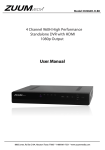
www.inmotioncctv.com
inDVR400RT Series Recorders
Quick GUIDE Book
CONTENTS
inDVR400RT Quick Guide
HDD Installation and Formatting
Back Up Video to USB
Search and Playback
Set up for Motion Events
E-Mail Alarm Events
Search and Playback
Remote connection using Auto ID
inDVRL400RT Series
Digital Video Recorder
Quick Guide
This manual is to help you set up your DVR in a basic manner, and playback or remote access your DVR.
Please see the User Manual on included CD for more detailed instructions.
Rev 4182012
Table of Contents
1.
2.
3.
4.
Important Safeguards and Warnings........................................................................................................ 2
Package Contents .............................................................................................................................. ...... 2
Hard Disk Installation if not pre-installed ............................................................................................... 2
Front Panel
炷Some products have this function, please take actual machine mode as quasi炸 ..... 3
Rear Panel(please take actual machine model as quasi).......................................................................... 4
Remote Controller .............................................................................................................................. ..... 5
Basic Operation .............................................................................................................................. ......... 5
7.1 Login System............................................................................................................................... ...... 5
7.2 Live View .............................................................................................................................. ............ 5
7.3 Status and Tool Bar(Please take actual machine model as quasi) ..................................................... 6
7.4 HDD Management ............................................................................................................................ 6
7.5 Record Setting .............................................................................................................................. ..... 6
7.5.1 Manual Recording .................................................................................................................. 7
7.5.2 Schedule Recording................................................................................................................ 7
7.6 Video Playback .............................................................................................................................. .... 7
7.7 File Back Up............................................................................................................................... ....... 7
7.8 PTZ Control............................................................................................................................... ........ 8
7.9 Network Settings .............................................................................................................................. . 9
8. Web Operation.............................................................................................................................. ........... 9
9. Mobile Phone Support.............................................................................................................................. . 11
10.Remote Viewing of DVR Video Footage via Auto ID ............................................................................. 14
5.
6.
7.
1
1. Important Safeguards and Warnings
x
x
Don’t place heavy objects on the DVR. Avoid dropping or striking the DVR.
Keep the DVR in a normal room environment, between -10oC ~ +40oC, away from any direct heat
source like direct sun light. Please do not install the DVR in a damp, smoky, or dusty environment.
Do not let solids or liquids fall into or infiltrate the DVR.
x
x
x
Please install the DVR on a flat surface.
Use within the power and surge protection rating.
Don’t disassemble or try to repair the DVR by yourself. Attempts to do so will void manufacturer’s
warranty!
x
To avoid HDD damage, do not move the DVR when in operation.
2. Package Contents
Your DVR package should come with the following items:
x
x
x
x
x
x
x
DVR
Remote Control
Power Adapter and Power Cord
Installation CD (with full manual and DVR software)
This Quick Guide
Mouse and USB Drive
HDD Installation and Format Quick Guide
3. Hard Disk Installation if not pre-installed
Your HDD needs to be installed before you can start recording. Some DVRs come with pre-installed hard
drive. If so, please check that the HDD has been formatted (7.4 HDD Management ). Otherwise, please
install HDD as following:
1) Open case by removing screws from back and sides of DVR.
2) Please connect the HDD in the standard way, screwing the HDD into the HDD brackets or DVR base.
All necessary cables are delivered with the DVR. Use instructions that came with the hard drive for exact
wiring and installation. Please connect the power cable to the appropriate socket, and the data cable to its
corresponding connector.
3) Close case and re-screw the screws to secure.
Power connector
Data connector
Please format the HDD before first use. ( 7.4 HDD Management ).
2
4. Front Panel
炷Some products have this function, please take actual machine mode as quasi炸
Type
Name
Introduction
Control Button
Use arrow buttons to move among the menu items.
Enter
Press the “Enter (
)” key to confirm your
choice. On live view the “
” key functions as a
PTZ control key.
Menu/Exit
Access tool bar/Hide tool bar/Exit menu/Exit sub
menu
Rewind
ŻŻ
Play/Pause
Stop
Ŷ
Fast Forward
ŹŹ
REC
Ɣ
Channel Selecting
Button(4CH/8CH)
Channel Selecting
Button(16CH)
Mute ON/Mute Off
ǃ
Number 0~9
Buttons/ ǃ
Rewind video during playback˗
Opens video search and playback menu. When the
playback mode is activated, press this button to
play/pause playback.
Stop playback
Fast forward video during playback
Start or Stop manual recording.
Using these buttons you can choose to output video
on your monitor either as a full-screen view of each
of the cameras individually (Channels 1 through 4/*8
depending on the model), or from all Channels
simultaneously ( / ).
Using the number buttons you can choose to display
video on your monitor either as a full-screen view of
each of the cameras individually (Channels 1 through
” with other
9), or you can combine button “
buttons to select channels among Channel 10 and
Channel 16. Pressing the button “
” to switch
display modes.
Turn the sound on or off.
Spot View
Using this button to enable auto sequencing.
Power Off
Turn off the DVR.
LEDs
Power LED/REC LED lights indicate your connection to the power
LED/ Net LED supply, recording status and net status.
Note: On live view press the button
or
or numerical button
ten times when there is no
tool bar, this will switch the main menu between CVBS video output and VGA video output.
3
5. Rear Panel(please take actual machine model as quasi)
8CH˖
16 CH˖
1. USB connectors
Use these USB ports to connect the mouse and backup devices (flash drive, DVD recorder).
Note: On some models, the USB port is on the side panel or on the front panel.
2. Audio Output Connector---- (optional) ˄Please take actual machine model as quasi˅
1 channel audio output, for connecting speakers (8ch/16ch-DB9)
Note: There are two video output connectors for 16 CH and there are the same as each other.
3. Audio Input Connectors (AUDIO IN 1-8/1-16) ˄lease take actual machine model as quasi˅
8/16 channels audio input, for connecting audio signal (8ch/16ch-DB9)
4. Video Input Connectors (1-8/1-16)
8/16 channels video input, for connecting analog video signal input, BNC (1Vp-Sȍ
5. Video Output Connector
Video output for connecting monitor or TV, BNC (1Vp-Sȍ
6. VGA Connector
For connecting VGA/LCD monitor
7. Ethernet Connector
RJ-45 10/100 Base-T Ethernet network
8. Alarm Input Connectors (8ch-ALARM IN 1-4/16ch-Alarm in 1-16)
For connecting to external sensor device
Each alarm has one input pin on the Terminal Block of the rear panel.
Connect positive (+) output pins of the device to the input slots (Alarm In) on the DVR terminal block (1
-4/1-16).
Connect ground (-) output pins of the device to the DVR Ground slots (G). Multiple devices can be
connected to one ground slot.
4
8CH
Alarm Output Connectors (pin NO-COM)
For connecting to external alarm device
RS-485 Connector (pin A-B)
For connecting PTZ camera control
9. Power Input Socket (12V DC)
10. Power Switch
11. Cooling fan
12. Ground – Ground the machine if necessary
13. Spot Video output (16ch)
16. HDMI Video Output(16Ch)
17. PTZ ---- (optional)
16CH
6. Remote Controller
The functions of remote keys are as the same as front panel. Detail introduction please refer to section 4
Front Panel.
7. Basic Operation
Note: During configuration, press button
to restore to default setting, press button
parameter, the parameter will take effect after clicking button
.
7.1 Login System
In live view, press the button “
” twice or double-click right
key of mouse in live view to display the tool bar, the login
window will appear if the password is enabled. You can fill in
user name and password to login.
Note: 1. The default password for Admin is “888888” and default
password for user1 is “666666”.
2. The Device ID is used for connecting the IE interface.
For detail operation please reference appendix 9 of the detail
guide CD.
7.2 Live View
Displayed on the live screen are the real time images, name and
state of each channel. Channel icons indicate the following:
Icon indicates that the channel has detected motion in the
motion detection mode.
5
to save
Icon indicates that the channel has detected sensor alarm in the alarm mode.
ƔRed dot indicates that the channel is running in the mode of recording.
7.3 Status and Tool Bar(Please take actual machine model as quasi)
1) In live view, press the button “
” once or click right key of mouse on live view to display status bar,
it will appear the status bar as following.
System time
Approximate Remaining Hours of HDD recording
” twice or double-click right key of mouse on live view to display
2) In live view, press the button “
tools bar if password is disabled. When password is available, you can see it after login.
PLAY
KEYLOCK
SEQ
EZOOM
Advance
SYSTEM SETTINGS
MUTE ON/MUTE OFF
MANUAL REC / STOP MANUAL REC
PTZ (Some products have this function)
Click the “ADVANCE” button and the screen will display the following figure:
Hide Advance PIP*1
PIP*2
VO SWITCH
QUAD
6 SHOW
7.4 HDD Management
If you have not yet installed a hard disk drive HDD into the
device, or the device didn’t read the HDD, or a new HDD
hasn't been formatted, or there is no space of the HDD to
” in the video preview
record, it will display an icon “
interface. You must format the HDD in the DVR before
first using. The steps as follows: System settings >
SYSTEM > HDD management > format.
7.5 Record Setting
&OLFN>7RRO%DUĺ6\VWHPVHWWLQJVĺ5HFRUG@WRHQWHU
[Record] menu. You can set quality, resolution, frame
rate, pack time and record mode. There are three record
modes: Manual Record, Always and Schedule. Always
record mode will record with every channel all the time.
Frame Rate: It is possible to adjust each channel frame
rate independently. Real-time recording is considered 25
frames per second (fps) for PAL and 30fps for NTSC.
6
8 SHOW
9 SHOW
Depending on TV system, for 8CH the maximum frame rate is either 200 (PAL) or 240 (NTSC) fps in CIF
resolution, 100 (PAL)/120(NTSC) fps in HD1 resolution, and 50 (PAL)/60(NTSC) fps in D1 resolution. For
16CH the maximum frame rate is either 400 (PAL) or 480 (NTSC) fps in CIF resolution, 200
(PAL)/240(NTSC) fps in HD1 resolution, and 100 (PAL) / 120 (NTSC) fps in D1 resolution.
Please note that the recording frame rate limit varies depending upon the recording resolution selected.
Even though you may set the recording frame rate here, the system will automatically downgrade the
recording frame rate if it exceeds machine limitations.
Resolution: The recording resolution has three options: D1ǃHD1 and CIF resolution. Standard Quality TV
is equivalent to D1 quality. The resolution of each channel for recording can be adjusted independently.
7.5.1 Manual Recording
Manual recording is useful for times when you want to immediately record something on screen. To turn on
manual recording, cOLFN>7RRO%DUĺManual Record]or hit the REC button on the front panel or the remote
control. A red button will appear in the lower left hand corner. To turn off the manual recording, press the
REC button again.
7.5.2 Schedule Recording
It allows you to create a schedule for recording tasks
throughout the week, so that only certain selected events
are actually recorded on the HDD.
CHANNEL: You can select all channels or just one
channel.
There are five modes for recording: MD recordˈNORMAL
recordˈNO RECORDˈI/O record and MD,I/O record.
Different colors signify different recording modes: Orange
means MD record ˈ green means normal record ,
grounding means no record ,deep red means I/O record and
red means MDˈI/O record.
After you complete the schedule you activate it by clicking
the [
] button.
7.6 Video Playback
&OLFN >7RRO %DUĺ 6\VWHP VHWWLQJV ĺ 3OD\@ WR HQWHU
[Playback] menu.
Method 1: playback by date
Date input: Adjust the date and time to match the recording
you are searching for: first, select “TIME” and press “Enter”
to input numbers directly to set the year, month, and date;
QH[W LQSXW WKH WLPH LQ WKH QH[W ILHOG DQG FOLFN ³Ź´ $
window that reads “CHOOSE PLAYBACK CHN” (see the
following right or above) will automatically appear; in this
ZLQGRZFKRRVHFKDQQHORIWKHYLGHRWREHSOD\HGDQGFOLFN³Ź´,IRQO\RQHFKDQQHOLVVHOHFWHGWKHYLGHR
from that channel will be displayed in full-screen mode. If two or more channels are selected, the videos
from the selected channels will be displayed simultaneously over four frames.
Method 2: playback by recording status:
Input the date, clickǏsearchǐand you can see the recording status on this date.
7.7 File Back Up
&OLFN >7RRO %DUĺ 3OD\ ĺ 6HDUFK@ WR HQWHU ILOH OLVW ,Q WKLV LQWHUIDce, you can back up video file. Click
[
]ǃ[
]ǃ[
] and [
] to switch page, select the video file you want to back up and click
] to back up the video file to USB disk.
[
7
U-DISK backup by time
Move the cursor to ǏŹǐ(the icon will be highlighted when selected) and left click to enter into the [REC.
6($5&+@VHWWLQJLQWHUIDFHRUSUHVVWKHEXWWRQ>ŹŒ@WRHQWHULQWRWKHVHWWLQJLQWHUIDFHPRYHWKHFXUVRUWR
option “U-DISK backup by time” and press the [ENTER] button or left click to access the U-DISK backup
by time Search(as shown in the figure below).
7.8 PTZ Control
Double-right click to enter toolbar menu under the real-time monitoring frame, and choose “PTZ” or press
the “ENTER” key to enter the control frame.
In the PTZ control frame, press the [
] button or right click, and a “
” icon will appear in the
upper right corner of the screen.
[PTZ Direction Control] From the PTZ control frame, move the mouse to the upper, lower, left and right
locations of the current frame, and this time, left-click and hold the mouse. Enter the control area of the
corresponding location.
In “
´PRGHXVHWKHPRXVHRUWKH>Ÿ@>ź@>Ż@>Ź@EXWWRQVRQWKHUHPRWHFRQWUROor the DVR’s front
panel to control the direction of the speed dome. 7KH³UHZLQG´ŻŻDQG³IDVWIRUZDUG´ŹŹEXWWRQV
can also be used to adjust magnification.
[SPEED] Regulate the rotating step length of the PTZ by using the slide bar. This function is mainly for the
controlling the speed. The larger the value, the faster the rotational speed will be, with possible values
ranging from 0~63(with a speed value of “0”, the camera will not rotate).
[IRIS ˉǃ
ǃIRIS +] This regulates the diaphragm.
[FOCUS ˉǃFOCUS+] This brings objects into focus finely.
8
[ZOOM ˉǃZOOM+] Pressing this causes the lens to zoom in and out. Magnification can be changed by
using the mouse wheel under the current frame.
Note: You have to configure parameters before control Pan-Tilt-Zoom and you can access PTZ setting by
FOLFNLQJ7RRO%DUĺ6\VWHP6HWWLQJĺ37=
7.9 Network Settings
To connect the DVR to the internet, certain settings must be input into the DVR. To access your DVR from
the internet, you will need either a Static IP from your internet service provider (ISP) or a router with
Dynamic DNS (DDNS) capability and an account with an online DDNS service. This service is country
specific, but in many countries, the manufacturer suggested service is http://www.dyndns.com. If the below
is not clear, please contact your network administrator for help or consult the full DVR manual on the
included CD.
Bring up the network settings menu via [7RRO%DUĺ6\VWHP6HWWLQJĺ1HWZRUN]. The four sub-menus are
“network setup”, “DDNS”, “email” and “mobile”.
On the menu of “network setup” to set up network type, including Static IP/ DHCP/PPPOE.
Static IP: If this is selected, please type in an IP address, subnet mask and gateway.
DHCP: If this is selected, a DHCP server should be set within the network. A dynamic IP address will be
assigned automatically and displayed in the IP Address field.
UPNP: Universal plug and play. If you turn it off, you should manually mapped its port to get mapped IP
address; if you turn it on, it will mapped DVR’s ports automatically.
Note: You should turn on UPNP on your router before turning on UPNP on DVR.
MEDIA PORT: Transfers video data between client and device. Default value is 9000.
WEB PORT: Sets up the port of IE browser via HTTP. Default value is 8090.but model dependent.
SETUP PORT: This port is fixed and you can’t modify it, the value is 8000.
DNS: Press [Enter] and input numbers for the net mask.
Mobile Port: Default value is 10510.
IP access: Including disable, forbidden, allow access.
8. Web Operation
1. Connect the DVR to the internet.
2. Make sure all the ActiveX controls for internet security on your PC are enabled. For I.E. this is through
[Tools->Internet Options->Security]. Also, see page 12-13 for Internet Explorer troubleshooting tips if
your application fails to open. This is the AUTO ID section, but can be used to troubleshoot IE
problems too.
3. After finishing the aforementioned settings, open the IE
browser, input http://192.168.0.X (192.168.0.X is is an example
of the IP address. Confirm the correct address from the DVR
network screen. For External public IP addresses, confirm the
correct address from your router.) and confirm. The :P represents
Web port number specified in the network setup. Default port
number assigned is 8090. You must add the colon and port
number to the IP address to connect to the DVR Then, please
click “If your browser does not support the ActiveX to download,
please click here”, the network will download and install the
control automatically.
After connecting to the internet, IE will automatically download the file to PC. After download, an interface
will prompt you to login system.
After filling in right user name and password, you can see a monitor interface as picture shows.
Default user ID is: Admin (with all administrative privileges). Default password is: “888888”.
9
10
10.Mobile Phone Support
This DVR device can transmit live feed from the CCTV cameras to your mobile phone, so that you can
have ‘on the go’ access to your surveillance system from virtually anywhere. To view, you must install a
mobile operating system specific program into your mobile. The mobile programs are located on the
included CD, or downloaded via iTunes for the iPhone. In iTunes, please search for “MobileEye+”. Please
see the instruction manual for your mobile to install the program. Currently, there are a limited number of
phones that are supported: Windows CE Mobile, Nokia Symbian S60 3rd and 5th Edition OS, Google
Android, BlackBerry OS 4.x+ and Apple iPhone.
Note:
1. Prior to using this feature, you should apply for an Internet connection service for your mobile
phone, such as 3G or 2.5G. Please contact your mobile service provider for details.
2. You can only watch one live feed channel at a time with your mobile phone. Split mode and
playback of recorded files is not available at the moment.
In the following example, we use the iPhone. The usage of other mobile programs is substantially similar.
For more detailed instruction, please view full user manual on included CD.
1) MobileEye+ installation
Open iPhone App store “
ᬅ Touch “
ᬆ Press “
“
” as follows:
” and search for “MobileEye +.” It is a free application.
” and the following screen will appear.
” Loading: this indicates that the “MobileEye +” software is downloading. When the “
11
” process
bar displays a “
”status, the MobileEye + software has finished installing.
Your personal account and password for the iTunes store will be necessary for download.
After download completion Waiting and the Loading, touch icon to open
This first example is using Mobile Eye+ and a known IP Address or Static Address:
Touch menu wheel at lower right
Touch on Add:
Touch on Device Name:
Touch to type Device Name, this can be anything you wish and then Done when complete:
Touch on Device IP:
Type in known IP address for your DVR and then Done when complete
12
Touch Device Port:
Type in port you have set in DVR and forwarded in router and Done when complete shown above. Default
is 10510
Touch User Name:
Type in Admin (Capital A in Admin) and then Done
Touch Password:
Type in Password you have saved for Admin, it is 888888 by default, then press Done:
Touch on Device Channels and select the channel number accordingly to your unit:
Touch Save at the top right:
Always Start from your Device screen and touch the Blue arrow:
13
Touch Live Video:
Make sure you have done your port forwarding and after a few moments depending on bandwidth 4
channels of Live Video will appear: Refer to Users Guide for more detailed information.
11.Remote Viewing with Auto ID
The Auto ID is used for connecting the DVR to an Internet browser interface. For detailed
instructions, refer to the following instructions. .
1. The ID number of each product is set in the factory. From the toolbar, click “System Setting”, and select
“user”. The screen will display the user management menu, and the DVR’s ID number will appear at the
top of the screen (as in the following illustration):
2. Then, open the main menu, click “Network”, then click “Other Settings” and select “Auto ID”, to access
the “Auto ID” option
14
3. In order for the Auto ID function to work, you must have opened the correct ports and forwarded them to
the DVR IP address on your LAN. Example of D-link router is below:
4. Once the network is connected, enter “http://www.ipremoteview.com” in the address field of the Internet
browser. Then enter the DVR ID number into the “Product ID” field, as shown in the following screenshot.
15
Note˖If after following the preceding instructions the login page does not work or the Auto ID function
fails, try the following steps to add the website to the zone:
Pay attention to any pop-up blocks:
Click on Options for this site and Always Allow:
The page will refresh and you will need to enter your AUTO ID again and click Submit.
You will be redirected to the Main Page for DVR log in. These steps are typical for your initial installation
and connection only. The page will ask you at the lower screen to run the.ocx, Click Allow:
16
After clicking Allow, if using Internet Explorer 8 or above, you will need to click the Compatibility Mode
at the top right of the screen:
Your PC will ask you to install the Active X component by JOUTEK ELECTRONICS. Click YES to
install.
After a few moments, depending on download speed you will receive the inMotion login page: Type in
your ID and Password to Connect: Default is Admin and 888888
(Capital A in Admin)
5. After the connection has been established, the Web Application Management (see the following figure)
will appear:
1-214-960-4640
inMotion CCTV, Inc. USA
519 Bennett Lane炽 Suite 100炽Lewisville炽Texas炽75057
inMotion CCTV, UK LTd.
Genesis Centre炽 Innovation Way炽Stoke on Trent炽ST6 4BF炽United Kindom Website:
www.inmotioncctv.com
17
+044-1783- 366080
inDVRL400RT Series
Digital Video Recorder
HDD Installation and Format Quick Guide
inDVRL408RTN / inDVRL408RTP / inDVRL416RTN / inDVRL416RTP
REV 7272012
HDD Installation and Format Quick Guide
Use supplied: USB mouse, HDD screws, HDD Rail attachments and 12VDC Power Supply
You will need: Phillips Screwdriver, Monitor with VGA or Composite input and HDD (not supplied)
1. Remove screws from side and rear of the top panel if applicable. 4 screws are factory installed 2
on each side. 6 black screws remain in accessory package for top cover installation after HDD is
installed.
2. Find HDD rails and screws in accessories, attach to the sides of the HDD and then to the bottom
panel of the DVR as shown: (Please visit www.inmotioncctv.com for approved HDD listing)
1
3. After tightening all screws to hold down your HDD, attach the provided power and SATA cables
as shown below: (Always be cautious when handling your HDD, any shock, drop or mishandling
can result in damage to the platter. See manufacturer warning recommendations)
*1TB Western Digital drive is shown as an example only.
2
4. Put top cover back on and tighten outer black screws. Pay attention to all your cables, so they
are not caught on any sides of the cover or HDD.
5. Attach the DVR with your monitor output; insert the USB mouse and Power on the DVR with
supplied power supply.
6. After the DVR has powered up, right click twice to receive the LOGIN screen:
Log into the Admin Screen
Default Password: 888888
Click Enter
Click Blue Check mark to enter programming
3
Click Cog Wheel to access menu settings
Click on the Arrows next to HDD in the SYSTEM menu:
After your HDD is recognized, it will appear in the HDD MANAGEMENT menu. Click for a check next to it:
Next, click on FORMAT HDD icon:
4
The inDVR will ask you to CONFIRM. Please remember all data will be erased if data exists. Click
CONFIRM:
You will receive a Formatting message. This will take a few moments depending on storage sizes to
format:
5
Click CONFIRM after complete:
Click the Blue Check at the lower right to APPLY:
Click on CONFIRM again:
6
Click the Red X to Exit HDD MANAGEMENT:
Click the Red X again to exit the SYSTEM MENU and return to the Live Screen:
7
inMotion CCTV, Inc. USA
519 Bennett Lane炽 Suite 100炽Lewisville炽Texas炽75057 1-214-960-4640
inMotion CCTV UK LTd.
Genesis Centre炽 Innovation Way炽Stoke on Trent炽ST6 4BF炽United Kindom 01783 366080
Website: www.inmotioncctv.com
8
inDVRL400RT Series Recorders
Backing up video to USB
This guide will help you back up video to a USB.
Please review “Search and Playback Using Channel, Time and Date” or “General Search and Playback”
to assist you in finding the proper times to load on your USB.
Log into the Admin Screen
Default Password: 888888
Click Enter
Click Blue Check mark to enter programming
1
REV7272012
Click on Play Icon:
After identifying the proper video channel(s)and time to backup, click on the U-DISK backup by time
icon:
Click on the dropdown arrow next to All Record. This is selected by default, you can also choose
between Normal recording (Continuous) Motion Recording, and I/O which is Alarm Recordings:
2
In this example, I will select Normal Record; now click in the date field to change the date:
Use the red arrows to move your selection and change the date:
Then click Enter:
Now click in the Start time Field. This is where you want to start the backup time to your USB:
Use the red arrows to move, select your start time, and then click enter. I have used 12:30 in this
example. A 24 hour clock is used to distinguish between am and pm.
3
Now click in the End time Field. This is the end of the video you need on USB:
Move and change to the end time desired and click enter:
By default, all channels are selected for backup. Un-check any channels you do not wish to back up
video from the previously selected Start and End time:
In this example, I need channel 7, on 04/03/2012, from 12:30 am to 12:35 am:
4
Now click the Backup icon:
You will be asked to choose between two formats, AVI and H.264.
AVI is a video format which you should be able to watch using Windows Media, VLC or GOM Player*
H.264 is a proprietary inMotion format which will need to be used with HS Player to be viewed. HS
Player is on the disc that came with the DVR.
In this example, I have chosen AVI.
5
Please wait until the DVR lets you know the backup is finished and you confirm before you remove
the USB. This will happen after the 100% screen:
After you confirm click the Red X in the backup screen:
And then again in the Play screen to go back to Live Video:
You are now read to remove your USB from the inDVR and play on your PC.
*Depending on age of your player, Windows Media for example, you may not have the codec to play
the file. Make sure you have the latest updated Player by visiting the proper manufacturer’s website.
inMotion CCTV, Inc. USA
519 Bennett Lane炽 Suite 100炽Lewisville炽Texas炽75057 1-214-960-4640
inMotion CCTV UK LTd.
Genesis Centre炽 Innovation Way炽Stoke on Trent炽ST6 4BF炽United Kindom +044-1783-66080
Website: www.inmotioncctv.com
6
inDVRL400RT Series Recorders
Search and Playback Using Channel, Time and Date
This guide will help you search and playback by time, date and specific channel (s).
Log into the Admin Screen
Default Password: 888888
Click Enter
Click Blue Check mark to enter programming
1
Click on Play Icon:
At top left, click on arrow next to ALL and select desired Camera number to begin. In this example
Channel 7 will be used:
Click the Search icon:
2
After the DVR has completed the search process your calendar will display all days in which there is
recording. In example shown, all days are green for normal/continuous recording. Other colors are;
Orange if recording is in Motion Detection and Red for Alarm Inputs:
Double click on desired day to review in Calendar. I have selected the 21st in this example:
3
Click in the Hour area next to the Date Located in the TIME section up top:
Click on the Red Arrows to move the indicator and change the numbers according to your time
desired:
In this example, I have selected 16:35 and now click on Enter:
4
Now click the Search icon at the top:
Then click the Play icon:
In case you may need to playback more than Channel 7, by default all cameras are selected. Please
uncheck cameras you do not wish to view:
In this example, I will leave only Channel 7 selected and click the Play icon:
5
During the Playback screen, all playback functions are at the bottom including a digital zoom function.
After selecting digital zoom, right click and drag to create the area to zoom in.
Right click back out.
6
inMotion CCTV, Inc. USA
519 Bennett Lane炽 Suite 100炽Lewisville炽Texas炽75057 1-214-960-4640
inMotion CCTV UK LTd.
Genesis Centre炽 Innovation Way炽Stoke on Trent炽ST6 4BF炽United Kindom +044-1783- 366080
Website: www.inmotioncctv.com
7
inDVRL400RT Series Recorder
How to send e-mail events from the DVR.
This guide will help you set up your DVR so you can send e-mails upon event activations by
Motion Alarm or by Alarm Trigger.
Log into the Admin Screen
Default Password: 888888
Click Enter
Click Blue Check mark to enter programming
Click Cog Wheel to access menu settings
1
Click on network tab on the right then select the arrow key next to Email to access the Email set up
menu.
Email: Select On to activate the EMAIL function
SSL: SSL is a security link transport protocol that can be used to encrypt information communicated over
the Internet (including email) to prevent hackers from accessing the email communication or other
information of users on a network, such as passwords.
Interval: This indicates the interval for sending email include; the options are: 5s, 10s, 30s, 1 minute and
3 minutes.
SMTP Port: This refers to the port of the SMTP server. Generally, the SMTP port number is “25”, but
there are exceptions; for example, the SMTP port number of Gmail’s server is “465”.
SMTP: This indicates server address used by the DVR user.
Sender: In this field, enter the sender’s email address. The email address should be consistent with the
server being used. That is, if the sender’s email address is [email protected], the corresponding server
should be “smtp.gmail.com”.
Receiver: In this field, enter the receiver’s email address (the email address being used to receive images
transmitted from the DVR’s motion-detection alarms).
After filling in all appropriate information select the Blue Arrow to save the data
Select Confirm then close the e-mail setup window by selecting the
This completes the EMAIL setup now you will need to program the I/O alarm function
2
Select the Alarm tab at the left to access the alarm setup menu then select the arrow next to I/O
alarm. Proceed to fill out information for each channel that will be set up.
CHANNEL: From this field, select the channel to be set up.
I/O ALARM: Each channel corresponds to an I/O status (see the following status explanations), which
means that when an alarm is triggered, it will activate the corresponding channel to start alarm
recording.
I/O status types:
N.O.: “Normally open”: It means that in its normal state, the sensor is kept under constant low voltage. If
the sensor voltage changes from low to high, then the alarm will be triggered.
N.C.: “Normally closed” (also referred to as “normally connected”): The normal state of the sensor is
under constant high voltage. If the sensor voltage changes from high to low, then the alarm will be
triggered.
OFF: Set the I/O to “Off” if external sensor alarms are not in use.
OUTPUT: ͞я” indicates that an alarm will sound if it had been triggered by sensor.
RECORD: ͞я” indicates that the relevant channel will record if it has been triggered by activity detected
by the sensor.
BUZZER: ͞я” indicates that the buzzer will sound if it has been triggered by activity detected by the
sensor.
Prerecord: ͞я” indicates that the relevant channel will prerecord for 5 seconds if it has been triggered by
activity detected by the sensor.
Email/FTP: ͞я” indicates that the picture of relevant channel will be sent to the pre-registered email
address and FTP if it has been triggered by activity detected by the sensor.
3
After filling in all appropriate information select the Blue Arrow to save the data
Select Confirm then close the I/O setup window by selecting the
This completes the I/O setup, if triggering by motion alarms continue to the next section.
Select the Alarm tab at the left to access the alarm setup menu then select the arrow next to Motion.
Proceed to fill out information for each channel that will be set up.
CHANNEL: In this field, select the channel to be configured.
SWITCH: Each channel has a corresponding channel switch; press “Enter” to turn the motion detection
for each channel on or off.
SENSITIVITY: Each channel has a specific sensitivity setting; there are eight levels, with “1” being the
highest level of sensitivity; press “Enter” to adjust the level.
MD AREA: Sometimes, it is necessary to have some regions in the camera’s coverage area enabled with
the motion detection feature, while other regions in the same coverage area do not require this
functionality. This may be handy when, for example, the camera covers the road and an adjoining area.
While it would be useful to have the motion detection enabled on the area near the entrance to a
building, it would most likely not be helpful to see it triggered every time a car or truck passes by on the
nearby road. Each channel has a specific regional motion detecting setting.
To enter the “Regional Setting” menu, move the cursor to “setting”
and then press “Enter.” When viewing the selected channel’s coverage
area using the MD Area option, the blue area is where motion
detection is activated, and transparent block is the area where motion
detection is not activated.
4
Press the direction keys on the remote control to move the cursor along the small pane: the position of
cursor is indicated by a green frame. Press “Enter” to select or cancel motion detection in this small
pane. When the setup is finished, press”
“or right click to return to the MD setup menu and click
“
” to save the settings.
Note:
Mouse operation: Left-click and drag the frame to set up the region for motion detection.
OUTPUT: ͞я” indicates that an alarm will be activated if it has been triggered by motion.
RECORD: ͞я” indicates that the selected channel will record if it has been triggered by motion.
BUZZER: ͞я” indicates that the buzzer will sound if it has been triggered by motion.
Prerecord: ͞я” indicates that the relevant channel will prerecord for 5 seconds if it has been triggered by
motion.
Email/FTP: ͞я” indicates that a picture of selected channel will be sent to the pre-registered email
address and FTP if an alarm has been triggered by motion.
Mobile Alarm: “я”indicates that an SMS message will be sent to the pre-registered phone number when
a motion-detection alarm has been triggered
After filling in all appropriate information select the Blue Arrow to save the data
Select Confirm then close the Motion setup window by selecting the
Connecting alarm points
The 8 Channel unit has 4 alarm inputs pins 1-4 and a common ground pin 5 for connection.
The 16 channel unit has 16 alarm inputs pins 1-16 plus common ground terminal.
Attached trigger points such as door contacts or motion detectors, these will trigger the DVR to tag
the video as an event and send your designated email address a message with a .jpg image.
8 Channel
16 Channel
5
Example email sent after event:
6
inDVRL400RT Series Recorders
How to set up your DRV to record on Motion Events.
This guide will help you put your inDVR from default Continuous Record in Motion Recording.
In this example I will put all cameras in Motion Detection. You may also put one camera or multiple
cameras in MD.
Log into the Admin Screen
Default Password: 888888
Click Enter
Click Blue Check mark to enter programming
1
Click Cog Wheel to access menu settings
Click on the RECORD section of Sub-menu:
Next to RECORD MODE at the bottom right, click on the drop down arrow next to ALWAYS:
Select SCHEDULE:
2
Click on the double arrows underneath SCHEDULE:
You are now in the Schedule screen, the default is in ALL cameras, use the drop down arrow to change
if necessary:
By default the selection is ready for Motion Detection selection, notice the check next to MD above.
Now you will click on the 00 hour block next to MON. and drag all the way to the 24 hour block at the
end of the day:
Click on COPY at the top right:
3
It is already setup to copy from MON to ALL days, so once you select copy, all days in the grid will turn
orange allowing motion detection on all hours on all days:
Select the Blue check at the bottom right to apply:
Click on Confirm:
Click on the Red X at the top right:
4
Click on the Blue check again to APPLY in the RECORD Sub-Menu:
Click on Confirm:
Over to the left, click on ALARM Sub-Menu:
It’s always a good idea to use PRERECORD, use the dropdown arrow next to it to change from OFF to
ON. PRERECORD is 5 seconds.
Click on the arrows next to MOTION:
5
Click on the dropdown arrow next to CHANNEL.
I will scroll down and select ALL for ALL channels:
Click on the dropdown arrow next to SWITCH, change from OFF to ON, this puts ALL channels in
MOTION DETECTION:
Click on the dropdown arrows next to SENSITIVITY, by default it is at 4 which is mid-range. Notes at
the bottom of the screen let you know that 1 is Highest if you wish to change:
Click on the double arrows next to MOTION:
6
This is the area where motion is detected. By default motion is detected in ALL areas, all grids are
shaded:
If you do not wish to have motion detected in a certain area, left click on the grid square to
“UNSHADE” the area and then right click to back out:
7
Save your parameters by clicking the Blue check at the bottom:
Click on Confirm:
Click the Red X at the top right to back out:
Click the Blue check to Apply again:
Click on Confirm:
8
Click the Red X at the top right to back out:
In your Live Screen, if you have selected Motion Detection for all channels, you should see a small
green motion icon at the lower portion of each channel, once the inDVR has detected motion.
If you have any questions, please feel free to contact us!
9
inDVRL400RT Series Recorders
Using Auto ID
This guide will help you setup your inDVR for Local and Remote View using Auto ID. Auto ID can be
used when there is no Static external IP address available.
Log into the Admin Screen
Default Password: 888888
Click Enter
Click Blue Check mark to enter programming
1
Click Cog Wheel to access menu settings
Click on NETWORK in Main Menu:
Click on the ARROWS next to NETWORK at top:
2
Click on the down arrow next to STATIC at top:
Click on DHCP:
Make special note for ports you have selected. In this example I have changed my ports to MEDIA
PORT – 9001, WEB PORT - 8091 and SETUP PORT - 8001. Click in each box and change the numbers if
needed. You will need these later for your router:
Click the blue check at the bottom to apply:
3
Click CONFIRM:
Click Red X at top to exit:
Click the ARROWS next to NETWORK again:
If you have connection with a router, you will be assigned an IP address. Make note of this address,
you will need it later:
Click the Red X at the top:
4
Back in the NETWORK submenu, click on the bottom arrows next to OTHER SETTINGS:
Make sure the AUTO ID is OPEN, should be by default:
Click on Red X to Exit again.
5
Click on SYSTEM in Main Menu:
Click on ARROWS next to USER:
Make note of your DEVICE ID. You will need this later. Each DEVICE ID unique per inDVR.
6
Click the Red X out of USER MANAGEMENT and then again on SYSTEM to return to the Main Live
Video Screen:
All information in the DVR is set.
Now it’s time to enter this information in your router.
There are many different routers, please visit http://www.portforward.com
Click on the Router Screenshots or Username and Passwords link to get detailed information on your
router model.
Each router is slightly different, in my example of the Dlink you can see I have entered the IP address
assigned to the DVR which was 192.168.0.101 and entered the ports for forwarding in both TCP and
UDP for 8001,8091 and 9001.
7
Once your port forwarding has been completed, you can now go to Internet Explorer and type in this
address: http://www.ipremoteview.com
You will type in your AUTO ID in this Product ID box and click Submit:
Once you type in your AUTO ID you will get a forwarding message, yours will be unique, the one
below is an example only:
Pay attention to any pop up blocks:
Click on Options for this site and Always Allow:
The page will refresh and you will need to enter your AUTO ID again and click Submit.
You will be redirected to the Main Page for DVR log in. These steps are typical for your initial
installation and connection only. The page will ask you at the lower screen to run the.ocx, Click Allow:
8
After clicking Allow, if using Internet Explorer 8 or above, you will need to click the Compatibility
Mode at the top right of the screen:
Your PC will ask you to install the Active X component by JOUTEK ELECTRONICS. Click YES to install.*
After a few moments, depending on download speed you will receive the inMotion login page: Type in
your ID and Password to Connect: Default is Admin and 888888
(Capital A in Admin)
Happy Viewing!
*If you do not get the Active X install message, make sure you have your Active X Security feature
enabled:
In Internet Explorer, Go to TOOLS -> INTERNET OPTIONS -> click Tab on SECURITY -> click on CUSTOM
LEVEL.
9
Enable like below:
Your PC should ask if you are sure for risk settings, please click YES.
10