1
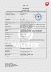
Page 1 of 36 TEST REPORT EN / IEC 62040-1 Uninterruptible power systems (UPS) – Part 1: General and safety requirements for UPS Report reference No . .................... : U12005-11 Tested by see cover page (printed name and signature) .......... : ..................................................... Approved by see cover page (printed name and signature) .......... : ..................................................... Date of issue ................................... : April 11, 2011 Total number of pages .....................: 36 pages A Plus Safety Consulting Co. Ltd. Testing Laboratory Name ............. : Address ........................................... : 7F, No. 163, Sec. 2, Tatung Rd., Shijr City 221, Taipei Hsien, Taiwan, R.O.C. Applicant's Name .......................... : Ablerex Electronics Co., Ltd. Address ........................................... : 1F, No.3, Lane 7, Paokao Rd., Hsintien 23114, Taipei Hsien, Taiwan Test specification Standard........................................... : EN 62040-1: 2008, IEC 62040-1: 2008 (1st Edition) Test procedure ................................ : Service of CE Marking in LVD Non-standard test method .............. : N/A Test Report Form No. .................... : IEC62040_1A TRF originator . ................................ : TÜV Rheinland Japan Ltd. Master TRF ..................................... : Dated 2009-11 Test item description .................... : Uninterruptible Power Supply Trademark ...................................... : Manufacturer ................................... : Ablerex Electronics (Suzhou) Co., Ltd. No.36, Wang Wu Road, Suzhou China. Model and/or type reference ........... : VT PRO1000, A03-S1001, VT PRO1500, Micro VT1500,A03-S1501, Guard_S 1000A, Guard_S 1000AP, ME1000, MO1000, ALL9100, Nemo 160, Nemo 200, Onda 10, Guard_S 1500A, Guard_S 1500AP, ME1500, MO1500, ALL9150, Onda 16, ABL. LB1000, ABL.LB1500. Serial number .................................. : N/A Rating(s) .......................................... : Models VT PRO1000, series : I/P: 230 V ac, 5.88 A, 50/60 Hz, 1Φ O/P: 230 V ac, 1000 VA, 600 W, 50/60 Hz, 1Φ Models VT PRO1500, series: I/P: 230 V ac, 8.82 A, 50/60 Hz, 1Φ O/P: 230 V ac, 1500 VA, 900 W, 50/60 Hz, 1Φ Page 2 of 36 Report No.: U12005-11 Copy of marking plate differences label: Summary of testing: This report shall not be reproduced except in full without the written approval of the testing laboratory. The tested samples were pre-production models without the serial numbers. Page 3 of 36 Report No.: U12005-11 Particulars: test item vs. test requirements Equipment mobility ......................................: Pluggable type A (Detachable power supply cord) Operating condition......................................: continuous Mains supply tolerance (%)..........................: + 10%, -10% Tested for IT power systems ......................: No, TN system IT testing, phase-phase voltage (V) ............: N/A Class of equipment .....................................: Class I Mass of equipment (kg) ...............................: <18 kg Protection against ingress of water .............: IP20 Test case verdicts Test case does not apply to the test object .: N/A Test item does meet the requirement .........: P(ass) Test item does not meet the requirement ...: F(ail) Testing Date of receipt of test item ..........................: March 8, 2011 Date(s) of performance of test ....................: March 8, 2011 to April 8, 2011 General remarks The test result presented in this report relate only to the object(s) tested. This report shall not be reproduced, except in full, without the written approval of the Issuing testing laboratory. ”(see Enclosure #)" refers to additional information appended to the report. "(see appended table)" refers to a table appended to the report. Throughout this report a comma (point) is used as the decimal separator. Standard IEC 62040-1:2008 is to be used in conjunction with IEC 60950-1:2006, which is referred to in this TRF by "RD". Page 4 of 36 Report No.: U12005-11 EN / IEC 62040-1 Clause Requirement – Test Result – Remark 4 GENERAL CONDITIONS FOR TESTS 4.5 Components P 1.5.1/RD General P Verdict Comply with IEC 60950-1 or relevant component standard (see appended table 4.3) P 1.5.2/RD Evaluation and testing of components Components which are certified to IEC and/or national standards are used correctly within their ratings. Components not covered by IEC standards are tested under the conditions present in the equipment. P 1.5.3/RD Thermal controls N 1.5.4/RD Transformers used are Transformers suitable for their Intended application and comply with the Relevant requirements of the standard and Particularly Annex C. The Interconnection cable Interconnecting cables contain only SELV Capacitors in primary circuits ..........................: X2 capacitor according to IEC 60384-14:1993 with 21 days damp heat test. P 1.5.7/RD Resistors bridging insulation N 1.5.7.1/RD Resistors bridging functional, basic or N 1.5.5/RD 1.5.6/RD P P supplementary insulation 1.5.7.2/RD Resistors bridging double or reinforced insulation between a.c. mains and other circuits N 1.5.7.3/RD Resistors bridging double or reinforced insulation between a.c. mains and antenna or coaxial cable N 1.5.8/RD Components in equipment for IT power systems 4.6 Power interface TN power system N P 1.6.1/RD AC power distribution systems TN power system 1.6.2/RD Input current (see appended table 4.4) P P Page 5 of 36 Report No.: U12005-11 EN / IEC 62040-1 Clause Requirement – Test 4.4 1.6.4/RD Neutral conductor Result – Remark Verdict Neutral is not identified in the N equipment. Basic insulation for rated voltage between Earthed parts and primary phases. Input neutral is directly connected to the O/p neutral. The unit maintains the TNSystem in the standby mode 4.7 Marking and instructions P 4.7.1 General P 4.7.2 Power rating 1.7.1/RD 1.7.1/RD See Label P Input rated voltage/range (V)............................: Ditto P Input rated current/range (A) ............................: Ditto P Input symbol for nature of supply (d.c.) ...........: The Equipment is for AC Supply P Input rated frequency/range (Hz)......................: Ditto P Number of Input phases and neutral…………… P Output rated voltage/range (V) ........................: Ditto P Output rated current/range (A) ........................: -- N Output rated power factor, (if less than unity, or active power and apparent power or active power and rated current)……………………… Ditto P Number of output neutral..................................: Ditto P Output rated active power (W) ........................: Ditto P Output rated apparent power (VA) ..................: Ditto P Output symbol for nature of supply (d.c.) ........: No d.c output P Rated frequency or rated frequency range (Hz): P Ditto Max. ambient operating temperature range Optional, 0-40°C mentioned (°C) ...................................................................: in the user manual. P Manufacturer name or trademark or identification mark ...........................................: P Type/model type reference...............................: See Label P Symbol for Class II equipment only .................: Class I equipment N Other symbols .................................................: N Certification marks ...........................................: N Page 6 of 36 Report No.: U12005-11 EN / IEC 62040-1 Clause Requirement – Test Result – Remark Instructions for units with automatic bypass/maintenance bypass, additional input a.c. supply, or external batteries, having text "See installation instructions before connecting to the supply" .................................: Verdict N The user manual contains information for operation, installation, servicing, transport, storage and technical data. P 4.7.3 Safety instructions 4.7.3.1 General P 4.7.3.2 Installation……………………………………....: P Location in a restricted access location only.. : N Permanent connector UPS .............................: N Pluggable type A or Pluggable type B UPS .. : P 4.7.3.3 Operation........................................................ : P 4.7.3.4 Maintenance................................................... : P 4.7.3.5 Distribution related backfeed.......................... : N 4.7.4 Main voltage adjustment ……………………….: N 1.7.4/RD Supply voltage adjustment .............................. : No adjustment necessary. N Methods and means of adjustment; reference to installation instructions ................................: N 4.7.5 1.7.5/RD Power outlets .................................................... : N 4.7.6 1.7.6/RD Fuse identification (marking, special fusing characteristics, cross-reference) ..................... : P 4.7.7 1.7.7/RD Wiring terminals P 1.7.7.1/RD Protective earthing and bonding terminals ...... : The symbol of was marked on the terminal block for connection of protective earthing conductor. P 1.7.7.2/RD Terminal for a.c. mains supply conductors ...... : The marking and indication of the AC mains supply neutral conductor on junction box cover are located that indication of function is clearly. N 1.7.7.3/RD Terminals for d.c. mains supply conductors .... : Only one supply from mains. N 4.7.8 Battery terminals .............................................. : Polarity of battery terminals is indicated according to IEC 60417, Nos. 5005 and 5006 (+ and -) on the battery. P 4.7.9 1.7.8/RD Controls and indicators P Page 7 of 36 Report No.: U12005-11 EN / IEC 62040-1 Clause 1.7.8.1/RD 1.7.8.2/RD 1.7.8.3/RD 1.7.8.4/RD Requirement – Test Result – Remark Identification, location and marking ................. : See below. Colours ...........................................................: No safety involved controls or indicators. Symbols according to IEC 60417 .....................: Functional power switch marked according to IEC 60417, No. 5009 (line half inside circle). Markings using figures ...................................: Ditto. Verdict N N P N 4.7.10 1.7.9/RD Isolation of multiple power sources .................: The markings of the functional power switch are on the switch. P 4.7.11 IT power systems N 1.7.10/RD IT power distribution systems Equipment was not applied for IT power system. N 4.7.12 Protection in building installations Not relied on building installation. N 4.7.13 5.1/RD High leakage current (mA) ..............................: Leakage current does not exceed 3.5mA P 4.7.14 1.7.10/RD Thermostats and other regulating devices N 4.7.15 1.7.2.1/RD Language(s) ....................................................: Safety instructions and markings were in English language. Other languages will be provided when submitted for national approval. The label and markings Durability of markings were subjected to the permanence of marking test. The label and marking were rubbed with cloth soaked with water for 15s and then again for 15s with the cloth soaked with petroleum spirit. After this test there was no damage to the label. The marking on the label and silk printing did not fade. There was no curling nor lifting of the label edge. Removable parts N 1.7.8.1/RD 4.7.16 1.7.11/RD 4.7.17 1.7.12/RD Not provided with thermostats and regulating devices. No required markings placed on removable parts. P Page 8 of 36 Report No.: U12005-11 EN / IEC 62040-1 Clause Requirement – Test Result – Remark 4.5.18 1.7.13/RD Replaceable batteries The statement was described in the user manual: Verdict Caution – Risk Of Explosion If Battery Is replaced By an Incorrect Type. Dispose Of Used Batteries According To The Instructions. Language(s) ....................................................: English 4.7.19 1.7.2.5/RD Operator access with a tool ..............................: A symbol was marked in the battery compartment where was visible easily. P 4.7.20 Battery P Batteries located in battery compartment inside UPS. A label with the information below is located close to the battery compartments. Clearly legible information ...............................: P Battery type ...................................................... : Lead acid P Nominal voltage of total battery (V) ................. : P Nominal capacity of total battery (optional) ......: P Warning label .................................................. : CAUTION: the lead acid battery may cause chemical hazard. P CAUTION: the battery presents a risk of energy hazard. Maintenance free battery. CAUTION: For disposal instructions for the battery, see users manual. Instructions ...................................................... : Sufficient information provided in the users manual regarding the battery replacement. P 2.1.1.5/RD Protection against energy hazards P 4.5.21 Installation instructions 1.7.2.4/RD UPS will be delivered with installed batteries. P 5 FUNDAMENTAL DESIGN REQUIREMENTS P 5.1 Protection against electric shock and energy hazards P 5.1.1 Protection for UPS intended to be used in operator access areas P Test by inspection ........................................... : P 2.1.1/RD Page 9 of 36 Report No.: U12005-11 EN / IEC 62040-1 Clause Requirement – Test Result – Remark Verdict Test with test finger (Figure 2A) .................... : P Test with test pin (Figure 2B) ......................... : P Test with test probe (Figure 2C) .................... : P 2.1.1.2/RD Battery compartments .....................................: N 2.1.1.3/RD Access to ELV wiring No ELV wiring in operator accessible area. N Working voltage (Vpeak or Vrms); minimum distance through insulation (mm) 2.1.1.4/RD Access to hazardous voltage circuit wiring 2.1.1.5/RD Energy hazards ................................................: No access with test finger to any parts with only basic insulation to ELV or hazardous voltage. See below P P The test pin can not touch hazardous voltage through any openings or seams within the appliance. 2.1.1.6/RD Manual controls see appended table 5.1.3 P 2.1.1.7/RD Discharge of capacitors in equipment No risk of electrical shock. P 2.1.1.8/RD Measured voltage (V); time-constant (s)........ : <1 sec P Energy hazards – d.c. mains supply a) Capacitor connected to the d.c. mains supply ………………… …………………... P <20J P b) Internal battery connected to the d.c. mains supply ....................................................... : N N 5.1.2 Audio amplifiers ............................................. : Protection for UPS intended to be used in service access areas 5.1.3 Hazardous energy level Protection for UPS intended to be used in restricted access areas Hazardous energy level Backfeed protection 2.1.1.9/RD 5.1.4 P N Shock hazard after de-energization of a.c. input for UPS…………………………………….. Measured voltage (V); time-constant (s)............ P <1V,1Sec P Page 10 of 36 Report No.: U12005-11 EN / IEC 62040-1 Clause Requirement – Test Result – Remark Description of the construction ........................: The input is disconnected in line and neutral from the output in backup made and separated with a gap of =1.4mm from one input (L/N) pin to the other input (L/N) pin. Verdict P The detection circuit are connected before the backfeed relay. However these circuits were isolated by photo couplers to secondary control circuits. No hazardous voltage in backup mode at user accessible wiring connection of terminal block. 5.1.5 Emergency switching device N 5.2 Requirements for auxiliary circuits P 5.2.1 Safety extra low voltage circuit - SELV N 2.2.1/RD General requirements N 2.2.2/RD Voltages under normal conditions (V) ............. : N 2.2.3RD Voltages under fault conditions (V) ................. : N 2.2.4/RD Connection of SELV circuits to other circuits .. : Telephone network voltage circuits - TNV N 2.2/RD 5.2.2 No TNV circuit. N 2.3/RD 2.3.1/RD Limits N 2.3.2/RD Type of TNV circuits.......................................: Separation from other circuits and from accessible parts 2.3.2.1/RD General requirements N 2.3.2.2/RD Protection by basic insulation N 2.3.2.3/RD Protection by earthing N 2.3.2.4/RD Protection by other constructions ............ .... : N 2.3.3/RD Separation from hazardous voltages P Insulation employed ...................... ................ : N Page 11 of 36 Report No.: U12005-11 EN / IEC 62040-1 Clause Requirement – Test 2.3.4/RD Connection of TNV circuits to other circuits N Insulation employed ........................ .............. : Test for operating voltages generated externally N Test with test probe (Figure 2C) ................... : Limited current circuits N 2.4.1/RD General requirements N 2.4.2/RD Limit values N Frequency (Hz) ................................................. : Measured current (mA) ....................................: Measured voltage (V) .......................................: Measured capacitance (µF).............................. : 2.4.3/RD Connection of limited current circuits to other circuits N 5.2.4 External signaling circuits N 3.5.1/RD General requirements P 3.5.2/RD Types of interconnection circuits ...................... : P 3.5.3/RD ELV circuits as interconnection circuits N 3.5.4/RD Data ports for additional equipment N 5.2.5 Limited power source N a) Inherently limited output N b) Impedance limited output c) Regulating network limited output under normal operating and single fault condition N 2.3.5/RD 5.2.3 Result – Remark Verdict 2.4/RD 3.5/RD 2.5/RD d) Overcurrent protective device limited output Max. output voltage (V), max. output current (A),max. apparent power(VA) ……………..... : Current rating of overcurrent protective device (A)………………………………………………… N N 5.3 Protective earthing and bonding P 5.3.1 General 2.6.1/RD Protective earthing P 2.6.2/RD Functional earthing Protective earthing and protective bonding conductors General P 2.6.3/RD 2.6.3.1/RD P P Page 12 of 36 Report No.: U12005-11 EN / IEC 62040-1 Clause 2.6.3.2/RD Requirement – Test Size of protective earthing conductors Result – Remark P 2 2.6.3.3/RD Verdict Rated current (A), cross-sectional area (mm ), AWG : Size of protective bonding conductors P 2 Rated current (A), cross-sectional area (mm ), AWG : Protective current rating (A), cross-sectional area (mm2), AWG.................... ..................... : Resistance of earthing conductors and their Resistance, < 0.1Ω terminations; resistance (Ω), voltage drop (V), test current (A), duration (min) ...................... : Test current: 18A Integrity of protective earthing It is not possible to disconnect earth without disconnecting mains as terminal block is used. Interconnection of equipment N 2.6.5.4/RD Components in protective earthing conductors and protective bonding conductors Disconnection of protective earth It is not necessary to disconnect earthing except for the removing of the earthed parts itself Parts that can be removed by an operator 2.6.5.5/RD Parts removed during servicing N 2.6.5.6/RD Corrosion resistance 2.6.5.7/RD Screws for protective bonding N 2.6.5.8/RD Reliance on telecommunication network or cable distribution system N 5.3.2 Protective earthing P 2.10/RD Clearances, creepage distances and distances through insulation P 4.2/RD Mechanical strength N 5.2/RD Electric strength P 5.3.3 Protective bonding N 5.4 AC and d.c. power isolation P 5.4.1 General 3.4/RD Disconnection from the mains supply P 3.4.1/RD General requirement P 3.4.2/RD Disconnect devices P 3.4.3/RD Permanently connected equipment N 3.4.4/RD Parts which remain energized P 2.6.3.4/RD 2.6.5/RD 2.6.5.1/RD 2.6.5.2/RD 2.6.5.3/RD All safety earthing connections in compliance with Annex J. P P N N N P 2.6.1/RD Page 13 of 36 Report No.: U12005-11 EN / IEC 62040-1 Clause Requirement – Test Result – Remark 3.4.5/RD P 3.4.6/RD Switches in flexible cords Number of poles - single-phase and d.c. equipment 3.4.7/RD Number of poles - three-phase equipment N 3.4.8/RD Switches as disconnect devices P 3.8.9/RD Plugs as disconnect devices P 3.4.10/RD Interconnected equipment N 3.4.11/RD Multiple power sources N 5.4.2 Disconnect devices N 5.5 Overcurrent and earth fault protection P 5.5.1 General 2.7.3/RD Short-circuit backup protection P 2.7.4/RD Number and location of protective devices .....: Overcurrent protection by one or two circuit breaker in the rear of enclosure. P 2.7.5/RD Protection by several devices One or two circuit breakers. N 2.7.6/RD Warning to service personnel...........................: Hazardous voltage may be still present in the equipment after the circuit breaker opened. So that the below wording is required as suitable: P Verdict P Caution – Double Pole/Neutral Fusing. 5.5.2 Basic requirements Equipment relies on circuit breaker of the wall outlet installation protection of the building installation in regard to L to N short circuit. Overcurrent protection is provided by the circuit breaker. 5.5.3 5.5.3.1 Battery circuit protection Overcurrent and earth fault protection 5.5.3.2 Location of protective device 5.5.3.3 Rating of protective device 5.3.1/RD Protection against overload and abnormal operation 5.6 Protection of personnel – Safety interlocks N 5.6.1 Operator protection N P P P The fuse is directly located behind the supply wire from the battery. P P (see appended table 8.3) P Page 14 of 36 Report No.: U12005-11 EN / IEC 62040-1 Clause Requirement – Test Result – Remark 2.8/RD Safety interlocks N 2.8.1/RD General principles N 2.8.2/RD Protection requirements N 2.8.3/RD Inadvertent reactivation N 2.8.4/RD Fail-safe operation N 2.8.5/RD Moving parts N 2.8.6/RD Overriding N 2.8.7/RD Switches and relays N 2.8.7.1/RD Contact gaps (mm) ..........................................: N 2.8.7.2/RD Overload test N 2.8.7.3/RD Endurance test N 2.8.7.4/RD Electric strength test 2.8.8/RD Mechanical actuators N 5.6.2 Service person protection N 5.6.2.1 Covers N 5.6.2.2 Location and guarding of parts N 5.6.2.3 Parts on doors N 5.6.2.4 Component access N 2.8.3/RD Inadvertent reactivation N 5.6.2.6 Moving parts N 5.6.2.7 Capacitor banks N 5.6.2.8 Internal batteries N 5.7 2.10/RD Clearances, creepage distances and distances through insulation P 2.10.1/RD General P 2.10.1.1/RD Frequency ....................................................... N 2.10.1.2/RD Pollution degrees ........................................... : Pollution degrees 3 P 2.10.1.3/RD Reduced values for functional insulation N 2.10.1.4/RD Intervening unconnected conductive parts P 2.10.1.5/RD Insulation with varying dimensions N 2.10.1.6/RD Special separation requirements N 2.10.1.7/RD Insulation in circuits generating starting pulses N 2.10.2/RD Determination of working voltage 2.10.2.1/RD General 2.10.2.2/RD RMS working voltage 230V P 2.10.2.3/RD Peak working voltage <325V P 2.10.3/RD Clearances See below P (see appended table 5.8) <325Vp Verdict N P Page 15 of 36 Report No.: U12005-11 EN / IEC 62040-1 Clause Requirement – Test Result – Remark 2.10.3.1/RD General P 2.10.3.2/RD Mains transient voltages a) AC mains supply ....................................... : b) Earthed d.c. mains supplies ...................... : c) Unearthed d.c. mains supplies .................. : d) Battery operation ....................................... : Verdict 2.10.3.3/RD Clearances in primary circuits (see appended table 5.8) P 2.10.3.4/RD Clearances in secondary circuits (see appended table 5.8) P 2.10.3.5/RD Clearances in circuits having starting pulses N 2.10.3.6/RD Transients from a.c. mains supply ................. : 2.10.3.7/RD 2.10.3.8/RD Transients from d.c. mains supply ................. : Transients from telecommunication networks and cable distribution systems ...................... : 2.10.3.9/RD Measurement of transient voltage levels P a) Transients from a mains supply For an a.c. mains supply ............................... : For a d.c. mains supply ................................. : b) Transients from a telecommunication network N 2.10.4/RD Creepage distances (see appended table 5.8) P 2.10.4.1/RD General N 2.10.4.2/RD Material group and comparative tracking index Ⅲ b p CTI tests ...........................................................: 2.10.4.3/RD Minimum creepage distances 2.10.5/RD Solid insulation See below. P 2.10.5.1/RD Minimum creepage distances see appended table 5.1.2 P 2.10.5.2/RD Distance through insulation P 2.10.5.3/RD Insulating compound as solid insulation N 2.10.5.4/RD Semiconductor devices N 2.10.5.5/RD Cemented joints N 2.10.5.6/RD Thin sheet material – General N 2.10.5.7/RD Separable thin sheet material N Number of layers (pcs) .................................. : N 2.10.5.9/RD Non-separable thin sheet material Thin sheet material- standard test procedure Electric strength test 2.10.5.10/RD Thin sheet material – alternative test procedure strength test 2.10.5.8/RD The thin sheet materials of polyester tape used in inverter transformer. P Page 16 of 36 Report No.: U12005-11 EN / IEC 62040-1 2.10.5.11/RD Requirement – Test Insulation in wound components 2.5.10.12/RD Wire in wound components N Working voltage ............................................. : a) Basic insulation not under stress .............. : b) Basic, supplementary, reinforced insulation: c) Compliance with Annex U ......................... : Two wires in contact inside wound component; angle between 45° and 90° : Wire with solvent-based enamel in wound components N Clause 2.10.5.13/RD Result – Remark Verdict N N Electric strength test N Routine test N Additional insulation in wound components N Working voltage ............................................ : N - Basic insulation not under stress ................ : N N 2.10.6.1/RD - Supplementary, reinforced insulation .......... : Construction printed boards No special coating in order to reduce distances. Uncoated printed boards 2.10.6.2/RD Coated printed boards N 2.10.6.3/RD Insulation between conductors on the same inner surface of a printed board Insulation between conductors on different layers of a printed board N 2.10.5.14/RD 2.10.6/RD 2.10.6.4/RD N N N 2.10.7/RD Component external terminations 2.10.8/RD N 2.10.8.2/RD Tests on coated printed boards and coated components Sample preparation and preliminary inspection Thermal conditioning 2.10.8.3/RD Electric strength test N 2.10.8.4/RD Abrasion resistance test N 2.10.9/RD Thermal cycling N 2.10.10/RD N 2.10.12/RD Test for Pollution Degree 1 environment and insulating compound Tests for semiconductor devices and cemented joints Enclosed and sealed parts 6 WIRING, CONNECTIONS AND SUPPLY P 6.1 General P 6.1.1 Introduction P 2.10.8.1/RD 2.10.11/RD (see appended table 5.9 and 9) P N N N N Page 17 of 36 Report No.: U12005-11 EN / IEC 62040-1 Clause Requirement – Test Result – Remark 3.1/RD General 3.1.1/RD Current rating and overcurrent protection All internal wires are UL recognized wiring that is PVC insulated, rated VW-1, min. 105°C, 300V. Internal wiring gauge is suitable for current intended to be carried. P 3.1.2/RD Protection against mechanical damage Wires do not touch sharp edges and heatsinks which could damage the insulation and cause hazard. P 3.1.3/RD Securing of internal wiring Internal wires with only basic isolation are routed so that they are not close to any live bare components. The wires are secured by solder pins and quick-connect terminals or solder and glue so that a loosening of the terminal connection is unlikely. P 3.1.4/RD Insulation of conductors The insulation of the individual conductors are suitable for the application and the working voltage. For the insulation material see 3.1.1. P Verdict P (see appended table 6) 3.1.5/RD Beads and ceramic insulators Not used. N 3.1.6/RD Screws for electrical contact pressure Electrical connections screwed two or more complete threads into metal. No screws of insulating material for electrical connections, or where supplementary or reinforced insulation could be impaired by a metal replacement. P 3.1.7/RD Insulating materials in electrical connections All current carrying and safety earthing connections are metal to metal. P 3.1.8/RD Self-tapping and spaced thread screws No self tapping screws are used. P 3.1.9/RD Termination of conductors All conductors are reliable secured. P 10 N pull test 3.1.10/RD Sleeving on wiring P All sleeving on wiring which used as supplementary insulation were retained in position reliably. P Page 18 of 36 Report No.: U12005-11 EN / IEC 62040-1 Clause 6.1.2 Requirement – Test Dimensions and rating of busbars and insulated conductors Result – Remark Verdict P 6.2 Connection to power P 6.2.1 General provisions for connection to power P 3.2.2/RD Multiple supply connections 3.2.3/RD Permanently connected equipment N Number of conductors, diameter (mm) of cable and conduits ............................................ Only one supply. The appliance inlet is complies with IEC 60320. P 3.2.4/RD Appliance inlets 3.2.5/RD Power supply cords P 3.2.5.1/RD AC power supply cords P Type..................................................................... 2 P Rated current (A), cross-sectional area (mm ), AWG................................................................... 3.2.5.2/RD DC power supply cords N 3.2.6/RD Cord anchorages and strain relief P Mass of equipment (kg), pull (N) ............... …: 100N P Longitudinal displacement (mm) ................... : < 2.0mm P 3.2.7/RD Protection against mechanical damage N 3.2.8/RD Cord guards N D (mm); test mass (g) .....................................: Radius of curvature of cord (mm).....................: Means of connection .......................................: P More than one supply connection ....................: P N 3.3/RD Wiring terminals for external power conductors Wiring terminals for connection of external conductors N 3.3.1/RD Wiring terminals N 3.3.2/RD Connection of non-detachable power supply cords N 3.3.3/RD Screw terminals N 3.3.4/RD Conductor sizes to be connected N Rated current (A), cord/cable type, cross2 sectional area (mm ) ........................................: Wiring terminal sizes P Rated current (A), type and nominal thread diameter (mm) .................................................: Wiring terminals design N 6.2.2 6.3 3.3.5/RD 3.3.6/RD Page 19 of 36 Report No.: U12005-11 EN / IEC 62040-1 Clause Requirement – Test 3.3.7/RD Grouping of wiring terminals N 3.3.8/RD Stranded wire N 7 PHYSICAL REQUIREMENTS P 7.1 Enclosure 7.2 Stability Result – Remark Verdict P The UPS does not overbalance when: (for all types) P - titled to an angle of 10˚ when a force of 20% of the UPS weight is used from any direction. 4.1/RD Angle of 10° P Test: force (N) ..................................................: P 7.3 Mechanical strength P 4.2.1/RD General P 4.2.2/RD Steady force test, 10 N P 4.2.3/RD Steady force test, 30 N 30 N force applied to housing of battery compartment. P 4.2.4/RD Steady force test, 250 N 250 N applied to outer enclosure. No energy or other hazards. P 4.2.5/RD Impact test P Fall test 500 g steel sphere ball fall from 1.3 m height onto top of enclosure. No safety relevant damages. P Swing test 500 g steel sphere ball as pendulum onto side of enclosure. No safety relevant damages. P 4.2.6/RD Drop test N 4.2.7/RD Stress relief test After 7h at 70°C and cooling down to room temperature, no shrinkage, distortion or loosing of front panel was noticeable. P 4.2.8/RD Cathode ray tubes No CRT in the unit. N Picture tube separately certified .......................: (see separate test report or attached certificate) N 4.2.9/RD High pressure lamps N 4.2.10/RD Wall or ceiling mounted equipment; force (N) .: Not wall or ceiling mounted. No high pressure lamp. N Page 20 of 36 Report No.: U12005-11 EN / IEC 62040-1 Clause Requirement – Test Result – Remark 7.4 Construction details 7.4.1 Introduction 4.3.1/RD Edges and corners 4.3.2/RD Handles and manual controls; force (N)...........: No handle or manual control. N 4.3.3/RD Adjustable controls No control. N 4.3.4/RD Securing of parts No connection likely to be exposed to mechanical stress are provided in unit. P 4.3.5/RD Connection of plugs and sockets No plug or socket. N 4.3.7/RD Heating elements in earthed equipment No heating element. N 4.3.8/RD Batteries (see also 4.5.20) 4.3.11/RD Containers for liquids or gases 4.4/RD Protection against hazardous moving parts N 4.4.1/RD General N 4.4.2/RD Protection in operator access areas .............. : P 4.4.3/RD Protection in restricted access locations ....... : P 4.4.4/RD Protection in service access areas P 4.5/RD Thermal requirements P 4.5.1/RD General P 4.5.2/RD Temperature tests N Normal load condition per Annex L .......... .... : 4.5.3/RD Temperature limits for materials P 4.5.4/RD Touch temperature limits P 4.5.5/RD Resistance to abnormal heat .......................... P 7.4.1 Openings N 7.4.2 Gas concentration N 7.4.3 Equipment movement N 7.5 4.7/RD Resistance to fire P 4.7.1/RD Reducing the risk of ignition and spread of flame Use of materials with the required flammability classes. P Method 1, selection and application of components wiring and materials (see appended table 7.5) P Method 2, application of all of simulated fault condition tests (see appended table 7.5) P Verdict P No sharp edge or corner. N P No container for liquid or gas. N Page 21 of 36 Report No.: U12005-11 EN / IEC 62040-1 Clause Requirement – Test Result – Remark 4.7.2/RD Conditions for a fire enclosure Electrical parts are not likely to ignite nearby materials. Parts not protected against overheating under fault conditions. 4.7.2.1/RD Parts requiring a fire enclosure 4.7.2.2/RD Parts not requiring a fire enclosure Ditto N 4.7.3/RD Materials See below. P 4.7.3.1/RD General PCB rated V-2 or better. P 4.7.3.2/RD Materials for fire enclosures See sub-clause 4.7.2.1. P 4.7.3.3/RD Materials for components and other parts outside fire enclosures See sub-clause 4.7.2. N 4.7.3.4/RD Materials for components and other parts inside fire enclosures Internal components except small parts are V-2 or better. P 4.7.3.5/RD Materials for air filter assemblies No air filter. N 4.7.3.6/RD Materials used in high-voltage components No high voltage component. N 7.6 Battery location The battery is located inside the UPS. P 7.6.1 Battery location and installation 7.6.2 Accessibility and maintainability Verdict P P N P Since the stated ventilation and battery temperature requirements are met, no distance is required. 7.6.3 Distance 7.6.4 Case Insulation 7.6.5 Wiring The protection of connecting wiring complies with subclause6, details see there. P 7.6.6 Electrolyte spillage Sealed maintenance free battery, the emission of electrolyte is unlikely. P 7.6.7 Ventilation See calculation in Annex M. P 7.6.8 Charging voltages 7.7 Temperature rise 4.5/RD Thermal requirements P 4.5.1/RD General P 4.5.2/RD Temperature tests N Normal load condition per Annex L ............... : 4.5.3/RD Temperature limits for materials P 4.5.4/RD Touch temperature limits P P N P (see appended table 5.1) P Page 22 of 36 Report No.: U12005-11 EN / IEC 62040-1 Clause Requirement – Test 4.5.5/RD Resistance to abnormal heat ......................... : (see appended table 7.7) P 8 ELECTRICAL REQUIREMENTS AND SIMULATED ABNORMAL CONDITIONS General provisions for earth leakage The leakage current was measured from primary to enclosure. General (see appended table 8.1) P 5.1.7/RD Leakage current does not Equipment with touch current exceeding 3.5 A ......................................................................: exceed 3.5mA N 8.2 Electric strength P 5.2.1/RD General (see appended table 5.8) P 5.2.2/RD Test procedure (see appended table 5.8) P 8.3 Abnormal operating and fault conditions P 8.3.1 General P 5.3.1/RD Protection against overload and abnormal operation - output overload Motors No motor used. 8.1 5.1.1/RD 5.3.2/RD Result – Remark Verdict P P P (see appended table 8.3) N (see appended Annex B) 5.3.3/RD Transformers (see appended Annex C) P 5.3.4/RD Functional insulation.......................................... Complies with A) and C). P 5.3.5/RD Electromechanical components in No electromechanical components. N 5.3.9/RD Compliance criteria for abnormal operating and fault conditions See below. P 8.3.2 Simulation of faults (See appended table 8.3) P 8.3.3 Conditions for tests (See appended table 8.3) P 9 CONNECTION TO TELECOMMUNICATION NETWORKS N 6.1/RD Protection of telecommunication network service persons, and users of other equipment connected to the network, from hazards in the equipment N 6.1.1/RD Protection from hazardous voltages N 6.1.2/RD Separation of the telecommunication network 6/RD (No TNV Circuit Provided) N from earth 6.1.2.1/RD Requirements N Test voltage (V) ...............................................: Current in the test circuit (mA) .......................: Page 23 of 36 Report No.: U12005-11 EN / IEC 62040-1 Clause Requirement – Test Result – Remark 6.1.2.2/RD Exclusions ........................................................: N 6.2/RD Protection of equipment users from overvoltages on telecommunication networks N 6.2.1/RD Separation requirements N 6.2.2/RD Electric strength test procedure N 6.2.2.1/RD Impulse test N 6.2.2.2/RD Steady-state test P 6.2.2.3/RD Compliance criteria 6.3/RD Protection of the telecommunication wiring system from overheating N Max. output current (A).....................................: Current limiting method ....................................: 3.5/RD Interconnection of equipment P 3.5.1/RD General requirenemts P 3.5.2/RD Types of interconnection circuits ................... : Interconnection to other devices by secondary output cable only. P 3.5.3/RD ELV circuits as interconnection circuits N 3.5.4/RD Data ports for additional equipment 2.1.3/RD Protection in operator access areas (No TNV Circuit Provided) (see appended table 5.8,8.2 and 9) No ELV interconnection Verdict N N No access with test finger to any parts with only basic insulation to ELV or hazardous voltage. P The test pin can not touch hazardous voltage through any openings or seams within the appliance. 2.1.3/RD Protection in restricted access locations 2.3.1/RD Limits N Type of TNV circuits .........................................: 2.3.2/RD Separation from other circuits and from accessible parts N 2.3.2.1/RD General requirements N 2.3.2.2/RD Protection by basic insulation N 2.3.2.3/RD Protection by earthing N 2.3.2.4/RD Protection by other constructions .................. : N 2.3.3/RD Separation from hazardous voltages N Insulation employed..........................................: Connection of TNV circuits to other circuits N 2.3.4/RD No restrict access location. N Page 24 of 36 Report No.: U12005-11 EN / IEC 62040-1 Clause Requirement – Test Result – Remark Verdict Insulation employed..........................................: 2.3.5/RD Test for operating voltages generated externally N 2.6.5.8/RD Reliance on telecommunication network or cable distribution system N 2.10.3.3/RD Clearances in secondary circuits (see appended table 5.8) P 2.10.3.4/RD Measurement of transient voltage levels No transient voltage across the clearance lower than due or normal. N 2.10.4/RD Creepage distances (see appended table 5.8) P 2.10.4.1/RD General Material group and comparative tracking index CTI tests......................................................... : 2.10.4.3/RD Minimum creepage distances M/RD ANNEX M, CRITERIA FOR TELEPHONE RINGING SIGNALS (see 2.3.1) N M.1/RD Introduction N M.2 /RD Method A N M.3/RD Method B N M.3.1/RD Ringing signal N M.3.1.1/RD Frequency (Hz) ................................................: M.3.1.2/RD Voltage (V) .......................................................: M.3.1.3/RD Cadence; time (s), voltage (V) .........................: M.3.1.4/RD Single fault current (mA)...................................: M.3.2/RD Tripping device and monitoring voltage............: N M.3.2.1/RD Conditions for use of a tripping device or a monitoring voltage N M.3.2.2/RD Tripping device N M.3.2.3/RD Monitoring voltage (V) ......................................: N A/RD ANNEX A, TESTS FOR RESISTANCE TO HEAT AND FIRE P A.1/RD Flammability test for fire enclosures of movable equipment having a total mass exceeding 18 kg, and of stationary equipment (see 4.7.3.2) P A.1.1/RD Samples............................................................: Wall thickness (mm).........................................: A.1.2/RD Conditioning of samples; temperature (°C) ......: N A.1.3/RD Mounting of samples ........................................: N A.1.4/RD Test flame (see IEC 60695-11-3) N Flame A, B, C or D ..........................................: 2.10.4.2/RD P Page 25 of 36 Report No.: U12005-11 EN / IEC 62040-1 Clause Requirement – Test A.1.5/RD Test procedure A.1.6/RD Compliance criteria N Sample 1 burning time (s) ................................: Sample 2 burning time (s) ................................: Sample 3 burning time (s) ................................: A.2/RD Flammability test for fire enclosures of movable equipment having a total mass not exceeding 18 kg, and for material and components located inside fire enclosures (see 4.7.3.2 and 4.7.3.4) N A.2.1/RD Samples, material.............................................: Wall thickness (mm).........................................: A.2.2/RD Conditioning of samples N A.2.3/RD Mounting of samples N A.2.4/RD Test flame (see IEC 60695-11-4) N Flame A, B or C ...............................................: A.2.5/RD Test procedure N A.2.6/RD Compliance criteria N Sample 1 burning time (s) ................................: Sample 2 burning time (s) ................................: Sample 3 burning time (s) ................................: Alternative test acc. to IEC 60695-2-2, cl. 4 and 8 N Sample 1 burning time (s) ................................: Sample 2 burning time (s) ................................: Sample 3 burning time (s) ................................: A.3/RD Hot flaming oil test (see 4.6.2) N A.3.1/RD Mounting of samples N A.3.2/RD Test procedure N A.3.3/RD Compliance criterion N B/RD ANNEX B, MOTOR TESTS UNDER ABNORMAL CONDITIONS (see 4.7.2.2 and 5.3.2) N B.1/RD General requirements N Position ............................................................ : Manufacturer ...................................................: Type ................................................................. : Rated values ...................................................: B.2/RD Test conditions N B.3/RD Maximum temperatures N A.2.7/RD Result – Remark Verdict Page 26 of 36 Report No.: U12005-11 EN / IEC 62040-1 Clause Requirement – Test B.4/RD Running overload test N B.5/RD Locked-rotor overload test N Test duration (days) ......................................... : Electric strength test: test voltage (V) .............. : B.6/RD Running overload test for d.c. motors in secondary circuits N B.6.1/RD General N B.6.2/RD Test procedure B.6.3/RD Alternative test procedure B.6.4/RD Electric strength test; test voltage (V) ............ : B.7/RD Locked-rotor overload test for d.c. motors in secondary circuits N B.7.1/RD Test procedure N B.7.2/RD Alternative test procedure; test time (h) ........... : N B.7.3/RD Electric strength test N B.8/RD Test for motors with capacitors N B.9/RD Test for three-phase motors N B.10/RD Test for series motors N Operating voltage (V) ......................................: ANNEX C, TRANSFORMERS (see 1.5.4 and 5.3.3) P Position ............................................................ : Manufacturer ...................................................: Type ................................................................. : -- Rated values ...................................................: -- Method of protection......................................... : -- C.1/RD Overload test (see appended table 7.5 and 8.3) P C.2/RD Insulation (see appended table 5.8, 8.2 and 9) P C/RD Result – Remark Verdict Protection from displacement of windings........ : Ditto P D/RD ANNEX D, MEASURING INSTRUMENTS FOR TOUCH-CURRENT TESTS (see 5.1.4) P D.1/RD Measuring instrument Fig. D.1 used. P D.2/RD Alternative measuring instrument See annex D.1. N E/RD ANNEX E, TEMPERATURE RISE OF A WINDING (see 1.4.13) N Thermocouple method used. Page 27 of 36 Report No.: U12005-11 EN / IEC 62040-1 Clause Requirement – Test Result – Remark F/RD ANNEX F, MEASUREMENT OF CLEARANCES AND CREEPAGE DISTANCES (see 2.10/RD and Annex G/RD) P G/RD ANNEX G, ALTERNATIVE METHOD FOR DETERMINING MINIMUM CLEARANCES N Verdict The alternative method is not considered. G.1/RD Clearances N G.1.1/RD General N G.1.2/RD Summary of the procedure for determining minimum clearances N G.2/RD Determination of mains transient voltage (V) : N G.2.1/RD AC mains supply N G.2.2/RD Earthed d.c. mains supplies N G.2.3/RD Unearthed d.c. mains supplies N G.2.4/RD Battery operation N G.3/RD Determination of telecommunication network transient voltage (V) N G.4/RD Determination of required withstand voltage (V) : N G.5/RD Measurement of transient levels (V) : N G.6/RD Determination of minimum clearances : N H ANNEX H, GUIDANCE ON PROTECTION AGAINST INGRESS OF WATER AND FOREIGN OBJECTS (see IEC 60529) N I AENN I, Backfeed protection test P I.1 General P I.2 Test for pluggable UPS N I.3 Test for permanently connected UPS P I.4 P I.5 Load-induced change of reference potential Solid-state backfeed protection(see clause 7.1-7.5 of IEC 62040-2 and clause7.1-7.2 of IEC 62040-3) N J/RD ANNEX J, TABLE OF ELECTROCHEMICAL POTENTIALS (see 2.6.5.6) N Metal used .......................................................: K/RD ANNEX K, THERMAL CONTROLS (see 1.5.3 and 5.3.7) N K.1/RD Making and breaking capacity N K.2 /RD Thermostat reliability; operating voltage (V) .....: N K.3/RD Thermostat endurance test; operating voltage (V) ................................................................... : N K.4/RD Temperature limiter endurance; operating voltage (V) ....................................................... : N No thermal control. Page 28 of 36 Report No.: U12005-11 EN / IEC 62040-1 Clause Requirement – Test K.5/RD Thermal cut-out reliability K.6/RD Stability of operation L ANNEX L, REFERENCE LOADS P L.1 General P L.2 Reference resistive load L.3 Reference inductive-resistive load L.4 Reference capacitive-resistive loads L.5 Reference non-linear load N L.5.1 Test method N L.5.2 Connection of the non-linear reference load N M ANNEX M, VENTILATION OF BATTERY COMPARTMENTS N=2 General C = 9.0Ah A>28hxcm²/m³x(0.054m³ /Ah)x2x0.2A/100Ahx9.0Ah A>0.054cm² The size of ventilation openings in UPS enclosures exceeds the required airflow by far. N M.2 Hydrogen concentration N M.3 Blocked conditions P M.4 Overcharge test P U/RD ANNEX U, INSULATED WINDING WIRES FOR USE WITHOUT INTERLEAVED INSULATION (see 2.10.5.4/RD) N Separate test report No triple wire used. V/RD ANNEX V, AC POWER DISTRIBUTION SYSTEMS (see 1.6.1/RD) N V.1/RD Introduction N V.2/RD TN power distribution systems N M.1 Result – Remark Verdict N (see appended table 7.5 and 8.3) Measured output voltage from online and battery back-up mode is complied with the tolerance specified by manufacturer. N P N Measured output voltage from online and battery back-up mode is complied with the tolerance specified by manufacturer. P N Page 29 of 36 4.3 Report No.: U12005-11 TABLE: list of critical components object/part No. manufacturer/ trademark type/model P technical data standard mark(s) of 1 conformity ) 10A,250Vac EN 60320-1:200206 EN 60320-1:2001 ANSI / UL 498 VDE, TUV, UL 10A,250Vac ANSI / UL 498 EN 60320-2-2 EN 60320-1 UL, VDE, UL 10A,250V UL 248-1 UL 248-14 UL Input Fuse SUN ELECTRIC 8A,250V 6C (for 1000VA CO Model) Output ABLEREX 160210424000005 130°C Transformer (for 1500 Model) Output ABLEREX 160210523000003 130°C Transformer (for 1000VA Model) The following components on main PCB for 1500VA/1000VA Models PCB Various Various V-0 min., 130°C min. UL 248-1 UL 248-14 UL -- Tested with unit -- Tested with unit UL 796 UL X capacitors (C4,C35) IEC 60384-14 2 ed., incl. 21 days damp heat Test VDE, UL Appliance inlet (for 1000/1500 Models) ZHE JIANG BEI ST-A01-003K ER JIA ELECTRONIC CO LTD RICH BAY CO R-301SN-00 LTD Appliance outlet SHENZHEN CDJ-3-2 (for 1000/1500 DELIKANG VA Models) ELECTRONICS TECHNOLOGY CO LTD Input Fuse (for 1500VA Model) Varistors (MOV1) Relay (K1~K4) RICH BAY CO LTD COOPER SUN ELECTRIC CO Cheng Tung Industrial Co., Ltd Sheng Chang Technology Co.,Ltd Chiefcon Electronics Co., Ltd. Tenta Electronics Industrial Co., Ltd. Brightking Inc. Success Electronics Co. Ltd. Dongguang Littelfuse Electronics Co. Ltd. Shantou high-new Technology Song Chuan Precision Co., Ltd. HSIN DA PRECISION CO LTD R-302G3 ABC 6C CTX PB Max. 0.22μF; Min. 300V, Min . 85°C UL1414 CKX MEX 621KD14 SVR-14D621K Varistor Voltage 620VACH UL1449 EN61051-2 UL, VDE EN61810-1:2004 EN60255-23:1996 EN61810-5:1998 TUV SAS-621KD14 STE-14D621K 833H-1C-C 943-1C-12DS 7A, 250V Page 30 of 36 Battery Fuse (F1,F2) LITTELFUSE INC Backfeed Relay (K5,K6) XIAMEN JZX-140FF/048HONGFA 2HST ELECTROACOUS TIC CO LTD CORMEX 190501010001001 Isolation Transformer (T4) LIOBN 257030 Report No.: U12005-11 32Vdc, 30A UL 275 UL 10A/250V EN61810-1:2004 EN60255-23:1996 EN61810-5:1998 TUV 130°C -- Tested with unit 190501010001001 Xepex 190501010001001 MOSFET (Q17~Q20) Various Various 72A,60V -- -- Optocoupler (U1,U2) Cosmo Lite-on K1010, KPC817 LTV-817 5000V EN 60950-1 FI, VDE Vishay TCET1109 Sharp PC123 Everlight EL817 CSB Battery Co., Ltd. HR1234WF2 9AH, 12Vdc HR1234WFR(V-0) HRL1223WFR(V-0) HRL1234WFR(V-0) PX12090 UL1989 UL UL 1989 UL Battery (For 1500VA Model) Japan Storage Battery Co., Ltd., GS Yuasa International Ltd. Taiwan Yuasa Battery Co., Ltd. Battery (For 1000VA Model) Toplite (Guangzhou) Technology Battery Co., Ltd. First Power Technology Co. Ltd. Shenzhen Center Power Technology Co., Ltd. B&B Battery (USA) INC. WALTER ELECTRONIC CO LTD CSB Battery Co., Ltd. REW45-12FR NPW45-12FR(V-0) REC9-12(V-0) REW45-12FR NPW45-12FR(V-0) REC9-12(V-0) NPW45-12 NPW45-12FR(V-1) REW45-12FR(V-1) FP1290(V-2) CP1290, CP1290L HR9-12 -- GP1272FR(V-0) 7.2AH, 12Vdc GPL1272F2FR(V-0) GP1272FR(V-0) GPL1272F2FR(V-0) GP1270 7.0AH, 12Vdc Japan Storage Battery Co., Ltd. PX12072 7.2AH, 12Vdc PWL12V7(94V-0) 7.0AH, 12Vdc GS Yuasa International Ltd NP7-12 NP7-12FR(V-0) NP7-12LFR(V-0) RE7-12(V-0) PWL12V7(94V-0) RE7.5-12FR(V-0) 7.2AH, 12Vdc 5AH, 12Vdc Taiwan Yuasa Battery Co., Ltd. NPW36-12 7.2AH, 12Vdc Page 31 of 36 Toplite (Guangzhou) Technology Battery Co Ltd First Power Technology Co. Ltd. Shenzhen Center Power Technology Co. Ltd. B&B Battery (USA) Inc. Panasonic Corporation NPW36-12 NP7.2-12FR(V-1) NPW36-12FR(V-1) NP7-12FR(V-1) FP1272(V-2) 7.2AH, 12Vdc FP1270 7.0AH, 12Vdc CP1272 7.2AH, 12Vdc CP1270L CP1270 7.0AH, 12Vdc BP7.2-12 BP7.2-12FR(V-0) HR1234W HR1234WFR(V-0) BP7-12(HB) BP7-12FR(V-0) BP7.5-12(HB) BP7.5-12FR(V-0) BPL7.5-12(HR) BPL7.5-12FR(V-0) BPL7-12(HB) BPL7-12FR(V-0) BPX7-12(HR) BPX7-12FR(V-0) EP7-12(HR) EP7-12FR(V-0) BPS7-12(HR) BPS7-12FR(V-0) SHR7-12(HB) SHR7-12FR(V-0) BC7-12(HB) BC7-12FR(V-0) BPG7-12(HB) BPG7-12FR(V-0) UP-RW1245P1 LC-R127R2 LC-RA127R2 LC-P127R2(94V-2) UP-PW1245(94V-0) UP-RW1245 UP-VW1245(94V-0) LC-V127R2(94V-0) LCVA127R2(94V-0) 12V7.2AH 7.2AH, 12Vdc Shenzhen Sunnyway Battery 12V7.0AH Tech Co., Ltd 7.2AH, 12Vdc 7.5AH, 12Vdc 7.2AH, 12Vdc 7.2AH, 12Vdc 7.2AH, 12Vdc 7.0AH, 12Vdc 1) an asterisk indicates a mark which assures the agreed level of surveillance Report No.: U12005-11 Page 32 of 36 4.4 fuse # Report No.: U12005-11 TABLE: electrical data (in normal conditions) Irated (A) P U (V) P (VA) I (A) Ifuse (A) condition/status For 1500VA model: Circuit breaker -- 207V/50Hz 1500 7.5 7.5 Charging of empty batteries and rated output load Circuit breaker -- 207V/60Hz 1500 7.5 7.5 Ditto Circuit breaker 5.88 230V/50Hz 1500 6.7 6.7 Ditto Circuit breaker 5.88 230V/60Hz 1500 6.7 6.7 Ditto Circuit breaker -- 253V/50Hz 1500 6.1 6.1 Ditto Circuit breaker -- 253V/60Hz 1500 6.1 6.1 Ditto For 1000VA model: Circuit breaker -- 207V/50Hz 1000 5.1 5.1 Charging of empty batteries and rated output load Circuit breaker -- 207V/60Hz 1000 5.1 5.1 Ditto Circuit breaker 8.82 230V/50Hz 1000 4.5 4.5 Ditto Circuit breaker 8.82 230V/60Hz 1000 4.5 4.5 Ditto Circuit breaker -- 253V/50Hz 1000 4.2 4.2 Ditto Circuit breaker -- 253V/60Hz 1000 4.2 4.2 Ditto supplementary information 5.1.2 TABLE: distance through insulation measurements P distance through insulation di at/of: Up (V) test voltage (V) required di (mm) di (mm) Photo couplers (reinforced insulation) at signal connector . 325 3000 0.4 approved comp. Insulation tape between prim. windings and sec. core in transformer (T4) Reinforced: Bobbin 325 3000 0.4 1 layer 0.8 mm 1 layer 5.1.3 TABLE: discharge test Condition Switch on: L-N P τ calculated τ measured (s) t u→ 0V (s) comments (s) -- 510 m 1510 m Vo= 253V, 37% of Vo= 93.6V, after 1 sec 1.5 V Page 33 of 36 Report No.: U12005-11 Overall capacity : C35, C4 Discharge resistor: Discharge through circuit 5.8 and 9 TABLE: clearance and creepage distance measurements clearance cl and creepage distance dcr at/of: P Up (V) U r.m.s. (V) required cl (mm) cl (mm) required dcr (mm) dcr (mm) Primary components (with 10N) to secondary components (with 10N) <325 230 4.0 4.0 5.0 5.0 Primary traces to earthed traces (PE) <325 230 2.0 ≥2.0 2.5 ≥2.5 Primary traces to secondary <325 230 4.0 ≥4.0 5.0 ≥5.0 supplementary information 5.8, 6, 8.2 TABLE: electric strength tests, impulse tests and voltage surge tests and 9 test voltage applied between: P test voltage (V) a.c. / d.c. breakdown Yes / No Primary and secondary DC 4242V No Primary and earthing (PE) DC 2121V No supplementary information 7.5 and 8.3 TABLE: fault condition tests 5.4.1 P ambient temperature (°C) ....................................... 25°C - model/type of UPS .................................................. -- - manufacturer of UPS .............................................. -- - rated markings of UPS ........................................... -- - Protection against overload, failure or careless use. This UPS incorporates the following protective devices: 5.4.6 No. Faults in other components and circuits component No. fault test voltage (V) test time fuse No. The following test performed on 1500VA model: *) Blocked 7 hours 01 Openings 230 fuse current result (A) Circuit breaker 6.5 02 Output S-c 230 < 1 sec. Circuit breaker 0.1 03 Output Transformer (for 1500VA) o-l 230 3 hours Circuit breaker 8.5 Unit change from on-line to bypass, T1 coil = 59.8°C Ambient = 24.5°C, no hazards. Unit shutdown, buzzer sound is heard, no hazards. Fuse opened, Transformer input wire = 88.7°C, output wire = 87.6°C, core = 89.4°C, Ambient = 24.5°C Page 34 of 36 Report No.: U12005-11 04 Output Transformer (for 1000VA) o-l 230 3 hours Circuit breaker 5.6 05 BD1 (+ ~ -) S-c 230 < 5 sec 0.1 06 Q12, (D-S) S-c 230 < 1 sec. Circuit breaker Circuit Q25 (D-S) Q23 (D-S) Q17, (D-S) S-c 230 < 1 sec. S-c 230 < 1 sec. S-c Back up mode 07 08 09 Fuse opened, Transformer input wire= 90.7°C, output wire = 91.6°C, core= 92.4°C, Ambient= 24.5°C BD1 damaged, Unit shut down, no hazard. Q2 damaged, Unit shut down, AC Fuse opened, no hazards. Q25 damaged, Unit shut down, no hazards. Q23 damaged, Unit shut down, no hazard. Q17 damaged, Unit shut down, F1,F2 opened, no hazards 0.1 breaker Circuit breaker Circuit breaker 0.1 < 1 sec. F1, F2 -- 0.1 10 C14 S-c Back up mode < 1 sec. F1, F2 -- 11 Battery S-c Back up mode < 1 sec. F1, F2 -- Unit shut down, DC fuse (F1, F2) damaged, no hazards. Unit shut down, DC fuse (F1, F2) damaged, no hazards. Note: 1.*) The result also represent to 1000VA model. 2.In fault column, s-c = short-circuited, dis = disconnected, o-l = over-loaded. 5.1 TABLE: temperature rise measurements P test voltage (V) ........................................................ 207V 253V backup - t1 (°C) ................................................................ Ditto - t2 (°C) ................................................................ Ditto - temperature rise dT of part/at: Allowed T (°C) Tmax(°C) 1500VA model: *) External plastic enclosure 33.3 33.4 33.4 79.5 Inlet 46.5 46.6 46.5 69.5 Relay coil (K1) 65.7 70.1 53.1 74.5 Relay coil (K2) 68.5 68.1 52.3 74.5 Relay coil (K3) 71.3 71.5 54.6 74.5 Backfeed Relay coil (K4) 77.1 78.5 69.1 94.5 42.1 42.2 41.8 94.5 (1) Transformer coil (T4) Transformer coil (T3) 126.5 (2) 57.5 57.7 50.5 94.5 (1) 126.5 (2) X capacitors (C35) 70.3 69.9 61.1. 69.5 Mosfet (Q17) 84.5 83.1 106 114.5 Mosfet (Q20) 82.1 81.8 103 114.5 Page 35 of 36 Output Transformer coil (for 1500VA Model) Output Transformer coil (for 1000VA Model) Ambient Report No.: U12005-11 65.4 66.5 90.9 94.5 (1) 126.5 (2) 68 68.5 90.5 94.5 (1) 126.5 (2) 24.5 25 - 25.1 Comments: *) The result also represent to 1000VA models. Maximum ambient temperature of 40°C. The maximum temperatures are calculated based upon a (minimum) test temperature of 24.5°C. Temperature limits include less 10K for thermocouple measurement Temperaure limits include less 10K for thermocouple measurement method. Temperature are adjusted according to cl. 1.4.12.3/RD. air flow of fan is 1.07CMM. (1) Max. allowed temperature for 207V and 253V. (2) Max. allowed temperature for back up mode. 7.7 TABLE B: ball pressure test of thermoplastic parts P allowed impression diameter (mm) ......................: ≤ 2 m part test temperature (°C) impression diameter (mm) 125 0.25 Bobbin of T4 8.1 TABLE: earth leakage current Measurement location (Terminal A connected to...) To enclosure, & power switch = ON To enclosure, & power switch = ON Plug (PE) to RS232 pin 1, & power switch = ON Plug (PE) to RS232 pin 2, & power switch = ON Plug (PE) to RS232 pin 3, & power switch = ON Plug (PE) to RS232 pin 4, & power switch = ON Plug (PE) to RS232 pin 5, & power switch = ON Plug (PE) to RS232 pin 6, & power switch = ON Plug (PE) to RS232 pin 7, & power switch = ON Plug (PE) to RS232 pin 8, & power switch = ON Plug (PE) to RS232 pin 9, & power switch = ON Input voltage : 253 Input frequency : 50Hz P U2, rms [V] Polarity switch: L / N Touch current [A] = U2 / 500 "e" = open !! -- <1.1ma "e" = open !! On <1.3ma "e" = closed -- <0.2ma "e" = closed -- <0.2ma "e" = closed -- <0.2ma "e" = closed -- <0.2ma "e" = closed -- <0.2ma "e" = closed -- <0.2ma "e" = closed -- <0.2ma "e" = closed -- <0.2ma "e" = closed -- <0.2ma Page 36 of 36 Report No.: U12005-11 Remarks: Manufacturer site: Ablerex Electronics (Suzhou) Co., Ltd. No.36, Wang Wu Road, Suzhou China. 1. The instructions specified by the standard have to be in official language of each country, however, only English is checked for this report. It is the applicant responsibility to provide instruction in each official language of the EU. 2. This report is submitted for the exclusive use of the client to whom it is addressed. Its significance is subject to the adequacy and representative character of the sample(s) and to the comprehensiveness of the tests, examinations or surveys made. 3. The CE marking may only be used if all relevant and effective EC directives are complied with. 4. The equipment UPS: Models VT PRO1000, A03-S1001, VT PRO1500, Micro VT1500,A03-S1501, Nemo 200, Guard_S 1000A,Guard_S 1000AP, ME1000, MO1000, ALL9100, Nemo 160, Onda 10, Guard_S 1500A, Guard_S 1500AP, ME1500, MO1500, ALL9150,Onda 16, ABL. LB1000, ABL. LB1500 are covered in the scope of IEC/EN 62040-1. The test samples are pre-production without serial number. 5. The test results are true for the test sample only.