1
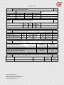
page 3 of 29
Particulars: test item vs. test requirements
Equipment mobility ..........................................:
Movable
Operating condition..........................................:
Continuous
Tested for IT power systems ......................... :
No
IT testing, phase-phase voltage (V) ............. :
N/A
Class of equipment ......................................... :
Class I
Mass of equipment (kg)...................................:
29.0kg
Protection against ingress of water .............. :
IPX0
Test case verdicts
Test case does not apply to the test object .:
N(.A)
Test item does meet the requirement .......... :
P(ass)
Test item does not meet the requirement ... :
F(ail)
Testing
Date of receipt of test item .............................:
November 25, 2009
Date(s) of performance of test ...................... :
November 26, 2009 to December 11, 2009
General remarks
The test result presented in this report relate only to the object(s) tested.
This report shall not be reproduced, except in full, without the written approval of the Issuing testing
laboratory.
”(see Enclosure #)" refers to additional information appended to the report.
"(see appended table)" refers to a table appended to the report.
Standard EN 62040:2008 is to be used in conjunction with IEC 60950-1:2005, which is referred to in this
TRF by "RD".
Model list:
Model
2000VA
Rated
input
voltage (V)
Rated
input
frequency
(Hz)
Rated
input
apparent
power(VA)
Rated
input
current (A)
Rated
output
voltage (V)
Rated
output
frequency
(Hz)
220-240
50/60
2200
7
220
50/60
5.5
220-240
50/60
3000
10
220
50/60
8.0
2200VA
3000VA
WALTEK SERVICES
Project Engineer: Grace Feng
Reference No.: WTS14S0513591S
TRF No.: EN62040_1_1A
Rated
output
current
(A)
page 4 of 29
EN 62040-1:2008
Clause
Requirement – Test
4
GENERAL CONDITIONS FOR TESTS
P
4.5
Components
P
1.5.1/RD
General
P
Comply with IEC 60950-1 or relevant
component standard
Result – Remark
All safety critical components are certified, all
components are used within their rating, plastic
materials, PCBs and wiring material are UL
listed, non-certified components were tested
according to this standard. (See appended table
1.5.1)
Verdict
P
1.5.2/RD
Evaluation and testing of components
1.5.4/RD
Transformers
1.5.5/RD
Interconnecting cables
P
1.5.6/RD
Capacitors in primary circuits ............................. :
N
1.5.7/RD
Double insulation or reinforced insulation
bridged by components
1.5.7.1/RD
General
1.5.7.2/RD
Bridging capacitors
No such capacitors
N
1.5.7.3/RD
Bridging resistors
No such resistors
N
1.5.8/RD
Components in equipment for IT power
systems
Not for IT power systems
N
4.6
Power interface
1.6.1/RD
AC power distribution systems
TN power system
P
1.6.2/RD
Input current
(see appended table 4.4)
P
1.6.4/RD
Neutral conductor
Neutral is identified in the equipment. Basic
insulation for rated voltage between earthed
parts and primary phases.
P
4.7
Marking and instructions
P
4.7.1
General
P
4.7.2
Power rating
P
Input rated voltage/range (V)...............................: 220-240
P
Input rated current/range (A)............................... : See page 3 model list
P
Input symbol for nature of supply (d.c.) ............ : AC supply
N
WALTEK SERVICES
Project Engineer: Grace Feng
Reference No.: WTS14S0513591S
TRF No.: EN62040_1_1A
P
Transformer complies with the relevant
requirements of the standard and particularly
with Annex C/RD.
No such components
P
N
N
P
page 5 of 29
EN 62040-1:2008
Clause
Requirement – Test
Result – Remark
Verdict
Input rated frequency/range (Hz)........................: 50/60
P
Output rated voltage/range (V) .......................... : 220
P
Output rated current/range (A) ...........................: See page 3 model list
P
Number of output phases (1φ - 3φ)
1φ with neutral
with/without neutral............................................... :
P
Output rated active power (W) ........................... :
N
Output rated apparent power (VA) .................... :
N
Output symbol for nature of supply (d.c.) ......... : AC supply
N
Rated frequency or rated frequency range
(Hz):
P
50/60
Max. ambient operating temperature range
40°C mentioned in user manual.
(°C).......................................................................... :
N
Manufacturer’s name or trademark or
Guangdong East Power Co., Ltd
identification mark ................................................ :
P
Type/model or type reference............................. : 2000VA, 2200VA, 3000VA
P
Symbol for Class II equipment only ...................: Class I
N
Other symbols .......................................................:
P
Certification marks ............................................... :
P
Instructions for units with automatic
No separated bypass.
bypass/maintenance bypass, additional input
a.c. supply, or external batteries, having text
"See installation instructions before
connecting to the supply" ....................................:
N
Safety instructions
P
Guidance for installation for operator and
User manual
service person ....................................................... :
P
Warning label with text "Isolate uninterruptible Pluggable type A, not permanently connected
power supply (UPS) before working on this
UPS without internal automatic backfeed
circuit"
isolation
N
4.7.4
Main voltage adjustment ......................................: No such device
N
1.7.4/RD
Supply voltage adjustment .................................. :
N
Methods and means of adjustment; reference
to installation instructions .................................... :
N
4.5.5
1.7.5/RD
Power outlets..........................................................: The maximum apparent and active power of the
standard appliance outlets is indicated on the
rear of the enclosure adjacent to the appliance
outlets. Conforming to IEC 60083.
P
4.5.6
1.7.6/RD
Fuse identification (marking, special fusing
Part of appliance inlet, or fuse holder, VDE
characteristics, cross-reference) ........................ : approved
P
4.5.7
1.7.7/RD
Wiring terminals
P
4.7.3
WALTEK SERVICES
Project Engineer: Grace Feng
Reference No.: WTS14S0513591S
TRF No.: EN62040_1_1A
page 6 of 29
EN 62040-1:2008
Clause
Requirement – Test
Result – Remark
1.7.7.1/RD
Protective earthing and bonding terminals ....... :
P
1.7.7.2/RD
Terminal for a.c. mains supply conductors .......:
N
1.7.7.3/RD
Terminals for d.c. mains supply conductors .....:
N
4.7.8
Battery terminals ...................................................: Polarity is indicated (+ and -) on the batteries.
P
4.7.9
1.7.8/RD
Controls and indicators
P
1.7.8.1/RD
Identification, location and marking ................... : Front panel
P
1.7.8.2/RD
Colours ..................................................................: Green, yellow and red of indicator are just for
function purpose.
P
1.7.8.3/RD
Symbols according to IEC 60417....................... :
N
1.7.8.4/RD
Markings using figures ....................................... :
N
4.7.10
1.7.9/RD
Isolation of multiple power sources ................... : Only one supply from the mains.
N
4.7.11
IT power systems
N
1.7.2.4/RD
IT power distribution systems
N
4.7.12
Protection in building installations
4.7.13
5.1/RD
High leakage current (mA) ..................................: Max. 0.20mA
4.7.14
1.7.10/RD
Thermostats and other regulating devices
4.7.15
1.7.2.1/RD
Language(s) .......................................................... : English
⎯
4.7.16
1.7.11/RD
Durability of markings
After rubbing test by water and petroleum spirit,
the label still easily discernible, indelible and
legible.
P
4.7.17
1.7.12/RD
Removable parts
No removable parts.
N
4.7.18
1.7.13/RD
Replaceable batteries
Irreplaceable
N
4.7.19
1.7.2.5/RD
Operator access with a tool................................. :
4.7.20
Battery
Pluggable equipment type A.
No thermostats or regulating devices used.
Verdict
N
P
N
N
Pluggable type A, UPS battery is located in
battery compartment. See page 2 Model
difference
P
Clearly legible information .................................. : On battery cell
P
Battery type ............................................................: Lead-acid
P
Nominal voltage of total battery (V) ................... : See page 2 Model difference
P
Nominal capacity of total battery (optional) ...... : See page 2 Model difference
P
Warning label ........................................................ : On battery compartment
P
WALTEK SERVICES
Project Engineer: Grace Feng
Reference No.: WTS14S0513591S
TRF No.: EN62040_1_1A
page 7 of 29
EN 62040-1:2008
Clause
Requirement – Test
Result – Remark
Verdict
Instructions ............................................................ : User manual
P
4.7.21
Installation instructions
P
5
FUNDAMENTAL DESIGN REQUIREMENTS
P
5.1
Protection against electric shock and energy hazards
--
2.1.1.2/RD
Battery compartments ......................................... : Not access to TNV circuit
N
2.1.1.4/RD
Access to hazardous voltage circuit wiring
N
2.1.1.5/RD
Energy hazards .....................................................: No energy hazard in operator area.
P
2.1.1.6/RD
Manual controls
No knob, handle, lever etc
N
5.1.1
Operator access
Only openings in sides of the enclosure. Circuits
are not touchable by test pin through the
openings.
P
Sufficient information
No such wiring
category a)
5.1.2
2.1.1.3/RD
P
category b)
Inaccessible to ELV wiring
P
Access to ELV wiring
No ELV wiring in operator accessible area.
N
Working voltage (Vpeak or Vrms); minimum
distance (mm) through insulation
⎯
5.1.3
Discharge of capacitors in the primary circuit
N
2.1.1.7/RD
Discharge of capacitors in equipment
No X-Cap.
⎯
Time-constant (s); measured voltage (V).......... :
5.1.4
Backfeed protection
N
(see appended table 5.7)
P
Description of the construction ...........................: all-pole isolation relay
⎯
5.1.5
Emergency switching (disconnect) device
N
5.2
Requirements for auxiliary circuits
P
5.2.1
2.2/RD
5.2.2
2.3/RD
5.2.3
2.4/RD
Safety extra low voltage circuits – SELV
42.4V peak or 60V d.c. are not exceeded in
SELV circuit under normal operation.
P
Telephone network voltage circuits – TNV
No TNV circuit
N
5.2.4
3.5/RD
Limited current circuits
N
Frequency (Hz)...................................................... :
⎯
Measured current (mA).........................................:
⎯
Measured voltage (V)............................................:
⎯
Measured capacitance (μF)................................. :
External signalling circuits
SELV circuit only
⎯
WALTEK SERVICES
Project Engineer: Grace Feng
Reference No.: WTS14S0513591S
TRF No.: EN62040_1_1A
P
page 8 of 29
EN 62040-1:2008
Clause
5.2.5
2.5/RD
Requirement – Test
Limited power source
Result – Remark
Verdict
5.3
Protective earthing and bonding
P
5.3.1
General
P
5.3.2
Protective earthing
P
5.3.3
Protective bonding
P
5.4
AC and d.c. power isolation
N
5.4.1
3.4/RD
General
N
5.4.2
Disconnect devices
N
5.5
Overcurrent and earth fault protection
P
5.5.1
2.7.3/RD
General
Short-circuit backup protection
P
2.7.4/RD
N
2.6/RD
Pluggable equipment type A. The building
installation is considered as providing shortcircuit backup protection.
P
Number and location of protective devices....:
One protective device current fuse is located in
Line.
P
2.7.5/RD
Protection by several devices
Only one used
P
2.7.6/RD
Warning to service personnel………………..:
No service work necessary.
N
5.5.2
Basic requirements
P
5.5.3
Battery circuit protection.......................................
P
5.5.3.1
Overcurrent and earth fault protection
Installed inside
P
with a protective device – DC Fuse
5.5.3.2
Location of protective devices
Fixing in fuse holder
P
5.5.3.3
Rating of protective devices
Comply 8.3
P
5.6
Protection of personnel – Safety interlocks
No such device
N
5.6.1
Operator protection................................................
N
5.6.2
Service person protection
N
5.6.2.1
Introduction
N
2.8/RD
WALTEK SERVICES
Project Engineer: Grace Feng
Reference No.: WTS14S0513591S
TRF No.: EN62040_1_1A
page 9 of 29
EN 62040-1:2008
Clause
Requirement – Test
Result – Remark
Verdict
5.6.2.2
Covers
N
5.6.2.3
Location and guarding of parts
N
5.6.2.4
Parts on doors
N
5.6.2.5
Component access
N
5.6.2.6
Moving parts
N
5.6.2.7
Capacitor banks
N
5.6.2.8
Internal batteries
N
5.7
Clearances, creepage distances and distances through insulation
P
2.10.1/RD
General
P
2.10.1.1/R
D
Frequency……..………………………………:
P
2.10.1.2/R
D
Pollution degrees……….……..………………:
2.10.1.3/R
D
Reduced values for functional insulation
N
2.10.1.4/R
D
Intervening unconnected conductive parts
N
2.10.1.5/R
D
Insulation with varying dimensions
N
2.10.1.6/R
D
Special separation requirements
N
2.10.1.7/R
D
Insulation in circuits generating starting
pulses
N
2.10.2/RD
Determination of working voltage
P
2.10.2.1/R
D
General
2.10.2.2/R
D
RMS working voltage
P
2.10.2.3/R
D
Peak working voltage
P
2.10.3/RD
Clearances
2.10.3.1/R
D
General
P
2.10.3.2/R
D
Mains transient voltages
P
2.10/RD
a) AC mains supply …………………………..:
b) Earthed d.c. mains supplies ………….….:
WALTEK SERVICES
Project Engineer: Grace Feng
Reference No.: WTS14S0513591S
TRF No.: EN62040_1_1A
Pollution Degree 2
(See appended table 5.7)
(See appended table 5.7)
2500Vp
P
P
P
P
N
page 10 of 29
EN 62040-1:2008
Clause
Requirement – Test
Result – Remark
Verdict
c) Unearthed d.c. mains supplies ……….….:
N
d) Battery operation ………………..…………:
N
2.10.3.3/R
D
Clearances in primary circuits
(See appended table 5.7)
2.10.3.4/R
D
Clearances in secondary circuits
N
2.10.3.5/R
D
Clearances in circuits having starting pulses
N
2.10.3.6/R
D
Transients from a.c. mains supply ……..…...:
P
2.10.3.7/R
D
Transients from d.c. mains supply ……….…:
N
2.10.3.8/R
D
Transients from telecommunication networks
and cable distribution systems ……………..:
N
2.10.3.9/R
D
Measurement of transient voltage levels
N
a) Transients from a mains supply
N
For an a.c. mains supply ……………………:
N
For a d.c. mains supply ……………………..:
N
b) Transients from a telecommunication
network
N
(See appended table 5.7)
P
2.10.4/RD
Creepage distances
P
2.10.4.1/R
D
General
P
2.10.4.2/R
D
Material group and comparative tracking
index
P
CTI tests …………………………..…………..:
Material group IIIb are assumed to be used
⎯
2.10.4.3/R
D
Minimum creepage distances
(See appended table 5.7)
P
2.10.5/RD
Solid insulation
P
2.10.5.1/R
D
General
P
2.10.5.2/R
D
Distances through insulation
P
2.10.5.3/R
D
Insulating compound as solid insulation
N
2.10.5.4/R
D
Semiconductor devices
N
2.10.5.5/R
D
Cemented joints
N
WALTEK SERVICES
Project Engineer: Grace Feng
Reference No.: WTS14S0513591S
TRF No.: EN62040_1_1A
page 11 of 29
EN 62040-1:2008
Clause
Requirement – Test
2.10.5.6/R
D
Thin sheet material - General
P
2.10.5.7/R
D
Separable thin sheet material
P
Number of layers (pcs)……………………….:
Result – Remark
2 layers
Verdict
⎯
2.10.5.8/R
D
Non-separable thin sheet material
N
2.10.5.9/R
D
Thin sheet material – standard test procedure
N
Electric strength test
⎯
Thin sheet material – alternative test
procedure
P
Electric strength test
P
2.10.5.11/
RD
Insulation in wound components
P
2.10.5.12/
RD
Wire in wound components
P
Working voltage ………………………………:
P
a) Basic insulation not under stress ………..:
N
b) Basic, supplementary, reinforced
insulation ………………………………………:
P
c) Compliance with Annex U ………………..:
P
Two wires in contact inside wound
components; angle between 45o and 90o …:
N
Wire with solvent-based enamel in wound
components
N
Electric strength test
N
Routine test
N
Additional insulation in wound components
N
Working voltage ………………………………:
N
- Basic insulation not under stress ………….:
N
- Supplementary, reinforced insulation …….:
N
2.10.6/RD
Construction of printed boards
P
2.10.6.1/R
D
Uncoated printed boards
P
2.10.6.2/R
D
Coated printed boards
N
2.10.6.3/R
D
Insulation between conductors on the same
inner surface of a printed board
N
2.10.5.10/
RD
2.10.5.13/
RD
2.10.5.14/
RD
WALTEK SERVICES
Project Engineer: Grace Feng
Reference No.: WTS14S0513591S
TRF No.: EN62040_1_1A
page 12 of 29
EN 62040-1:2008
Clause
Requirement – Test
2.10.6.4/R
D
Insulation between conductors on different
layers of a printed board
Result – Remark
Verdict
N
Distance through insulation
N
Number of insulation layers (pcs) …………..:
N
2.10.7/RD
Component external terminations
N
2.10.8/RD
Tests on coated printed boards and coated
components
N
2.10.8.1/R
D
Sample preparation and preliminary
inspection
N
2.10.8.2/R
D
Thermal conditioning
N
2.10.8.3/R
D
Electric strength test
N
2.10.8.4/R
D
Abrasion resistance test
N
2.10.9/RD
Thermal cycling
N
2.10.10/RD Test for Pollution Degree 1 environment and
insulating compound
N
2.10.11/RD Tests for semiconductor devices and
cemented joints
N
2.10.12/RD Enclosed and sealed parts:
No hermetically sealed components.
N
6
Wiring, connections and supply
P
6.1
Introduction
P
6.1.2
P
6.2
Dimensions and ratings of busbars and
insulated conductors
Connection to power
6.2.1
General provisions for connection to power
P
A non-detachable power supply cord or
P
a detachable power supply cord for an
appliance inlet
3.2.2/RD
Multiple supply connections
Single supply connection.
N
3.2.3/RD
Permanently connected equipment
Not permanently connected equipment.
N
Number of conductors, diameter of cable and
conduits (mm) …………………………...:
⎯
3.2.4/RD
Appliance inlets
P
3.2.5/RD
Power supply cords
P
3.2.5.1/RD
AC power supply cords
P
Type ………………………………………...….:
2
H05VV-F
Rated current (A), cross-sectional area (mm ), Max. 10A, 3 X 1.5mm2
AWG ………………………………….:
WALTEK SERVICES
Project Engineer: Grace Feng
Reference No.: WTS14S0513591S
TRF No.: EN62040_1_1A
P
⎯
page 13 of 29
EN 62040-1:2008
Clause
3.2.5.2/RD
Requirement – Test
Result – Remark
Verdict
DC power supply cords
N
3.2.6/RD
Cord anchorages and strain relief
P
Mass of equipment (kg), pull (N) .……..……:
100N
⎯
Longitudinal displacement (mm) ………..….:
0.02mm
⎯
3.2.7/RD
Protection against mechanical damage
P
3.2.8/RD
Cord guards
P
Diameter or minor dimension D (mm); test
mass (g) ……………………………………....:
⎯
Radius of curvature of cord (mm) ……..……:
⎯
6.2.2
Means of connection
6.3
Wiring terminals for external power conductors
Wiring terminals for connection of external
conductors
Wiring terminals
3.3/RD
3.3.1
3.3.2
Pluggable UPS type A
Only one connection
P
N
N
N
N
3.3.3
Connection of non-detachable power supply
cords
Screw terminals
3.3.4
Conductor sizes to be connected
N
⎯
3.3.5
Rated current (A), cord/cable type, crosssectional area (mm2) …………………………:
Wiring terminal sizes
⎯
3.3.6
Rated current (A), type, nominal thread
diameter (mm) ………………………………...:
Wiring terminals design
3.3.7
Grouping of wiring terminals
N
3.3.8
Stranded wire
N
7
Physical requirements
P
7.1
Enclosure
No carry current
P
7.2
4.1/RD
7.3
4.2/RD
4.2.1/RD
Stability
10°, no tip
P
Mechanical strength
250N, 5s
P
General
P
4.2.2/RD
Steady force test, 10 N
P
WALTEK SERVICES
Project Engineer: Grace Feng
Reference No.: WTS14S0513591S
TRF No.: EN62040_1_1A
N
N
N
page 14 of 29
EN 62040-1:2008
Clause
Requirement – Test
Result – Remark
Verdict
4.2.3/RD
Steady force test, 30 N
.
P
4.2.4/RD
Steady force test, 250 N
Enclosure, 5s, no damage
P
4.2.5/RD
Impact test
1.3m
Fall test
For top enclosure
P
⎯
Swing test
For right side, left side, front side and back side
⎯
4.2.6/RD
Drop test; height (mm) ……………………….:
4.2.7/RD
Stress relief test
70°C, 7 hours
P
4.2.8/RD
Cathode ray tubes
No CRT.
N
N
Picture tube separately certified …………….:
N
4.2.9/RD
High pressure lamps
No high pressure lamps.
N
4.2.10/RD
Not wall or ceiling mounted equipment.
N
7.4
Wall or ceiling mounted equipment; force
(N) ………………………………………………:
Construction details
7.4.1
Introduction
4.3.1/RD
Edges and corners
Edges and corners of the enclosure are
rounded.
P
4.3.2/RD
Handles and manual controls; force (N) ……:
No handles or manual controls.
N
4.3.3/RD
Adjustable controls
No adjustable controls.
N
4.3.4/RD
Securing of parts
P
4.3.5/RD
Connection by plugs and sockets
N
4.3.7/RD
Heating elements in earthed equipment
N
4.3.11/RD
Containers for liquids or gases
N
4.4/RD
Protection against hazardous moving parts
4.4.1/RD
General
N
4.4.2/RD
Protection in operator access areas
N
4.4.3/RD
Protection in restricted access locations
N
4.4.4/RD
Protection in service access areas
P
P
No moving part
N
7.4.2
Openings
For side opening, no hazardous and energy
hazard parts are located in projection area,
which vertically, or within a 5 degree angle from
the edges of the openings.
7.4.3
Gas concentration
See 7.6
7.4.4
Equipment movement
WALTEK SERVICES
Project Engineer: Grace Feng
Reference No.: WTS14S0513591S
TRF No.: EN62040_1_1A
N
P
P
N
page 15 of 29
EN 62040-1:2008
Clause
Requirement – Test
Result – Remark
7.5
Resistance to fire
Electrical parts not likely to ignite nearby
materials and the fire enclosures used
P
4.7.2/RD
Conditions for a fire enclosure
All components located in a fire enclosure and
metal enclosure.
P
7.6
Battery location
7.6.1
Battery location and installation
7.6.2
Accessibility and maintainability
7.6.3
7.6.4
Distance
Case insulation
7.6.5
Wiring
7.6.6
7.6.7
Electrolyte spillage
Ventilation
7.6.8
Charging voltages
P
7.7
Temperature rise
P
4.7/RD
Verdict
P
Installed inside
P
P
Ventilation
P
P
P
VRLA battery
N
P
Maximum temperatures
(see appended table 7.7)
P
4.5.2/RD
Resistance to abnormal heat
Ball pressure test (see appended table 7.7)
P
8
ELECTRICAL REQUIREMENTS AND SIMULATED ABNORMAL CONDITIONS
P
8.1
5.1.1/RD
General
P
5.1.2/RD
Equipment under test (EUT)
N
5.1.7/RD
Equipment with touch current exceeding
Max. 0.20mA
3.5 mA .................................................................... :
P
8.2
Electric strength
P
5.2.1/RD
General
(see appended table 5.7)
P
5.2.2/RD
Test procedure
(see appended table 5.7)
P
8.3
Abnormal operating and fault conditions
5.3.1/RD
Protection against overload and abnormal
operation
(see appended table 8.3)
P
5.3.2/RD
Motors
No motor
N
5.3.3/RD
Transformers
(see appended Annex C)
P
5.3.4/RD
Functional insulation...............................................
P
5.3.5/RD
Electromechanical components
P
5.3.8/RD
Compliance criteria for abnormal operating
and fault conditions
WALTEK SERVICES
Project Engineer: Grace Feng
Reference No.: WTS14S0513591S
TRF No.: EN62040_1_1A
P
(see appended table 8.3)
P
page 16 of 29
EN 62040-1:2008
Clause
Requirement – Test
Result – Remark
8.3.1
Simulation of faults
(see appended table 8.3)
8.3.2
Conditions for tests
P
9
CONNECTION TO TELECOMMUNICATION NETWORKS
N
6.1/RD
Protection of telecommunication network service persons, and users of other equipment
connected to the network, from hazards in the equipment
--
6.1.1/RD
Protection from hazardous voltages
N
6.1.2/RD
Separation of the telecommunication network from earth
N
6.1.2.1/RD
Requirements
N
Test voltage (V) .................................................... :
⎯
Current in the test circuit (mA) ......................... :
⎯
6.1.2.2/RD
Exclusions.............................................................. :
N
6.2/RD
Protection of equipment users from overvoltages on telecommunication networks
N
6.2.1/RD
Separation requirements
N
6.2.2/RD
Electric strength test procedure
N
6.2.2.1/RD
Impulse test
N
6.2.2.2/RD
Steady-state test
N
6.2.2.3/RD
Compliance criteria
N
6.3/RD
Protection of the telecommunication wiring system from overheating
N
Max. output current (A).........................................: N.A
⎯
Current limiting method........................................ : N.A
⎯
1.4.8/RD
Normal operating voltages ..................................:
N
1.4.11/RD
Power from a telecommunication network ....... :
N
2.1.1/RD
Protection in operator access areas
N
2.1.1.1/RD
Access to energized parts
N
Test by inspection ................................................ :
N
Test with test finger ..............................................:
N
Test with test pin .................................................. :
N
Test with test probe ............................................. :
N
2.1.1.2/RD
Battery compartments ......................................... :
N
2.1.3/RD
Protection in restricted access locations
N
2.3/RD
TNV circuits
N
2.3.1/RD
Limits
N
WALTEK SERVICES
Project Engineer: Grace Feng
Reference No.: WTS14S0513591S
TRF No.: EN62040_1_1A
Verdict
P
page 17 of 29
EN 62040-1:2008
Clause
Requirement – Test
Result – Remark
Verdict
Type of TNV circuits............................................. : N.A
⎯
Separation from other circuits and from
accessible parts
N
Insulation employed.............................................. : N.A
⎯
Separation from hazardous voltages
N
Insulation employed.............................................. : N.A
⎯
Connection of TNV circuits to other circuits
N
Insulation employed.............................................. : N.A
⎯
2.3.5/RD
Test for operating voltages generated
externally
N
2.6.1/RD
Protective earthing
N
2.6.5.8/RD
Reliance on telecommunication network or
cable distribution system
N
2.9.3/RD
Grade of insulation
N
2.10.3.3/R
D
Clearances in secondary circuits
N
2.10.3.4/R
D
Measurement of transient voltage levels
N
2.10.4/RD
Creepage distances
N
3.5/RD
Interconnection of equipment
N
3.5.1/RD
General requirements
N
3.5.2/RD
Types of interconnection circuits..........................
N
M/RD
ANNEX M, CRITERIA FOR TELEPHONE RINGING SIGNALS (see 2.3.1)
N
M.1/RD
Introduction
N
M.2 /RD
Method A
N
M.3/RD
Method B
N
M.3.1/RD
Ringing signal
N
2.3.2/RD
2.3.3/RD
2.3.4/RD
M.3.1.1/RD Frequency (Hz) .....................................................: N.A
⎯
M.3.1.2/RD Voltage (V) ............................................................ : N.A
⎯
M.3.1.3/RD Cadence; time (s), voltage (V) ........................... : N.A
⎯
M.3.1.4/RD Single fault current (mA)...................................... : N.A
⎯
M.3.2/RD
N
Tripping device and monitoring voltage............. :
M.3.2.1/RD Conditions for use of a tripping device or a
monitoring voltage
N
M.3.2.2/RD Tripping device
N
M.3.2.3/RD Monitoring voltage (V).......................................... :
N
WALTEK SERVICES
Project Engineer: Grace Feng
Reference No.: WTS14S0513591S
TRF No.: EN62040_1_1A
page 18 of 29
EN 62040-1:2008
Clause
Requirement – Test
A/RD
ANNEX A, TESTS FOR RESISTANCE TO HEAT AND FIRE
N
A.1/RD
Flammability test for fire enclosures of movable equipment having a total mass exceeding
18 kg, and of stationary equipment (see 4.7.3.2)
N
A.1.1/RD
Samples.................................................................. : N.A
⎯
Wall thickness (mm)............................................. : N.A
⎯
A.1.2/RD
Conditioning of samples; temperature (°C).......:
N
A.1.3/RD
Mounting of samples.............................................:
N
A.1.4/RD
Test flame (see IEC 60695-11-3)
N
Flame A, B, C or D ...............................................: N.A
⎯
Compliance criteria
N
Sample 1 burning time (s)....................................: N.A
Sample 2 burning time (s)....................................: N.A
⎯
⎯
Sample 3 burning time (s)....................................: N.A
⎯
A.2/RD
Flammability test for fire enclosures of movable equipment having a total mass not exceeding
18 kg, and for material and components located inside fire enclosures (see 4.7.3.2 and 4.7.3.4)
N
A.2.1/RD
Samples, material................................................. : Metal enclosure
⎯
Wall thickness (mm)............................................. : N.A
⎯
A.2.2/RD
Conditioning of samples
N
A.2.3/RD
Mounting of samples
N
A.2.4/RD
Test flame (see IEC 60695-11-4)
N
Flame A, B or C .................................................... : N.A
⎯
A.2.5/RD
Test procedure
N
A.2.6/RD
Compliance criteria
N
Sample 1 burning time (s)....................................: N.A
⎯
Sample 2 burning time (s)....................................: N.A
⎯
Sample 3 burning time (s)....................................: N.A
⎯
Alternative test acc. to IEC 60695-2-2, cl. 4
and 8
N
Sample 1 burning time (s)....................................: N.A
⎯
Sample 2 burning time (s)....................................: N.A
⎯
Sample 3 burning time (s)....................................: N.A
⎯
A.3/RD
Hot flaming oil test (see 4.6.2)
N
A.3.1/RD
Mounting of samples
N
A.3.2/RD
Test procedure
N
A.3.3/RD
Compliance criterion
N
A.1.6/RD
A.2.7/RD
WALTEK SERVICES
Project Engineer: Grace Feng
Reference No.: WTS14S0513591S
TRF No.: EN62040_1_1A
Result – Remark
Verdict
page 19 of 29
EN 62040-1:2008
Clause
Requirement – Test
Result – Remark
Verdict
B/RD
ANNEX B, MOTOR TESTS UNDER ABNORMAL CONDITIONS (see 4.7.2.2 and 5.3.2)
N
B.1/RD
General requirements
N
No motor
Position ...................................................................: N.A
⎯
Manufacturer ......................................................... : N.A
⎯
Type ........................................................................ : N.A
⎯
Rated values ........................................................ : N.A
⎯
B.2/RD
Test conditions
N
B.3/RD
Maximum temperatures
N
B.4/RD
Running overload test
N
B.5/RD
Locked-rotor overload test
N
Test duration (days) ............................................. : N.A
⎯
Electric strength test: test voltage (V) ................: N.A
⎯
B.6/RD
Running overload test for d.c. motors in
secondary circuits
N
B.7/RD
Locked-rotor overload test for d.c. motors in secondary circuits
N
B.7.1/RD
Test procedure
N
B.7.2/RD
Alternative test procedure; test time (h)............. : N.A
N
B.7.3/RD
Electric strength test
N
B.8/RD
Test for motors with capacitors
N
B.9/RD
Test for three-phase motors
N
B.10/RD
Test for series motors
N
Operating voltage (V) ...........................................: N.A
⎯
ANNEX C, TRANSFORMERS (see 1.5.4 and 5.3.3)
P
C/RD
Transformer is designed for operational insulation only. No safety isolation transformers
used.separating transformer is CE approved
Position ...................................................................: T1
⎯
Manufacturer ......................................................... : See table 4.3
⎯
Type ........................................................................ : See page 2 model difference
⎯
Rated values ........................................................ : Class B
⎯
Method of protection..............................................:
⎯
C.1/RD
Overload test
P
C.2/RD
Insulation
P
Protection from displacement of windings......... : Bobbin and tapes
P
WALTEK SERVICES
Project Engineer: Grace Feng
Reference No.: WTS14S0513591S
TRF No.: EN62040_1_1A
page 20 of 29
EN 62040-1:2008
Clause
Requirement – Test
D/RD
ANNEX D, MEASURING INSTRUMENTS FOR TOUCH-CURRENT TESTS (see 5.1.4)
P
D.1/RD
Measuring instrument
P
D.2/RD
Alternative measuring instrument
N
E/RD
ANNEX E, TEMPERATURE RISE OF A WINDING (see 1.4.13)
N
F/RD
ANNEX F, MEASUREMENT OF CLEARANCES AND CREEPAGE DISTANCES (see 2.10)
P
G/RD
ANNEX G, ALTERNATIVE METHOD FOR DETERMINING MINIMUM CLEARANCES
N
G.1/RD
Summary of the procedure for determining
minimum clearances
N
G.2/RD
Determination of mains transient voltage (V).... :
N
G.2.1/RD
AC mains supply
N
G.2.2/RD
DC mains supply
N
G.3/RD
Determination of telecommunication network
transient voltage (V).............................................. :
N
G.4/RD
Determination of required withstand voltage
(V).............................................................................:
N
G.5/RD
Measurement of transient levels (V)...................:
N
G.6/RD
Determination of minimum clearances...............:
N
H
ANNEX H, GUIDANCE ON PROTECTION AGAINST INGRESS OF WATER AND FOREIGN
OBJECTS (see IEC 60529)
N
J/RD
ANNEX J, TABLE OF ELECTROCHEMICAL POTENTIALS (see 2.6.5.6)
N
Metal used ............................................................. : N.A
⎯
K/RD
ANNEX K, THERMAL CONTROLS (see 1.5.3 and 5.3.7)
N
K.1/RD
Making and breaking capacity
N
K.2 /RD
Thermostat reliability; operating voltage (V)......:
N
K.3/RD
Thermostat endurance test; operating voltage
(V) .......................................................................... :
N
K.4/RD
Temperature limiter endurance; operating
voltage (V) ..............................................................:
N
K.5/RD
Thermal cut-out reliability
N
K.6/RD
Stability of operation
N
WALTEK SERVICES
Project Engineer: Grace Feng
Reference No.: WTS14S0513591S
TRF No.: EN62040_1_1A
Result – Remark
Verdict
page 21 of 29
EN 62040-1:2008
Clause
Requirement – Test
L
ANNEX L, BACKFEED PROTECTION TEST
L.1
General
L.2
Test for pluggable equipment type A or
pluggable equipment type B UPS
P
L.3
Test for permanently connected UPS
N
L.4
Single-fault conditions
P
M
ANNEX M, EXAMPLES OF REFERENCE LOAD CONDITIONS
N
M.1
General
N
M.2
Reference resistive load
N
M.3
Reference inductive-resistive load
N
M.4
Reference capacitive-resistive loads
N
M.5
Reference non-linear load
N
M.5.1
Test method
N
M.5.2
Connection of the non-linear reference load
N
N
ANNEX N, VENTILATION OF BATTERY COMPARTMENTS
N
N.1
General
N
N.2
Hydrogen concentration
N
N.3
Blocked conditions
N
N.4
Overcharge test
N
O
Guidance for disconnection of batteries during shipment
N
O.1
Applicable products
N
O.2
N
O.3
Battery disconnection
Package labelling/marking
N
O.4
Damage inspection
N
O.5
The importance of safe handling procedures
N
WALTEK SERVICES
Project Engineer: Grace Feng
Reference No.: WTS14S0513591S
TRF No.: EN62040_1_1A
Result – Remark
Verdict
P
Pluggable equipment type A
Hermetic
P
page 22 of 29
4.3
TABLE: list of critical components
P
All safety critical components should be approved, like power cord and sets,
appliance inlet, X-cap, varistor, opto coupler, relay, PCB, internal wire etc
object/part No.
manufacturer/
trademark
Front panel
enclosure, LED
cover and LCD
Lens
Plug
type/model
technical data
stan dard
mark(s) of
conformity1)
CHI MEI
PA-765
CORPORATION
80°C, V-1
UL 746
UL E56070
Ching Cheng
Wire Material
Co., Ltd.
EL-202
16A 250V~
EN 50075
VDE 40004661
Ching Cheng
Wire Material
co.,Ltd
EL210
13A 250V~
BS 1363
KM39096
Ching Cheng
Wire Material
Co.
EL-211
16A 250V~
EN 50075
VDE 40000947
Flexible cord
Shenzhen Bao
H05VV-F
Hing Electric
Wire & Cable
Manufacture Co.
Ltd.
3 x 1.5mm2
VDE 0281
VDE 103727
(alternative)
Shenzhen Bao
H05VV-F
Hing Electric
Wire & Cable
Manufacture Co.
Ltd.
3 x 1.5mm2
VDE 0281
VDE 131689
(alternative)
Ching Cheng
Wire Material
Co.
H05V V-F
3 x 1.5mm2
VDE 0281
VDE 131809
Power cord
SHENZHENG
BAOHING
ELECTRIC
WIRE AND
CABIE
MANUFACTUR
E CO.,LTD
H05VV-F
3 x 1.5mm2
VDE 0620
VDE 131689
YUHAO
ELECTRIC
MANUFACTUR
E CO.,LTD
H05VV-F
3 x 1.5mm2
VDE 0281
40027906
Appliance inlet
Dongguan
XD-102
Nanke Electronic
MFG Factory
10A 250V~
EN 60320-1
VDE 40023560
(alternative)
Rong Feng
Industrial Co.,
Ltd.
10A 250V~
EN 60320-1
VDE 40012427
WALTEK SERVICES
Project Engineer: Grace Feng
Reference No.: WTS14S0513591S
TRF No.: EN62040_1_1A
RF-2004
page 23 of 29
object/part No.
manufacturer/
trademark
type/model
technical data
stan dard
mark(s) of
conformity1)
Connector
Ching Cheng
Wire Material
Co.
EL-701
10A 250V~
--
VDE 40014003
Socket outlet 1
SS-180
Dongguan
Nanke Electronic
MFG Factory
10A 250V~
EN 60320-1
VDE 40023886
(alternative)
Rich Bay Co.,
Ltd.
R-302SN
10A 250V~
EN 60320
VDE 40006954
(alternative)
Rong Feng
Industrial Co.,
Ltd.
SS-130
10A 250V~
EN 60320
VDE 40009225
Socket outlet 2
Rich Bay Co.,
Ltd.
R-302G3
10A 250V~
VDE 0620-1
VDE 40011561
(alternative)
Rong Feng
Industrial Co.,
Ltd.
742W-3P
10A 250V~
VDE 0620-1
VDE 40009672
(alternative)
Rich Bay Co.,
Ltd.
RG-02
10A 250V~
VDE 0620-1
VDE 82796
(alternative)
Rong Feng
Industrial Co.,
Ltd.
E-08
10A 250V~
VDE 0620-1
VDE 40008508
(alternative)
RONG FENG
INDUSTRIAL
CO.
E-08D
10A 250V~
VDE 0620-1
VDE 40008508
Fuse
Suzhou
Littelfuse OVS
Ltd.
218-series
250V, 10A
EN 60127-1
VDE 40013496
Fuse holder
Littelfuse Inc.
345121
250V, 10A
EN 60127-6
VDE 40018957
Battery
SHEN ZHEN
SUNNYWAY
BATTERY
TECH CO.,LTD
UN7-12
12V, 8AH,
UL 1989
MH21285
UN8-12
12V, 7AH
GOLDED
GH-1C-12L
6A 250VAC
EN 60255
TUV
R50079239
Relay
250V, 15A
12VDC
(alternative)
(alternative)
GOLDED
GJ-1C-12L
TAIWAN SHORI S3-12/24
ELECTRIC
CO.,LTD
S7-12/24
10A 250VAC
EN 61810-1
TUV
R50164189
10A 240VAC
12/24VDC
EN 60255
TUV R9754312
12A 240VAC
EN 60255
TUV R9854359
EN 60255
TUV R9754312
12V
12/24VDC
(alternative)
SHORI
WALTEK SERVICES
Project Engineer: Grace Feng
Reference No.: WTS14S0513591S
TRF No.: EN62040_1_1A
S3-12
10A 240VAC
12VDC
page 24 of 29
object/part No.
manufacturer/
trademark
type/model
technical data
stan dard
mark(s) of
conformity1)
(alternative)
Ningbo shoi
S3-12/24
10A 240VAC
12/24VDC
EN 60255
TUV 50118517
(alternative)
SONGCHUAN
833H-1C-CDC12V/24V
10A 240VAC
12V/24DC
EN 60255
TUV R9754206
812
10A 250V,
12VDC
EN 60255
TUV50041911
845N
10A 250VAC
EN 60255
TUV R9754104
EN 60255
TUVR350006128
EN 60255
TUV R9754104
6VDC/12V
875
10A, 250VAC
12VDC
845N-2C-C
5A 250VAC
6VDC
Internal wire
EVER
BRIGHT(HK)DE
VELOPMENT
CO LTD
1015
10AWG, 600V
UL 758
UL E191230
(alternative)
ZI LI
ELECTRONIC
CO LTD
1015
10AWG, 600V,
105°C
UL 758
UL E254016
Transformer
Guangdong East
EA / BE Series Class B
Power Co.,Ltd.
--
Test with
appliance
--Thermal
protectors
Changzhou
Changhong
Tongli Electrical
Appliance Co.,
Ltd
5-15A
EN60730-1
40020906
250V~ 150°C
EN60730-2-2
(Battery used)
(alternative)
(alternative)
--Insulating
Tape
(alternative)
FOSHAN CHAN
CHENG EAGLE
TECHNOLOGY
CO LTD
KW- Series
AMT-11*,
5-15A
AMT-22*,
250V~ 150°C
17AME/
5-15A
15AME
250V~ 150°C
JINGJIANG
YAHUA
PRESSURE
SENSITIVE
GLUE CO LTD
CT, PZ
JINGJIANG
JINGYANG
INSULATING
PRODUCT CO
LTD
JY-133
YANGZHOU
WUYUE
ELECTRONIC
CO.,LTD
WALTEK SERVICES
Project Engineer: Grace Feng
Reference No.: WTS14S0513591S
TRF No.: EN62040_1_1A
UL 873
E301742
UL873
E258612
130°C
UL510
E165111
130°C
UL510
E309872
page 25 of 29
object/part No.
technical data
stan dard
mark(s) of
conformity1)
--Paper
Insulating Tape
XINFENG
GHILLIE
ELECTRICAL
JL-T4
MATERIALS CO
LTD
180°C
UL510
E326305
--Bobbin
Pinghu Meishen
Electric
apparatus
Co.,ltd
Radiflam A
AE(a) C
125°C
UL 746
E116324
ROSHOW
TECHNOLOGY
CO LTD
xUEW/130 or
QA-x/130
130°C
UL1446
E215691
ROSHOW
GROUP CO
LTD
QZ-x/130
130°C
UL1446
E215691
1015
105°C, 18AWG
UL758
E204893
Various
250V, 10A, min. -70°C
--Magnet wire
manufacturer/
trademark
ZHONG SHAN
YONG ROI
ELECTRIC
FACTORY
CO LTD
Various
--Down-lead
Switch
type/model
VDE
1
) an asterisk indicates a mark which assures the agreed level of surveillance
4.4
TABLE: electrical data (in normal conditions)
P
fuse #
Irated (A)
U (V)
Power (W)
I (A)
Ifuse (A)
condition/status
FUSE
--
198/50Hz
1875
9.54
9.54
Output load 8.0A
FUSE
--
198/60Hz
1873
9.45
9.45
Output load 8.0A
FUSE
10
220/50Hz
1860
8.70
8.70
Output load 8.0A
FUSE
10
220/60Hz
1860
8.69
8.69
Output load 8.0A
FUSE
10
240/50Hz
1850
7.65
7.65
Output load 8.0A
FUSE
10
240/60Hz
1849
7.65
7.65
Output load 8.0A
FUSE
--
254/50Hz
1806
7.18
7.18
Output load 8.0A
FUSE
--
254/60Hz
1805
7.11
7.11
Output load 8.0A
F1, F2
--
DC24V
2253
93.9
93.9
Output load 8.0A
5.1.2
TABLE: distance through insulation measurements
distance through insulation di at/of:
--
WALTEK SERVICES
Project Engineer: Grace Feng
Reference No.: WTS14S0513591S
TRF No.: EN62040_1_1A
N
Up
(V)
test volt age
(V)
required di
(mm)
di
(mm)
--
--
--
--
page 26 of 29
5.1.4
P
TABLE: Backfeed protection test
Condition
Voltage measured (V)
Comments
L-N
L-G
N-G
No load
5.9
9.2
18
--
Full load
1.5
30
27
--
5.3 and
2.4/RD
N
TABLE: limited current circuit measurement
Location
Voltage Current
(V)
(mA)
--
--
--
Freq.
(Hz)
--
Limit
(mA)
Comments
--
--
Output measured with a 2 KΩ resistor as under backup mode.
5.7 and 9
TABLE: clearance and creepage distance measurements
P
clearance cl and creepage
distance dcr at/of:
Up
(V)
U r.m.s.
(V)
required cl
(mm)
cl
(mm)
required
dcr (mm)
dcr
(mm)
Live part to metal enclosure
340
240
2.0
3.5
2.5
3.5
Live part to SELV circuit
340
240
4.0
6.5
5.0
7.0
5.7, 6, 8.2
and 9
TABLE: electric tests, impulse tests and voltage surge tests
test voltage applied between:
P
test voltage (V)
a.c. / d.c.
breakdown
Yes / No
Live parts to earthed pin of inlet
1500VAC
No
Live parts to metal enclosure
1500VAC
No
Live parts to front panel with metal foil
3000VAC
No
Live parts to SELV circuit
3000VAC
No
7.5
TABLE: resistance to fire
P
part
manufacturer of material
type of material
thickness
(mm)
flammability
class
Front panel
CHI MEI CORPORATION
PA-765
2.0
V-1
WALTEK SERVICES
Project Engineer: Grace Feng
Reference No.: WTS14S0513591S
TRF No.: EN62040_1_1A
page 27 of 29
7.5 and
8.3
TABLE: fault condition tests
P
ambient temperature (°C) ........................................ : 24.6
⎯
model/type of power supply .................................... : 3000VA
⎯
manufacturer of power supply ................................ : --
⎯
rated markings of power supply ..............................: --
⎯
com pone
nt
No.
fault
test vol tage
(V)
Output
Short circuit
240
test time
1s.
fuse
No.
fuse cur rent
(A)
FUSE 7.65 to 0
result
FUSE opened
immediately.
No hazards.
Output
Overload
240
5h.
FUSE 7.65 to 8.0 to
8.6 to 0
Unit shutdown,
recoverable after the fault
removed. Max. output
current: 9.2A, T1 winding
temperature: 96.5°C,
ambient: 26.5°C.
No hazards.
Openings
Block
240
3h.
FUSE 7.65 to 7.65
T1 winding temperature:
59.8°C, Ambient
temperature: 21.6°C, unit
normal operation.
No hazards.
D51
Short circuit
240
5h.
FUSE 7.65 to 9.3A to T1 winding temperature:
5.5
169°C, Ambient
temperature: 24.9°C,
circling operation: 15min.
20min. OFF, No hazard.
Q2 pin D
and pin G
Short circuit
Battery
mode
1s
F1,
F2
93.9 to 0
F1 & F2 opened, no
hazardous.
Q2 pin D
and pin S
Short circuit
Battery
mode
1s
F1,
F2
93.9 to 0
F1 & F2 opened, no
hazardous.
Q2 pin S
and pin G
Short circuit
Battery
mode
10min.
F1,
F2
93.9 to 0
Unit shutdown
immediately, recoverable
after the fault removed. No
hazards.
Remark:
7.7
TABLE A: maximum temperatures
P
test voltage (V) ............................
AC198
AC254
Battery discharge
⎯
tamb1 (°C) ........................................
See below
See below
See below
⎯
tamb2 (°C) ........................................
See below
See below
See below
⎯
WALTEK SERVICES
Project Engineer: Grace Feng
Reference No.: WTS14S0513591S
TRF No.: EN62040_1_1A
page 28 of 29
maximum temperature T of
part/at::
T(°C)
allowed
dTmax
(°C)
Normaliz
Normali
Normali
Measureed
Measure
Measure
ed
zed
zed
ed
ed
T(°C)
T(°C)
T(°C)
T(°C)
T(°C)
1.power cord
39.4
57.6
34.5
53.6
39.2
57.8
70
2.switch body
37.3
55.5
32.8
51.9
37.6
56.2
70
3.Lead wire of Main
transfoemer
45.1
63.3
37.7
56.8
57.6
76.2
105
64.5
82.7
55.8
74.9
73.9
92.5
63.9
82.1
54.4
73.5
63.6
82.2
6.Battery near main
transfoemer
34.6
52.8
29.6
48.7
36.4
55
Ref.
7.wire of Battery
26.5
44.7
24
43.1
44
62.6
105
8.PCB under D3
54.4
72.6
33.8
52.9
50.2
68.8
130
9.Relay J2
51.1
69.3
55.7
74.8
51.6
70.2
110
10.Relay J7
70.6
88.8
55.4
74.5
70.3
88.9
110
58.7
76.9
68
87.1
57.5
76.1
57.4
75.6
63.9
83
57.3
75.9
39
57.2
35.1
54.2
58.6
77.2
130
14.PCB under D50
63.6
81.8
55.3
74.4
65.8
84.4
130
15. Relay J6
55.7
73.9
49.8
68.9
56.3
74.9
110
16.CN5 body
52
70.2
44.2
63.3
52.2
70.8
105
17.CN3 Body
77.3
95.5
62.6
81.7
77.3
95.9
105
18.AC outlet
33.6
51.8
32
51.1
33.4
52
70
19. Metal enclosure outside
38.6
56.8
35.5
54.6
37.7
56.3
60
20. Plastic panel inside
41.3
59.5
38.8
57.9
41
59.6
80
21. Plastic panel outside
35.9
54.1
36.1
55.2
34.2
52.8
80
22.Ambient
21.8
40
20.9
40
21.4
40
--
4.Main transformer winding
5.Main transformer core
11.T1 winding
12.T1 core
13.PCB under Q4
WALTEK SERVICES
Project Engineer: Grace Feng
Reference No.: WTS14S0513591S
TRF No.: EN62040_1_1A
AC: 110
DC: 142
AC: 110
DC: 142
AC: 110
DC: 142
AC: 110
DC: 142
page 29 of 29
maximum temperature T of
part/at::
T(°C)
allowed
dTmax
(°C)
Normaliz
Normali
Normali
Measureed
Measure
Measure
ed
zed
zed
ed
ed
T(°C)
temperature T of winding:
T(°C)
R1 (Ω)
T(°C)
R2 (Ω)
T(°C)
T(°C)
T (°C)
allowed
Tmax (°C)
insulation
class
--
--
--
--
--
--
--
--
--
--
--
--
7.7
TABLE B: ball pressure test of thermoplastic parts
P
allowed impression diameter (mm) ........................ : ≤ 2 mm
⎯
part
test temperature
(°C)
impression diameter
(mm)
Bobbin of transformer
125
0.6
CN2
125
0.5
======End of Report======
WALTEK SERVICES
Project Engineer: Grace Feng
Reference No.: WTS14S0513591S
TRF No.: EN62040_1_1A
Page 1 of 6
Photo Documentation
Reference No.: WTS14S0513591S
Model: 3000VA
Photo
Photo
Waltek Services (Shenzhen) Co., Ltd.
http://www.waltek.com.cn
Page 2 of 6
Photo Documentation
Reference No.: WTS14S0513591S
Photo
Photo
Waltek Services (Shenzhen) Co., Ltd.
http://www.waltek.com.cn
Page 3 of 6
Photo Documentation
Reference No.: WTS14S0513591S
Photo
Photo
Waltek Services (Shenzhen) Co., Ltd.
http://www.waltek.com.cn
Page 4 of 6
Photo Documentation
Reference No.: WTS14S0513591S
Photo
Photo
Waltek Services (Shenzhen) Co., Ltd.
http://www.waltek.com.cn
Page 5 of 6
Photo Documentation
Reference No.: WTS14S0513591S
Photo
Photo
Waltek Services (Shenzhen) Co., Ltd.
http://www.waltek.com.cn
Page 6 of 6
Photo Documentation
Reference No.: WTS14S0513591S
Photo
Photo
Waltek Services (Shenzhen) Co., Ltd.
http://www.waltek.com.cn