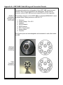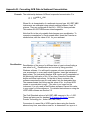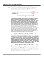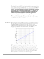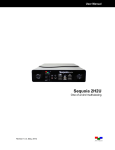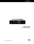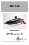
1
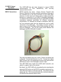
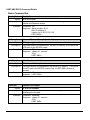
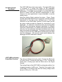
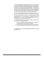
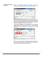
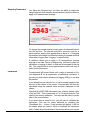
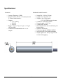
LISST-ABS Acoustic Backscatter Sensor User’s Manual Version 1.0 (July 2015) Sequoia Scientific, Inc. 2700 Richards Road Suite 107 Bellevue, WA, 98005, USA Phone: +1 425-641-0944; Fax: +1 425-643-0595 [email protected]; www.SequoiaSci.com This page intentionally left blank FOR TECHNICAL ASSISTANCE please contact your local Distributor, or Sequoia if the instrument was purchased directly from Sequoia. Please be sure to include the instrument serial number with any correspondence. A list of local Sequoia distributors can be found at our website http://www.sequoiasci.com/about/contact/distributors Sequoia Scientific, Inc. can be reached at [email protected] or by phone +1-425-641-0944. Contents SECTION 1: QUICK START ........................................................................................................... 1 SECTION 2: INSTRUCTIONS ......................................................................................................... 3 2.1 INTRODUCTION ......................................................................................................................... 3 2.2 SDI-12 OPERATIONS................................................................................................................ 4 2.3 RS232 OUTPUT OPERATIONS................................................................................................... 9 2.4 ANALOG OUTPUT OPERATIONS ............................................................................................... 14 2.5 USB OPERATIONS VIA PC SOFTWARE ..................................................................................... 16 2.6 FIELD DEPLOYMENT SUGGESTIONS ......................................................................................... 23 APPENDIX A: LISST-ABS CABLE WIRING AND CONNECTOR PINOUTS .............................. 24 APPENDIX B: CONVERTING ACB DATA TO SEDIMENT CONCENTRATION ....................... 26 APPENDIX C: HOW THE LISST-ABS WORKS ........................................................................... 27 WARRANTY .................................................................................................................................. 30 Section 1: Quick Start Intro Thank you for purchasing Sequoia's LISST-ABS acoustic sediment sensor. This Quick Start guide is intended to get you up running as quickly as possible. Detailed instructions can be found in other sections of the manual. The LISST-ABS uses acoustic backscatter to measure the concentration of particles suspended in water. It outputs the Attenuation Corrected Backscatter or ACB. The ACB can be converted to Concentration using a simple formula. For more details see Appendix B and Appendix C. The LISST-ABS is shipped ready for use. It takes just 3 easy steps to start seeing some real measurements. Step 1: Unpack box Inside the box should be the following items: LISST-ABS with protective red cap and locking cap on the connector, a 5 to 50 meter long cable with underwater connector on one end and an 8-pin plastic Molex connector on the other end, USB cable with mating Molex connector and three short pigtails with mating Molex connectors. The three cables can be used for connecting to dataloggers with screw terminals. There are separate pigtails for SDI-12, RS232, and Analog Output connections. Also included is a credit card style USB memory card with software installation files. The sensor head is covered with a protective red cap to prevent accidental impact and damage of the acoustic transceiver (white disc). Be sure to remove the protective cap before use. The instrument will not work with the cap left on. The underwater connector is also covered with a protective cap. Step 2: Install Software Step 3: Plug in USB cable and Start Program A simple program that can be used for testing the LISST-ABS is included on the USB memory card. To install the software on your computer run the LISSTABS_installer.exe program on the memory card. This will install the LISST-ABS software. This software requires the .NET 4.0 Framework. Most computers will have this framework already installed as it is used by many other programs. A message will appear if the .NET 4.0 needs to be installed. You can install .NET using the dotNetFx40_Client.exe program on the memory card. The LISST-ABS is a sensor only and must be connected to a power source. We have designed a USB cable to provide power and communicate with the instrument via one connection to a PC. Connect the long cable to the LISST-ABS and then plug in the USB cable into the PC. You should see the green LED on the LISST-ABS start to blink. Every time the LISST-ABS blinks data is being sent up the cable to the PC. If the LISST-ABS was purchased without a cable you will need to provide power to the LISST-ABS and connect the RS232 output to the PC to use the provided software. 1 You can now start the LISST-ABS software to see the values in real time. You can also use the software to store data. Below is a screen shot of the software while collecting data. More details on the operation of the software can be found in Section 2.5. The Nref value is a calibration value that is used to convert Attenuation Corrected Backscatter (ACB) to concentration in mg/L. You can determine your own Nref value based on the type of particles you will be measuring. The LISST-ABS is calibrated and adjusted at the factory using 5-10 micron particles so that the Nref for these particles will always be 1000. You may use this value for a quick approximation of concentration but proper calibration should be done to obtain the most accurate results. More information about calibrating the LISST-ABS and converting ACB to concentration can be found in Appendix B. The ACB value will update at once per second as it receives data from the LISSTABS. To store data to a file press the Create Log File button, select a location and name of a file to receive the data and then press Start Logging. Data will be stored to the file until Stop Logging is pressed. The log file contains a header with calibration constants, the Nref values and the instrument serial number. Following the header is a row for each sample containing date and time, ACB, and concentration. The Log file is a space delimited ASCII file that can be easily imported into programs such as Excel. The software has a provision to display a 30 second running average. Select this option for a smoother display of ACB and Concentration. This averaging is for the displayed value only. The values saved to the Log file are not averaged. Detailed instructions on connecting the LISST-ABS to your datalogger are covered in separate sections of this manual. For SDI-12 operations see Section 2.2. For Serial/RS232 operations see Section 2.3. For Analog Output operations see Section 2.4. 2 Section 2: Instructions 2.1 Introduction Thank you for your purchase of Sequoia's LISST-ABS acoustic backscatter sensor. The LISST-ABS is a single-point acoustic sediment sensor, designed to provide higher quality data than optical turbidity sensors. Its key advantages over optical turbidity sensors are: Superior response to particles of grain size >30 microns. Relatively flat sensitivity to particles from 30-400 microns in sizes. Greater immunity to fouling. Wide dynamic range of concentrations from 1mg/L to 70 g/L. The LISST-ABS measures the Attenuation Corrected Backscatter, ACB. This is the raw digital output of the instrument. The instrument response is logarithmic (similar to ADCP). To convert the ACB to sediment concentration, two constants are employed: a fixed constant K0, and a second constant Nref which depends on the specific type of sediment. When a user recalibrates an instrument, it is this constant Nref that is updated. For more detailed understanding of the technology, please see Appendix C. The LISST-ABS can output the ACB using three different methods, SDI-12, RS232, and analog output. All three of these outputs are available on the underwater connector on the end of the LISST-ABS. The output used is determined by how the instrument is connected to the datalogger. The LISST-ABS can be powered in two ways. For testing purposes, a special USB cable is available. When using this cable power to the instrument is provided by the USB port. When connecting to a datalogger you will need to supply a voltage between 10-18VDC. The current drain at 12V is 100 ma when actively collecting data. If the supply voltage is too low the LISST-ABS will output an ACB value of -999. When the LISST-ABS is powered up the green LED on the endcap will start to blink at about once per second. This indicated that the instrument is powered up and operating normally. When the LISST-ABS is actively sampling it will double blink (two blinks in quick succession). When idle but still powered up it will do a single blink once per second. 3 2.2 SDI-12 Operations The LISST-ABS has been designed to support SDI-12 protocol. It is compatible with SDI-12 version 1.3. This section is divided into two parts, Connecting to your datalogger and SDI-12 command summary. SDI-12 Connections SDI-12 only requires three wires. Power, Ground and Data. Appendix A includes detailed descriptions of the use of the individual pins of the 8-pin connector on the LISST-ABS. However, in most case you will be using a cable provided by Sequoia for connecting to your SDI-12 compatible datalogger. To make the connections easier we have provided different cable terminations designed specifically for different connection requirements. For example we provide a termination with only the three individual wires that are labeled and can be easily connected to the datalogger. The mating connector makes it easy to remove the long cable without disconnecting the wires from the datalogger. You can also easily switch between the datalogger and the USB cable if needed. The wires are labeled and color coded. Connect the Black wire to Ground. Connect the Red wire to +12V. Connect the Green wire to SDI-12 Data. The LISST-ABS is shipped pre-configured with an instrument address of 0. The available SDI-12 commands are described below. Following the command descriptions are some suggested best practices for using the LISST-ABS with SDI-12. 4 LISST-ABS SDI-12 Command Summary Command Name Address Query Acknowledge Active Change Address Send Identification Start Measurement Start Concurrent Measurement Send Data Continuous Measurements (Read) Start Verification Command Code Notes ?! Request address of single sensor on bus a! Request response from sensor at address a aAb! Change address of sensor at address a to b aI! Send ID string including SI address, SDI version, Manufacturers ID, sensor model, sensor Firmware version and device serial number aM! Start a measurement, returns number of seconds till sample is ready to be read. Sends service request when measurement is complete. aC! Same as Start Measurement command except does not send service request. aDb! Requests output b (0-9) from Sensor a aR! Not supported aV! Not Supported See the next page for details of SDI-12 commands. 5 LISST-ABS SDI-12 Command Details Basic Command Set ?! Address Query Syntax: ?! Description: Request address of single sensor on bus. Note: sensor must be the only sensor on the bus or multiple instruments will respond simultaneously. Example: Command: ?! Response: 0 (responds with address of sensor, in this case 0) a! Acknowledge Active Syntax: a! Description: Request response from sensor at address a. Example: Command: 0! Response: 0 aAb! (request sensor at address 0 to confirm it is active) (responds with address of sensor) Change Address Syntax: aAb! Description: Change address of sensor at address a to b Example: Command: 0A3! (request sensor at address 0 to change to address 3) Response: 3 (responds with new address of sensor) aI! Send Identification Syntax: aI! Description: Send ID string including SI address, SDI version, Manufacturers ID, sensor model, sensor Firmware version and device serial number. Example: Command: 3I! (request sensor at address 3 to send ID string Response: 313SequoiaSABS001001123456 Where: 3 = Sensor address (1 character) 13 = SDI Version compatibility (2 characters) SequoiaS = Manufacturers ID (8 characters) ABS001 = Sensor Model (6 characters) 001 = Sensor Firmware (3 characters) 123456 = Sensor Serial Number (6 characters) 6 aM! Start Measurement Syntax: aM! Description: Start a measurement, returns number of seconds till sample is ready to be read. Sends service request when measurement is complete. Example: Command: 3M! (request sensor at address 3 to make as measurement) Response: 30011 (3 is the address, 001 is # of seconds, 1 is the # of values) <after 1 second> 3 (sends address to confirm measurement is ready to be read) aC! Start Concurrent Measurement Syntax: aC! Description: Start a measurement, returns number of seconds till sample is ready to be read. Does not send service request when measurement is complete. Example: Command: 3M! (request sensor at address 3 to make as measurement) Response: 30011 (3 is the address, 001 is # of seconds, 1 is the # of values) <after 1 second, measurement is ready but no response is send> aDb! Send Data Syntax: aDb! Description: Requests output b (0-9) from Sensor a Examples: Command: 3D0! (request sensor at address 3 to send data block 0) Response: 3+123456 (responds with Attenuated Correct Backscatter, ACB) aR! Continuous Measurements Syntax: aR! Description: Not supported. The LISST-ABS is not a continuous measurement device. No data will be returned. The response to this command is below. Example: Command: 3R! (request continuous measurement) Response: 3 (responds with address of sensor) aV! Start Verification Syntax: Description: aV! Example: Not supported but the sensor will respond to the command with the response shown below. Command: 0A3! (request sensor at address 0 to change to address 3) Response: 30000 (responds with current address of sensor) 7 LISST-ABS and SDI-12 Best practices In order to obtain the most accurate results it is recommended that the LISST-ABS be powered up and allowed to sample in the automatic mode (green LED double blinking) for 30 seconds or more before issuing a Start Measurement command. This 30 second wait should be done every time power is applied. During these 30 seconds the LISST-ABS is obtaining a running average of attenuation that is used internally to compute the ACB value that is output. Shorter waits will result in noisier measurements. It is also recommended that bursts of 30 measurements or more be recorded and averaged to obtain the best results. Because of the small measurement volume of the LISST-ABS the ACB measurements can vary sample to sample as clouds of turbidity pass by. In order to obtain a representative value some averaging of these clouds should be done. For example if measurements every 15 minutes are desired we recommend the following procedure: 1) Power up the LISST-ABS 45 seconds before the beginning of the desired sample time and allow it to sample. 2) Issue the Start Measurement and Send Data commands to record 60 measurements 1 second apart. 3) Power down the LISST-ABS and wait till the next sample time. For suggestions on mounting, cleaning and maintenance please see Section 2.6. 8 2.3 RS232 Output Operations The LISST-ABS has also been designed to support RS232 communication in both transmit-only and two-way communication modes. RS232 Connections RS232 requires four wires. Power, Ground, Transmit and Receive. Appendix A includes detailed descriptions of the use of the individual pins of the 8-pin connector on the LISST-ABS. However, in most cases you will be using a cable provided by Sequoia for connecting to your RS232 compatible datalogger. To make the connections easier we have provided different cable terminations designed specifically for different connection requirements. For example we provide a termination with only the four individual wires that are labeled and can be easily connected to the datalogger. The mating connector makes it easy to remove the long cable without disconnecting the wires from the datalogger. You can also easily switch between the datalogger and the USB cable if needed. The wires are labeled and color coded. Connect the Black wire to Ground. Connect the Red wire to +12V. Connect the Yellow ABS Transmit wire to the datalogger Receive input and the Blue ABS Receive wire to the Datalogger transmit output. The LISST-ABS uses a baud rate of 9600 with 8 data bits, one stop bit, no parity, and no flow control. By default, the LISST-ABS will automatically start outputting the computed ACB values out the RS232 connection upon power up. The values are output at once per second. The values are one integer per line. The line is terminated with a linefeed character. We call this the Automatic Mode output. 9 The simplest method of collecting RS232 data is to capture and store the values being returned from the LISST-ABS as it is output. As described below in the recommended sampling procedure the instrument should be allow to output for 30 seconds after power up before measurements are recorded. There are also a set of commands that can be sent to the LISSTABS to give more control of the flow of data. The available RS232 commands are described below. The commands are not case sensitive and there are multiple command codes for the same command function. Following the command descriptions are some suggested best practices for using the LISST-ABS with RS232. LISST-ABS RS-232 Command Summary Command Name Display Status Take and Transmit Sample (and hold) Command Code Notes DS Display the Current Status of the Status instrument including instrument serial number and firmware version GS Instrument makes a measurement, stores GetSample it in temporary memory, and outputs the results to the RS-232 output. Take Sample and hold it HS HoldSample Instrument makes a measurement and stores it in temporary memory. The results are NOT sent to the RS-232 output. Transmits the last sample collected by the issuing of a GS or HS command that was stored in temporary memory. Transmit last sample SL SendLast Return to Automatic Mode Return AutoMode Exit Returns the LISST-ABS to automatic mode where results are output to the RS232 every 1 second Help HE Help Displays a list of commands available with brief descriptions See the next page for details of the RS232 commands. 10 LISST-ABS RS232 Command Details Basic Command Set DisplayStatus Display Status Syntax: DS or ds or status Description: Display the Current Status of the instrument including instrument serial number and firmware version Example: Command: DS Response: Serial number: 6014 SDI-12 address: 0 Version Jul 8 2015 15:01:34 LISST-ABS> GetSample Take and Transmit Sample (and hold) Syntax: GS or gs or getsample Description: Instrument makes a measurement, stores it in memory, and outputs the ACB value to the RS-232 output. Example: Command: GS Response: <delay of 1 second> 1234 LISST-ABS> HoldSample Take Sample and hold it Syntax: HS or hs or holdsample Description: Instrument makes a measurement and stores it in memory. The results are NOT sent to the RS-232 output. Only a LISST-ABS> prompt is returned Example: Command: HS Response: LISST-ABS> SendLast Transmit last sample Syntax: SL or sl or sendlast Description: Transmits the last sample collected by the issuing of a GetSample or HoldSample command. Example: Command: SendLast Response: <delay of 1 second> 1234 LISST-ABS> 11 Return Return to Automatic Mode Syntax: GO or go or return or exit Description: Returns the LISST-ABS to automatic mode where results are output to the RS232 every 1 second Example: Command: Exit Response: <delay of 1 second> 1234 <delay of 1 second> 1234 … Help Display Help Syntax: HE or help Description: Displays a list of commands available with brief descriptions Example: Command: help Response: **** LISST-ABS help menu **** DS or Status Display status. GS or GetSample Take a sample and return the ACB. HE or Help This menu. HS or HoldSample Take a sample and hold the ACB (nothing returned). AutoMode, Exit, Return to 1hz sampling. Press <cr> three times to or Return halt sampling. SL or ShowLast Display the previous sample taken by GS or HS. Commands are not case sensitive. LISST-ABS> 12 LISST-ABS and RS232 Best practices In order to obtain the most accurate results it is recommended that the LISST-ABS be powered up and allowed to sample in the automatic mode (green LED double blinking) for 30 seconds or more before issuing a Start Measurement command. This 30 second wait should be done every time power is applied. During these 30 seconds the LISST-ABS is obtaining a running average of attenuation that is used internally to compute the ACB value that is output. Shorter waits will result in noisier measurements. It is also recommended that bursts of 30 measurements or more be recorded and averaged to obtain the best results. Because of the small measurement volume of the LISST-ABS the ACB measurements can be vary sample to sample as clouds of turbidity pass by. In order to obtain a representative value some averaging of these clouds should be done. For example if measurements every 15 minutes are desired we recommend the following procedure: 1) Power up the LISST-ABS 45 seconds before the beginning of the desired sample time and allow it to sample. 2) Option 1: Start recording the values being output by the LISSTABS to record 60 measurements 1 second apart. Option 2: Issue GetSample commands to record 60 measurements 1 second apart. 3) Power down the LISST-ABS and wait till the next sample time. For suggestions on mounting, cleaning and maintenance please see Section 2.6. 13 2.4 Analog Output Operations The LISST-ABS has a third output option. The digital ACB value is converted to a voltage and output on the underwater connector. This voltage can be recorded and converted back to ACB values. It is highly recommended to use either SDI-12 or RS232 to obtain the most accurate measurements of ACB. However, for some applications it may be desirable to use the analog output. Using the Analog Output requires four wires. Power, Power Ground, Signal and Signal Ground. Appendix A includes detailed descriptions of the use of the individual pins of the 8-pin connector on the LISST-ABS. However, in most cases you will be using a cable provided by Sequoia for connecting to your datalogger. To make the connections easier we have provided different cable terminations designed specifically for different connection requirements. For example we provide a termination with only the four individual wires that are labeled and can be easily connected to the datalogger. The mating connector makes it easy to remove the long cable without disconnecting the wires from the datalogger. You can also easily switch between the datalogger and the USB cable if needed. LISST-ABS and Analog Output Best Practices The wires are labeled and color coded. Connect the Black wire to Power Ground. Connect the Red wire to +12V. Connect the Green wire to Analog input and the White wire to the Signal Ground. The Analog Output of the LISST-ABS is configured such that 1mv of output is equal to 1 ACB count. Therefore if the output of the LISST-ABS is 1234 ACB counts then the analog voltage would be set to 1234 mV or 1.234 volts. 14 In order to obtain the most accurate results it is recommended that the LISST-ABS be powered up and allowed to sample in the automatic mode (green LED double blinking) for 30 seconds or more before recording the analog voltage output. This 30 second wait should be done every time power is applied. During these 30 seconds the LISST-ABS is obtaining a running average of attenuation that is used internally to compute the ACB value that is output. Shorter waits will result in noisier measurements. It is also recommended that bursts of 30 measurements or more be recorded and averaged to obtain the best results. Because of the small measurement volume of the LISST-ABS the ACB measurements can be vary sample to sample as clouds of turbidity pass by. In order to obtain a representative value some averaging of these clouds should be done. For example if measurements every 15 minutes are desired we recommend the following procedure: 1) Power up the LISST-ABS 45 seconds before the beginning of the desired sample time and allow it to sample. 2) Record 60 measurements of the analog voltage 1 second apart. 3) Power down the LISST-ABS and wait till the next sample time. For suggestions on mounting, cleaning and maintenance please see Section 2.6. 15 2.5 USB Operations via PC software Installation The LISST-ABS is shipped with a simple windows application that allows for viewing and logging of ACB data. The application also provides a feature that allows for easy calibration of the LISST-ABS. The installer and related software files are located in the Software folder on your instruments ship disk. Open the installer by double clicking on ‘LISST-ABS_installer.exe.’ The software requires that you have windows .NET framework 4.0 or later installed on your computer. You can determine if the framework is installed on your computer by simply running the LISST-ABS installer. If the framework is missing, a warning message will appear: Should you receive this message, return to the ship disk and run the ‘dotNetFx40_Client.exe’ installer. This will install the .NET framework on your computer. Once that is completed, relaunch the ‘LISST-ABS_installer.exe’ and follow the installation instructions. The installer will place a LISST-ABS shortcut on your start menu as well as your desktop. USB Drivers Before launching the LISST-ABS software plug the USB cable into your computer. If the computer has an internet connection it should automatically install the correct drivers. A notification will appear on the screen if the drivers are being installed automatically. If the drivers are not installed, go back to the ship disk and run ‘CDM USB Driver.exe.’ Follow the on screen instructions to install the drivers. 16 Automatic Instrument Detection When the LISST-ABS software is launched, it will begin searching for the instrument on the ports of your computer. Ensure the instrument is connected to the computer via the USB cable. Within a few seconds the software will find the instrument and begin displaying ACB values. The instrument serial number will also be displayed at the center of the screen. If the Sequoia USB cable is not available you can still use the software via any RS232 connection to the PC. You will need to power the instrument separately. See Appendix A for wiring instructions. Should you have more than one ABS instrument plugged into your computer, the software will interface with the first instrument it finds while searching your computers ports. 17 Sampling Parameters Just below the Sequoia logo, you have the ability to adjust the sample interval (time between measurements) and the option to apply a 30 measurement average. To change the sample interval, simply type in the desired interval into the text box. The interval must be in seconds, must be a whole number, and must be greater than or equal to 1. Changing this number will change how often the display is updated and how often data is logged (see ‘Logging,’ covered below). A checkbox allows you to apply a 30 measurement running average to the data. This is for display only, and has no effect on calibration or logging of data (i.e. data are not averaged in the log file). This can provide a more representative value with only a quick look at the screen. Calibration Concentration will remain blank until a value is entered for N ref (see Appendix B for an explanation of calibration constants). If you are only interested in viewing and logging ACB, you can skip this section. If you already have a value for Nref, it can be simply typed into the text box at the center of the screen. Concentration will then be calculated using the entered value and then displayed on the screen. Note that all LISST-ABS instruments use a factory default value of Nref as 1000. This corresponds to 5 to 10 micron Arizona Test used for the factory calibration. You may use this value to get an idea of the concentration. If you don’t have a value for Nref, you will have to calibrate the instrument. This can be easily achieved by pressing the ‘Recalibrate Nref…’ button. A new window will appear. It will list the simple steps you need to follow to calibrate the instrument (left). A check box at the bottom of the window allows you to save 18 a calibration text file that contains the 100 ACB measurements that were used to calculate the Nref. You may wish to save this file for your records, but it is not required for the calibration to proceed. After following the calibration steps the software will begin collecting 100 measurements (If you elected to save a calibration file, you will be prompted for a location to save the file). The sample number will count down from 100. Once completed, a new Nref will be calculated and entered into the text box. This Nref value will be saved in the software between sessions (i.e. next time you open the software, Nref will be filled in automatically). Concentration will now be displayed alongside ACB: 19 If you elected to save the raw ACB values, a text file will be saved at the location you specified before starting the calibration. It will contain a header with calibration information, followed by the 100 ACB measurements used to calculate the new Nref. Should you need to remind yourself where an Nref value came from, you can click the info button located next to the Nref textbox. Logging Before data can be saved, a log file must be created. Start by clicking on the ‘Create Log File…’ button. A browser will open that will allow you to specify a location and name for the log file. Once that is complete, the location of the log file will be displayed at the bottom of the screen (note: the location displayed at the bottom of the screen can also be edited by hand, which is handy for incrementing file names). 20 Press the start logging button to begin saving data to the log file. The number of measurements saved to the log file will be displayed in the lower right of the screen. The log file header contains calibration information. The header is followed by four columns of data: date, time, ACB, and concentration (mg/L). Errors/Disconnection Should there be a power interruption or momentary disconnection, the LISST-ABS software will automatically reconnect when the power or connection is reestablished. If the disconnection occurs while logging data, the logging will pause and resume automatically when the instrument is reconnected. Should one of the two error codes be produced by the ABS, the error code will be displayed and a brief description of the problem will be shown. An ACB value of -999 means low power supply voltage, instrument could not operate. A value of -888 implies obstruction within sample volume, or the second sample volume is at a boundary (see Appendix C). In either case, this error is triggered when backscatter from the second range cell is stronger than the first. 21 22 2.6 Field Deployment Suggestions The mounting and orientation of the LISST-ABS is similar to that of optical backscatter and turbidity sensor. The suggestions below may help when determining how to mount or orientate the LISST-ABS The LISST-ABS measures backscatter from two cells at approximately 5 and 10 cm from the sensor head. The two locations are used to measure the attenuation that is used in the internal computation of ACB. Mounting Orientation For reduced drag, mount the LISST-ABS horizontally facing into a flow. In this orientation, it may be placed very close to a boundary (e.g. a river bed), limited only by considerations of bed scour. The instrument may also be mounted vertically. To avoid interference from bottom reflection, the sensor head must be at least 15 cm above the hard bottom. The computation of ACB assumes that the concentration is similar between the range cells. If there is a strong vertical gradient causing significant differences between them the ACB will not be accurate. The sensor housing is made of plastic. DO NOT apply excessive force while mounting. The diameter of the main body is just under 2 inches. There are many different types of clamps available for this diameter. BioFouling reduction Biofouling can be a problem for any sensor deployed in the water. Even though the LISST-ABS is more tolerant to biofouling it is still recommended to use some anti-fouling procedures to reduce the chance of fouling effecting the measurements. Do not apply anti-fouling paint directly to the transducer face as it will affect the instrument performance. 23 Appendix A: LISST-ABS Cable Wiring and Connector Pinouts This appendix details the configuration of the LISST-ABS connectors and cables so that it can be connected to the dataloggers. We will start at connector on the LISST-ABS and work toward the end of the long cable. Details of The endcap connector on the LISST-ABS is an Impulse MCBH8-M-P, wired Underwater as shown below. Mating connector is MCIL8-F-S. connector on LISST-ABS 1. Common 2. Supply voltage, 10 to 18 V 3. Common 4. RS232 transmit 5. RS232 receive 6. SDI-12 input/output 7. Analog output 8. Common The Common pins are interchangeable and connected to each other inside the ABS. Bulkhead Connector numbering Cable Connector Numbering 24 Sequoia offers cables for the LISST-ABS in lengths from 5 to 50 meters. These cables include an underwater connector is spliced to a longer cable which is terminated with a white plastic Molex connector. When purchasing the long cable multiple mating cables are provided for different datalogger connections. There are pigtail ends for SDI-12 connections, RS232 connections, Analog Output connections, and a USB Cable for use with a PC. The table below shows the details of the wiring of the different cables. MCBH8M on ABS Pin 1 2 3 4 5 6 7 8 Function Common V+ (10 to 18V) Common RS232 transmit RS232 receive SDI-12 data Analog out Common Sequoia long cable RS232 pigtail SDI-12 pigtail Analog pigtail Wire color White Red Yellow Blue Black Green shield Wire color Black Red Yellow Blue - Wire color Black Red Green - Wire color Black Red Green White Wire color Black White Red Green Blue Grey Yellow Orange The long cable is terminated with a Molex Mini-Fit Jr Female connector (Molex # 0039012081 with Molex # 0039000431 pins). The mating pigtail cables use a male connector with a latch (Molex 0039012080 with Molex #0039000073 sockets). Both connector have labels for the pin numbering molded into the plastic body of the connector. The pin number is also shown above. 25 Appendix B: Converting ACB Data to Sediment Concentration Formula The relationship between ACB and suspended concentration C is C = 10(ACB-Nref)/500 Where Nref is characteristic of a sediment size and type. All LISST-ABS instruments are calibrated using natural particles between 5 and 10 microns. They are configured so that Nref = 1000 for these particles. This makes all LISST-ABS sensor interchangeable. Note that Nref is the only variable that changes upon recalibration. To compute concentration, in Excel spread sheet, insert the Formula as shown below, with the value of Nref for your sediment. Recalibration Recalibration of the sensor for different size or type involves finding a new value for Nref. Recalibration can be done by using provided Windows software. You will need to prepare a known concentration of your suspension, in a very well-mixed chamber. Insert the instrument, apply power. The instrument displays ACB counts and Concentration at the previously held value of Nref. At any time, Press the Recalibrate button and follow instructions. At the end of about a minute, the software computes the new Nref and loads it into the designated box. The measurements that follow use this value of Nref to convert ACB counts to concentration in mg/L. This value is not saved on the instrument. It is only used in the Windows software. Record this value in your notes for future reference. For detailed instructions on using the LISST-ABS software see Section 2.5. The Gold Standard values of all LISST-ABS sensors is: Nref = 1,000. These are factory set for standard 5-10 micron AC Dusts (source: Powder Technology Inc., Arden Hills, MN, USA). Conversion of a saved file of ACB's can be done using the formula above at any time, even after a new Nref is determined. See Appendix C. 26 Appendix C: How the LISST-ABS works Basics The LISST-Acoustic Backscatter Sensor, LISST-ABS operates in a manner similar to radar. A short pulse of high-frequency sound is transmitted by a ceramic transducer (see Figure). The pulse travels outward, and its location at any time is at a distance equal to the product of speed of sound in water c, and time t after transmission, ct. Particles in the pulse (called 'cell', 'range cell', ' range bin', or 'sample volume') scatter sound in all directions. Some of this sound travels backward toward the transducer. This scattered sound takes the same amount of time t to reach back to the transmitter. This is the backscatter signal. The total time for this signal out and back is 2t. Thus the signal sensed at time 2t after pulse transmission corresponds to scattering from a range cell a distance ct from the transmitter. This is the essence of acoustic backscatter. The strength of the backscatter pressure P at the transducer from a range R = ct is related to the outgoing pressure pulse Po, the geometric spreading G(R), and attenuation by the combination of water and sediments. It is helpful now to consider the signal via the sonar equation: log10[P/Po] = -G(R) - 2[w + s]R + log10 () + N(R) (1) This equation shows the weakening of the signal due to geometric spreading G(R), attenuation by absorption by water (w) and sediment (s), and a noise floor N(R). The signal of interest is the scattering by particles, . The LISST-ABS actually measures the backscatter signal from two range cells located at ct1 and ct2 from the transducer, so that it can compensate for attenuation by particles in water. To understand, consider the difference of two signals such as above, but with assumption of equal concentration. By difference, we have: log10 [P1] - log10 [P2] = [-G(R) 2w R] - sR (2) This shows that the difference in signals from two range bins is equal to the geometric spreading factor, and attenuation. The attenuation term is usually very small for LISST-ABS until sediment concentration becomes high, >1g/L. [we ignore noise floor, it is small]. Thus the two-point backscatter determines the quantity in square bracket. Any increase in the difference determines water attenuation term. 27 Knowing the terms in Eq.(2), we simply project the measurement to a small distance from the transducer, i.e. at R ~0 in Eq.(1), yielding the concentration term log10 (). With a little more arithmetic, that is ACB. In short, the combined geometrical and water attenuation are measured once and are fixed. [Temperature related changes in w are small and applied subsequently.] The sediment attenuation is measured by the change in the difference between two range cells. And then, the measurement is projected to the transducer to get ACB. This is a simplified explanation. The precise description of the computations is to be published separately. Here, we simply note that near-field effect has been considered. Recalibration The relationship between ACB and sediment concentration is shown in the figure below for 5-10 micron AC dust. Note that this is a log-linear relationship. ACB counts depend on log10(C). The slope of the calibration line Ko is fixed by electronics. The offset at 1mg/L (where log10(1) =0) is called Nref.. For all instruments, Nref =1000. A change in sediment grain-size or other properties does not change Ko. Only Nref is recalibrated, so that all sediment calibration lines are parallel. To find the new calibration factor, we recommend using our provided Windows software. Prepare a mixture in a well-mixed chamber [Use of Sequoia's mixing chamber is strongly recommended]. Insert the instrument tip at the surface. Be sure to leave 15 cm gap between sensor and chamber bottom. Press the Recalibrate button. After completion in ~1 minutes, a new value will appear. 28 Specifications: Technical: • • • • • Mechanical and Electrical: • • • Acoustic Frequency: 8 MHz Sample Volume: 10 dia x 15 L (mm) (located 5.5 cm in front of sensor) Outputs: • 0-5 V analog • SDI-12 • RS-232 Range: 1 mg/L to 70 g/L (7 m) or <50 g/L (200 m sand) Calibration: Recommended with in-situ samples • • • • • • • • 29 Sensor Dia.: 2.00 in (5.08 cm) Length: 13.25 in (33.65 cm) Weight: 1 lb. (0.5 Kg) in air; 0.5 lb. (0.22Kg) buoyant in water. Transducer: 10mm dia, ceramic External supply : 10-18 Vdc Current drain: 100 mA Max. Depth: 100 m (check with factory for deeper rating) Material: ABS Plastic Connector: Impulse MCBH-8- MP-SS Power on LED: Green, blink on update Sample update rate: 1Hz [average of 1000 measurements(pings)] Warranty STATEMENT OF LIMITED WARRANTY AND LIABILITY This Statement of Limited Warranty applies to all Sequoia Scientific, Inc. (“SEQUOIA”) products ("Products"). Any additional or different terms, including any terms in any purchase order, will be of no effect unless agreed to in writing by an authorized representative of SEQUOIA as reflected in a written SEQUOIA quotation. 1. Limited Warranty SEQUOIA warrants that upon delivery by SEQUOIA (a) the Products will be free from defects in materials and workmanship, (b) the Products will perform substantially in accordance with SEQUOIA's applicable specifications, and (c) any Products (or components or parts thereof) that are manufactured by SEQUOIA do not infringe any U.S. patent or copyright. 2. Correction of Non-Compliance If, during the twenty-four months after installation, or thirty months after delivery, whichever comes first (the “Warranty Period”), any Product does not comply with the warranties set forth in 1(a) and 1(b) above, SEQUOIA will, at its option, either (a) repair the Product, (b) replace the Product, or (c) refund the purchase price paid by Customer to SEQUOIA for the Product; provided that Customer gives SEQUOIA written notice of the noncompliance within the Warranty Period and ships the Product to SEQUOIA within one month after the end of the Warranty Period. As to any Product repaired or replaced by SEQUOIA, the Warranty Period will end upon the later of the end of the original Warranty Period or 90 days after SEQUOIA's delivery of the repaired or replacement Product to Customer. Any Product, component, part or other item replaced by SEQUOIA becomes the property of SEQUOIA. SEQUOIA may use refurbished components in the repair of Products supplied hereunder. SEQUOIA's warranties shall be void and not apply if the Product has been subjected to misuse or alteration or repaired by a party not approved by SEQUOIA or the serial number on a product (if applicable) has been altered or defaced. SEQUOIA shall not be liable for normal wear and tear (such as replacement of consumables), nor for defects or failure caused by maintenance, misuse, negligence or failure resulting from non-compliance with SEQUOIA’s specifications, operating or maintenance manuals. 3. Infringement Indemnification If any Product does not comply with the warranty set forth in 1(c) above, SEQUOIA will defend and indemnify Customer against any third-party claim asserted in any proceeding against Customer based on this noncompliance; provided that Customer gives SEQUOIA prompt written notice of the claim, SEQUOIA has exclusive control over the defense and settlement of the claim, Customer provides such assistance as SEQUOIA may request in connection with the defense and settlement of the claim (in which event SEQUOIA will reimburse the reasonable out-of-pocket costs incurred by Customer to provide such assistance), Customer does not settle the claim without the prior written consent of SEQUOIA and, upon SEQUOIA's request, Customer returns the Non-Complying Product to SEQUOIA for modification, replacement or a refund of the purchase price paid by Customer to SEQUOIA for the Non-Complying Product, less a reasonable allowance for Customer's use prior to return. 4. Exclusive Warranties THE WARRANTIES SET FORTH IN PARAGRAPH 1 ABOVE ARE EXCLUSIVE AND IN LIEU OF ALL OTHER WARRANTIES, EXPRESS OR IMPLIED. SEQUOIA DISCLAIMS ANY AND ALL WARRANTIES, EXPRESS OR IMPLIED (INCLUDING, BUT NOT LIMITED TO, ANY IMPLIED WARRANTY OF MERCHANTABILITY OR FITNESS FOR A PARTICULAR PURPOSE, AND ANY IMPLIED WARRANTY ARISING FROM COURSE OF PERFORMANCE, COURSE OF DEALING, OR USAGE OF TRADE) OTHER THAN THOSE SPECIFICALLY SET FORTH IN PARAGRAPH 1. 5. Exclusive Remedies CUSTOMER'S RIGHTS AND REMEDIES SET FORTH IN PARAGRAPHS 2 AND 3 ABOVE ARE EXCLUSIVE AND IN LIEU OF ANY AND ALL OTHER RIGHTS AND REMEDIES FOR ANY BREACH OF OR OTHER FAILURE TO COMPLY WITH ANY WARRANTY WITH REGARD TO ANY PRODUCT. 30 6. No Consequential Damages SEQUOIA will not be liable for any indirect, incidental, special or consequential damages, any cover, or any loss of revenue, profit, data or use. 7. Limitations of Liability SEQUOIA's liability (whether in contract, tort, or otherwise; and notwithstanding any fault, negligence, strict liability or product liability) with regard to any Product (including, but not limited to, any breach of or default by SEQUOIA) will in no event exceed the purchase price paid by Customer to SEQUOIA for such Product. Further, SEQUOIA will not be liable for, or be in breach of or default on account of, any delay or failure to perform as a result of any cause, condition or circumstance beyond SEQUOIA's reasonable control. 8. Indemnification by Customer Customer acknowledges that the Products are designed and manufactured for use in non-critical, monitoring situations. If Customer chooses to purchase a Product or Products for use in applications that could result in damages in excess of the price of the Product if the Product does not operate properly or otherwise fails, Customer acknowledges and agrees that it is Customer’s responsibility to provide for redundancy and/or other safety or back-up measures sufficient to assure that failure of a Product(s) will not cause such damages. Customer agrees that it will defend and hold SEQUOIA harmless from any and all claims and costs (including but not limited to attorney’s fees and other costs of defense against such claims) in excess of the price of the Products arising directly or indirectly from such Customer’s use of the Products. Such indemnification is a critical part of the consideration being provided by Customer (over and above the price paid for the Product(s)) for the right to use the Products for such purposes and Customer shall not use a Product or Products for such purposes if it is unwilling or unable to provide such indemnification. 9. Statute of Limitations Customer will not commence any action based on breach of warranty with respect to any Product more than 30 months after SEQUOIA's delivery of such Product. 10. Software The Products may include or be delivered with certain computer programs, databases or other software that is proprietary to SEQUOIA. SEQUOIA hereby grants Customer a nonexclusive license to use such software solely for the purpose of operating Products. Customer will not: use any such software for any other purpose; modify, adapt, translate, or create derivative works based on any such software; or disassemble, decompile or reverse engineer any such software. No title to or ownership of any software or intellectual property rights are transferred to Customer. 11. U.S. Government Restricted Rights Notice All software, data, technical information, and written materials provided by SEQUOIA are provided with restricted rights. Use, duplication, or disclosure by the government is subject to restrictions as set forth in subparagraph (c)(1)(ii) of the Rights in Technical Data and Computer Software clause at 48 C.F.R. § 252.227-7013 or in subparagraph (c)(2) of the Commercial Computer Software-Restricted Rights clause at 48 C.F.R. § 52.227-19, as applicable. Portions of these items may be unpublished. SEQUOIA reserves all rights under applicable copyright laws. 12. Controlling Document In the event of any conflict or inconsistency between any provision of this Statement of Limited Warranty and any other provision of the Order, the provision of this Statement of Limited Warranty will control. 13. Controlling Law This Statement of Limited Warranty will be governed by the laws of the State of Washington without reference to its rules relating to choice of law for the purpose of applying another jurisdiction’s law. The U.N. Convention on Contracts for the International Sale of Goods will not apply. 31