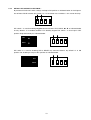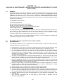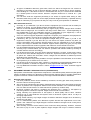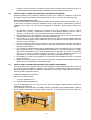
1
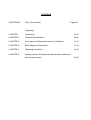
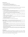
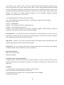
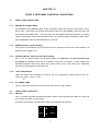
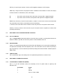
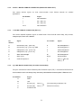
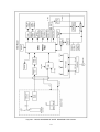
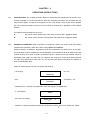
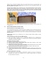
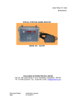
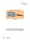
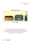
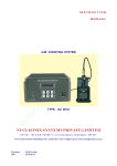
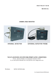
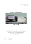
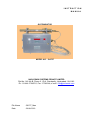
INSTRUCTION MANUAL GATE MONITOR MODEL NO. : GA727 NUCLEONIX SYSTEMS PRIVATE LIMITED Plot No: 162 A & B, Phase II, I.D.A. Cherlapally, Hyderabad - 500 051. Ph : 91-040-27263701, Fax : 27262146, e-mail : [email protected] File Name : GA727_Man Date : 20-08-2013 CONTENTS CHAPTER No. Title of the contents Page No. Unpacking CHAPTER I Introduction 01-02 CHAPTER II Technical Specifications 03-06 CHAPTER III Front panel and Side panel controls / indications 07-10 CHAPTER IV Block diagram & Description 11-13 CHAPTER V Operating Instructions 14-19 CHAPTER IV Availing services for Equipment Maintenance/ calibration and warranty clause 20-23 UNPACKING The Gate Monitor Type: GA727 has been thoroughly tested and is dispatched in ready to install & operate condition. However, on unpacking and prior to operation, it is advisable to check visually and make sure that there is no visible damage caused in transit. Also checkup the items (instrument / accessories / cables etc.) physically by verifying with the packing list contents for correct types & quantities. Any discrepancy if found, may please be communicated by email to Head, Customer support division. Typical packed carton may contain (a) Electronic unit GA727 (b) Wall mounting bracket or floor mounting stand (c) Wall mounting clamp for external detector probe. (d) External detector probe (e) A.C. mains cord (f) 10 meter multi core cable to connect detector probe to main GA unit. Pictures of these items are given below. Gate monitor GA727 Detector wall Mounting clamp Electronic Unit wall mounting bracket A.C. Mains cord Connecting cable between Electronic Unit and ext. detector probe Floor mounting stand For Electronic Unit If any damage to the instrument is observed, do not switch ON the unit and report the matter immediately to: Head CSD Customer Support Division Nucleonix Systems Private Limited Plot No: 162 A & B, PHASE II, I.D.A. Cherlapally, Hyderabad - 500 051. Ph : 91-040-27263701/30918055, FAX : 91-040-27262146, e-mail :[email protected] In all correspondence regarding the instrument, please mention the type, serial number of the unit, date of supply etc., of the unit. CHAPTER – I INTRODUCTION Gate monitor Type: GA727, manufactured & supplied by NUCLEONIX SYSTEMS is designed primarily to monitor low levels of gamma radiation. It uses state-of-art electronic devices (latest) including microcontroller with associated peripheral devices and other discrete ICs & components. Use of these devices makes it compact & highly reliable. Powerful embedded code adds-up and enhances its performance and gives extra advantage from the angle of fault diagnostics, programmable features & measurement of dose rate & data communication under networked environment. This unit is primarily designed to indicate dose rates in the measuring unit selected & produces audio / visual alarms, if the dose rate exceeds preset value. By default the unit is set to be in mR/hr & the range is (0-10000 R/hr). This Gate Monitor GA727 unit will be useful for monitoring Low Gamma dose rate levels in working areas of Radio Isotope Laboratories, Radiology departments, Medical & Industrial Radiological installations apart from its usefulness in Atomic Power Stations, radiochemical plants, waste immobilization plants etc., With power ON, initialization of hardware, peripheral devices, seven segment LED display, 16x2 LCD display / timers, counter etc, takes place. Followed by this, dose rate calculation takes place in the selected unit such as mR/hr. Additionally, hardware & fault diagnostic check will be carried out. Display updating will take place every 4 sec. Time constant (TC) for doserate will be computed depending upon the detector output count rate. Gate monitor GA727 indicates dose rate digitally on 6x7 segment LED display as well a 16x2 LCD display. There are two visual annunciator lamp windows GREEN & RED for NORMAL & ACTIVE conditions respectively. The ACTIVE window flashes once the dose rate alarm occurs and in normal condition the NORMAL window glows. The user interface is through a front panel keypad comprising of EHT, PROG, INC, DEC, ACK & RESET keys. PROG key shows up different menu options on successive operation. INC, DEC are used to scroll / select various PROG options. ACK and RESET are used for acknowledging and resetting the unit during Active alarm condition. The unit has user selectable options like Alarm preset level, Baud rate (for serial communication), Reset mode (auto or manual) and other system settings. Pressing EHT key displays the current EHT value in the detector probe. For external detector arrangement, the detector probe can be connected to main Electronic unit by a multicore cable with both end connector arrangement upto a maximum of 30 meters or even more. 1 Some important features of this unit are: Microcontroller based design with extensive use of peripheral devices & serial bus interface has been employed. Dose rate range covered is (0 - 10000) R/hr by default, with option of selection of other three 'units' namely µSv/hr, & CPM. Auto ranging & auto TC selection in the range of 30 sec to 0.5 sec depending upon detector count rate. Large size 6x7 segment LED indication for dose rate is provided. Designed using LND GM tube type GM132E or its equivalent. Large size WINDOWS for NORMAL & ACTIVE alarm condition. 16x2 LCD dot matrix display for visualization & setting of various options. 2 CHAPTER – II TECHNICAL SPECIFICATIONS Radiation to be detected : Gamma Radiation. Range : 1 10000 R/hr 0.01 100.00 Sv/hr 0- 50000 CPM Range and Unit are configurable Detector : High sensitivity energy compensated Halogen -quenched G. M. Tube GM132E or equivalent having a sensitivity of 160 cps / mR/hr Accuracy : +/ - 10% Full scale. EHT : 400 V to 700 V DC adjustable (Typical 500V) Display : Auto-ranging direct reading, 6 digit 7 segment LED display and 16x2 LCD display. 6x7 segment display is used for display of doserate information and hardware status information & 16x2 LCD display is used for visualization of preset alarm and other parameters. Overload : Senses overload above 200% of fullscale and upto 1 R/h & indicates on display “OL” Over-range : Senses if the radiation field being measured has exceeded the measurement range of the instrument and upto 200% of the instrument and displays “OFl” Recorder output : 4 to 20 mA, with 600 ohm load. Recorder output stability : a. Non-linearity : Max = 0.025% of Span b. Offset current (Io=4mA) : Max = 0.0005% of Span / C c. Span Error (Io=20mA) :Max = 0.005% of Span / C Time Constant Normal (Slow) : First reading on Power ON within 5 secs. : 30 sec to 0.5 sec automatically varying inversely with the radiation level. Abrupt detection Calibration Accuracy : Update the current reading within 2 sec and return to normal mode. : +/- 10% through out the range. 3 Instrument “ON” Indication : Large Area Green LED Lamp. This will indicate the Normal condition also. Alarm range : 1 9999 R/hr. 0.01 99.99 Sv/hr 1-50000 CPM The alarm level setting will be carried out through front panel keypad / handheld configurator / PC. Front panel keypad is provided with DIP switch de-activation. Alarm Indication : a) Red (LED) flashing large area window display b) Loud alternating audio tone (Dual frequency tone) Alarm annunciation scheme : As tabulated below : Alarm annunciation scheme : As tabulated below : Parameter Status Visual indication (Red LED) Audio Normal OFF OFF Abnormal Flashing ON On Acknowledgement Steady Red OFF Back to Normal Steady Red OFF Reset on abnormal Steady Red OFF Reset on normal OFF OFF Instrument Controls : a) Acknowledgement switch for muting audio b) Reset switch for resetting the Alarm indication and alarm relay. c) Power ON/OFF switch (This is inside the cabinet) with Power ON indication Instrument Fault indication : EHT failure : Visual alarm with flashing red LED indication & “Eht” message on display Detector failure : Visual alarm with flashing red LED & “d-FL” message on display. Microprocessor / microcontroller failure : Visual alarm with flashing green lamp. Fault indications shall be cleared automatically if normal status is resumed. Detector Housing: a. The detector is located external to the Monitor. b. It is housed in a suitable, air-tight SS shell with built-in pre-amplifier to drive upto 50 mtrs long cable. c. The instrument is provided with 10 mtr cable between detector and the monitor. d. The detector housing qualify minimum industrial protection Class IP-54. e. The monitor have clamp on the top for fixing the detector assembly. f. A separate mounting bracket for detector housing is provided. g. Provision to connect the detector with short cable also is available. 4 Monitor Enclosure: a. Vapour-tight , rugged & elegant. b. The door is provided with lock and key arrangement. c. The enclosure qualify minimum industrial protection Class IP-54. d. Decorative with visual aesthetics, prominent alarm display and good readability. Mounting: Detector housing is mounted using clamps on top of the monitor. The monitor is wall mountable type. Brackets for the monitor & detector housing are supplied along with the equipment. Remote /External Console: a. 4 - 20 mA linear proportional to full scale display output. Current output is able to drive load of 600 ohms. Output circuitry shall be able to drive 200 mtrs.of twisted pair of wires. b. Two sets of potential free contacts of Alarm relay (Change over). Contact rating 3 Amp at 250 VAC. The relay is energized on normal condition and de-energised under alarm condition. c. Remote alarm acknowledgement and reset signals for the field instruments (Normally open contact). d. Indication of instrument fault condition (detector, EHT and LV supplies failure), over range & overflow conditions by up-scale 4-20 mA. (22.5 mA) e. All these signals are terminated on a 17 pin socket (Allied Connectors). The corresponding mating plug with 5 mtr cable is supplied with the monitor. f. RJ 45 connector for Ethernet port g. RS-485 serial port (optional). This is in parallel with D-type connectors. Computer Interface : The monitor shall have a Ethernet 10/100 Mbps port for interfacing with a remote IBM PC-compatible computer. The features supported by Ethernet port are given below. • The PC and the monitor shall operate in a host-slave configuration and the software protocol will be MODBUS/TCP. • The PC as the host shall give commands and send queries. The monitor will carry out various functions in response to the queries. • The firmware of the monitor shall be able to send the instrument data like instrument ID, instrument type, input range, display range, alarm settings, alarm status, current reading, diagnostic status of EHT/GM tube etc. to the Host PC on demand. • The firmware shall be able to receive commands from Host PC and carry out the setting of different parameters like instrument ID, instrument type, input range, display range, alarm settings, Ack, Reset, instrument address etc. RS485 (Optional) The monitor have a RS-485 Serial Communication port for interfacing with a IBM PC- compatible computer. The PC and the monitor operate in a host-slave configuration in a multi-drop network through this interface. The PC as the host give commands and send queries. The monitor carry out the various functions as per the required information in response to the queries. 5 The firmware of the monitor is able to send the instrument data like Instrument ID, Instrument type, Input range, Display range, alarm settings, alarm status, current reading, diagnostic status of EHT/GM tube etc. to the Host PC on demand. The firmware is able to receive commands from Host PC and carry out the setting of different parameters like Instrument ID, Instrument type, Input range, Display range, alarm settings, Ack, Reset, EHT setting, instrument address etc. The configuration settings is password protected and the password is user defined. The detailed specifications for the interface are as follows :Type : RS-485 Multidrop Serial Communication Port, Half Duplex Bi-directional communication. Character Format : ASCII Protocol : MODBUS/RTU Bit Rate : User configurable to 9600 or 19200 bits per sec. Address : User configurable from 0 to 255. Connector : 9-pin D-type connectors (2 connectors connected in parallel for daisy chaining a number of instruments). The mating connectors with cover shall be supplied. Self Diagnostics : The monitor has built-in self diagnostics. On being powered it will perform tests to ensure that all components and sub systems are functioning properly. It will check for the Power supplies, High Voltage Supply, Detector and Counting electronics. Input Power : 230VAC +/-10%, 50Hz, single phase supply. Power ON/OFF switch is provided with a neon indicator. Spike suppressor and line filter are also provided. Environment: The unit enclosure and detector assembly comply with IP-54. Electronic units withstand cumulative radiation dose of 10000 Rad. (30 years of operation). Mechanical Enclosure: Size: 357H x 410W x 140D Weight: 8.5kg approx Instrument Trolley: (offered separately) A suitable stand for fixing area monitor will be supplied optionally. This will be made of MS and will be provided with brackets for mounting the instrument. This stand is manufactured to qualify Seismic test (IEEE-344). OPTIONS : (1) 16 bit resolution current loop (4-20mA) instead of 14 bit resolution. (2) Log scale O/P for 4-20mA instead of 4-20 linear O/P (3) 3.5” QVGA color TFT display in lieu of 7 segment LED & 16x2 LCD display (4) RS485 serial interface 6 CHAPTER - III FRONT & SIDE PANEL CONTROLS / INDICATIONS 3.1 FRONT PANEL INDICATIONS 3.1.1. NORMAL & ACTIVE LAMPS The NORMAL lamp (GREEN) glows during acquisition mode until the dose rate exceeds alarm, preset value. Once dose rate exceeds alarm preset value, then the NORMAL lamp turns OFF and the ACTIVE lamp (RED) blinks. Once the dose rate falls below the preset level, then (i) if Reset mode is AUTO then it comes back to Normal mode. (ii) if RESET mode is MANUAL, then it comes back to NORMAL mode only after RESET key is pressed. 3.1.2. DOSERATE [6x7 segment display] This gives the visual display of the current dose rate in acquisition mode in the ‘unit’ selected. By default it shows in R/hr unit. 3.1.3. STATUS DISPLAY: [16x2 LCD dot-matrix display] This is a 16 X 2 alpha numeric LCD dot-matrix display and responds to all the commands from the keypad and displays dose rate in acquisition mode with “A” blinking. It also displays the different parameters like Preset alarm level, Reset mode, Audio status, Baud rate, Calibration adjustment, Audio frequency adjustment etc., 3.1.4 ‘UNIT’ INDICATIONS There are FOUR LED indications to show-up, the ‘unit’ selected for measurement by the user. These are ‘ R/hr’, ‘Sv/hr’, & ‘cpm’. 3.1.5 A.C. MAINS LAMP This is a neon lamp indication which glows when the unit is in ‘ON’ condition. 3,2 FRONT PANEL CONTROLS : 3.2.1 KEYPAD This is a tuctile keypad with electrical connections taken to the main PCB. The follow fig. shown the key functions provided, on this keypad. (Functions of these keys are explained in detail under operating instructions) EHT ACK PROG RESET 7 EHT key: On pressing this button it shows-up EHT applied to detector, on LED display PROG key: Using this button, all program functions available can be checked. Of course the display of these functions is indicated on (16x2) LCD display. - key can be used to increase the value at the cursor position / toggle the option. - key can be used to shift the cursor position from right to left / toggle the option. RESET key: Reset key is used to reset the alarm, condition. In auto reset once dose rate falls below the preset alarm level, audio & visual alarms reset, automatically. In ‘manual’ reset mode alarm active condition is reset only when the user presses ‘Reset’ button. ACK key: This key is used to ‘ACK’ the alarm, by the user (this function is explained, in detail, under operating instructions) 3.3. SIDE PANEL AND CHASSIS MOUNTED CONTROLS 3.3.1. ON / OFF SWITCH This is a toggle switch (mounted inside the unit on the chassis) which is used to power ON the unit. When the switch is put 'ON', the AC mains power is made available to the unit. 3.3.2. AUDIO BUZZER There is an audio buzzer provided on left side of the main Electronic unit. Under alarm condition this unit produces loud beeps with dual frequency tone. The audio alarm can be turned off (muted) by pressing ACK key. It can be made OFF permanently through the AUDIO ALARM - ON/OFF option in PROG menu. 3.3.3 FUSE HOLDER This is provided on right side control panel. Fuse protection provided has a 750 mA fuse. 3.4. SIDE PANEL CONNECTOR DETAILS 3.4.1. 3 PIN MS MALE CONNECTOR (MAINS) This is a 3 pin MS connector (male) for connecting to the A.C power cable, to power-up the Electronic unit. Pin Number Signal 1 Live 2 Neutral 3 Chassis / Earth / GND 8 3.4.2. 9 PIN D - MALE & FEMALE CONNECTOR (RS485 IN & RS845 OUT): This carries RS485 signals for data communication under RS485 network for SCADA applications. 3.4.3. Pin Number Signal 1 No Connection 2 RS - 485 (“A”) 3 RS - 485 (“B”) 4 to 9 No Connection 17 PIN MS FEMALE CONNECTOR (EXT I/O): This carries required important signals to control room. These include current loop, relay contact, voltage output, alarm Ack & RESET. Pin Signal Pin number Signal A Current O/P (+ve). [I out +ve] H N/C Changeover II B Current O/P (-ve). [I out -ve]- GND J N/O Changeover II C Voltage O/P (+ve). [V out +ve] K COM Changeover I D Voltage O/P (-ve). [V out -ve] L N/C Changeover I E Alarm Acknowledge M N/O Changeover I F Alarm reset N,R,P No Connection G COM Changeover II S Data (+) T Data (-) number 3.4.4. RS-485 5 pin MS MALE CONNECTOR (TO DETECTOR PROBE): This gets connected to external detector probe. Detector output (TTL) is converted to RS485 format & transmitted to main unit through long connecting cable between detector probe & Electronic unit. Pin Number Signal A GND B +5V C RS-485 (“A”) Data (+) (For connecting to detector side D RS-485 (“B”) Data (-) RS485 Transceiver) E Fraction of HV 9 5 pin MS connector Male connector (To Detector Probe) 9 pin D - Female Connector (RS485 IN & RS845 OUT) 9 pin D - Male Connector (RS485 IN & RS845 OUT) 17 pin MS Female connector (EXT I/O) 3 pin MS Male connector (Mains) Fuse holder Fig : Side panel connectors Detector Detector probe with 5 pin MS connector (male) 3.5 ACCESSORIES The following are the additional mechanical accessories provided along with the main unit. Wall mounting detector probe clamp Seismic qualified floor mounting stand for Electronic Unit 10 Wall mounting bracket for Electronic Unit CHAPTER – IV BLOCK DIAGRAM & DESCRIPTION Gate monitor GA727 is shown in block diagram on the next page. It mainly consists of two parts. (a) Detector probe with associated electronics & (b) Main measuring unit with majority of µC based functional electronics & embedded code. 4.1 DETECTOR PROBE ELECTRONICS This consists of energy compensated detector 7807 or its equivalent, with pulse processing electronics, TTL to RS485 converter and +500V, HV module for detector biasing. Detector output signals generated from RS485 transmitter chip are fed to main PCB through 5 pin I/O cable, connected to the Electronic unit. These signals are received by RS485 receiver chip & counted by a 6 digit BCD counter in the main PCB. The output of this counter is read by micro-controller continuously. The +5V power supply, required for HV module and pulse processing SIL chip, generated on main board, is taken through a 5 pin I/O cable, to this detector probe unit. 4.2 MAIN PCB CIRCUITS Low voltage supplies +5V, +18V, +24V & +5V ISO are generated through mains transformer, secondary & three terminal regulator chips. All these supplies are used internally to power-up various circuits, for their functionality. A four channel ADC reads fraction of HV & LVs & reports to micro-controller under program control to indicate HV & LV failures if any to the user. User interface to GA727 is through keypad command buttons EHT, PROG, INC, DEC, ACK & RESET. These keys enable the user to configure & select various programmable options such as alarm set point, unit of measurement, baud rate for communication, calibration factor & many more such functions etc., EEPROM serves as a memory device to store all the configured parameters including instrument ID etc., There are two visual displays provided (a) 16x2 LCD display & (b) 6 digit 7 segment LED display, driven by multiplexed display driver. LCD display indicates all programmable functions & their values while programming & it also indicates, dose rate, in acquisition mode (normal situation). ½ “ LED display indicates dose rate in the selected unit (such as mR/hr or Sv/hr or cps or cpm) The other interfaces to micro-controller include; (a) Buzzer driver circuit along with buzzer for audio alarm which produces 90 db output at 1 meter distance. 11 (b) Visual alarms (ACTIVE & NORMAL) cluster LED array GREEN & RED with their driver circuit to indicate alarm & normal condition. (c) There are unit indication LEDs to show-up unit selected, out of four options i.e., mR/hr, Sv/hr or cps or cpm (d) 14 bit precision DAC converts doserate into (0 – 5V) signals. This in turn is fed to a voltage to current convert chip, to obtain current loop, output (4 to 20mA) from the Gate Monitor. (e) A relay driver with relay PCB provides two sets of change over contacts for external use. This relay is in energized condition in NORMAL condition of Gate monitor & in de-energized state in ACTIVE condition. (f) For data transmission from Gate monitor to SCADA, an RS485 interface has been built using TXD & RXD pins of micro-controller. This facilitates area gamma monitors RS485 networking for data communication. These RS485 signals have been brought out on a pair of 9 pin Dconnectors (male / female) for RS485 daisy chain connection of devices. Additionally these signals are made available on 17 pin also. Most of the interfacing devices or circuits or peripheral chips are connected to micro-controller through I2C bus, or ports or I/O expanders etc., for interfacing. 12 Drg A 01.: BLOCK DIAGRAM OF GATE MONITOR TYPE: GA727 13 CHAPTER – V OPERATING INSTRUCTIONS 5.1. INTRODUCTION: This chapter illustrates details on configuring and operating the instrument, for a desired installation in a plant environment. Basically, operating instructions are illustrated with the help of menu options / responses that appear on LCD / LED displays. Each of the menus facilitate the user to choose function/ value to be set or entered as desired for its operation, at the installed location. An important note (to follow) for the user is 5.2 - key can be used to increase the value at the cursor position / toggle the option. - key can be used to shift the cursor position from right to left / toggle the option. POWER ON CONDITION: When instrument is switched on, initially, the audio visual observations noticed till the indications shown are stable is called power on condition. When the power is switched on, the following audio visual indications are noticed. First, to start with, one audio beep is heard. Followed by this the following visual indications will be lit. Red cluster LED window will flash for a while and goes off. Followed by this, normal cluster LED window will be lit, additionally other LED’s for” dose rate unit” indication will all glow for a while and default selected unit LED will lit permanently. The status of LCD and large LED display with power on condition is given in the following table. When we switch ON the unit, the LCD display will show-up LCD display GATE for 1 sec MONITOR then NUCLEONIX for another 1 sec SYSTEMS Followed by this, unit goes into acquisition mode and displays the following on ½ “ LED display And 16x2 LCD display XXXX XXXX R/hr A Character ‘A’ blinks indicating that dose rate acquisition is ON & R/hr unit is default unit, stored. 14 5.3 ENTER PASSWORD Now to program & configure the unit for desired functions or to change preset values, user has to go through ‘PROG’ button / key. Different menus will appear as follows. On pressing ‘PROG’ key first time unit will display menu as follows, prompting the user to enter factory set four digit PASSWORD ENTER ^ PASSWORD : XXXX To enter the password use or keys. If the password entered is correct then it will go to next option of the menu as given below & facilitates the user to enter ‘ALARM SET POINT’. 5.4 ALARM SET POINT GA727 will show the current default alarm set value of 50 R/hr. If user wants he can change to another value, by or keys. ALARM SET POINT : XXXXX Once alarm set point is programmed, user can Press ‘PROG’ key once again to go to next option in the menu i.e., given below. 5.5 RESET MODE RESET AUTO/MANU MODE ‘RESET’ option user can either set it as AUTO or MANU (manual). In manual reset, user has to press the RESET button to bring back the unit into normal mode, once the dose rate falls below the alarm set point. In auto mode, once the dose rate falls below the alarm set point, the unit automatically returns to normal mode and the alarm condition is turned off. AUTO/MANU option can be selected by or keys. Default setting is = Manual Once RESET MODE, option is selected user can now press ‘PROG’ button to go to next menu option i.e ‘Audio Status’ 5.6 AUDIO STATUS There are FOUR options, for the user and any one of the options can be selected by or keys. D = TONE / TONE 2 / TONE 1 /OFF These four options include dual tone, Tone2, Tone1 & off mode. Once this option is selected then press ‘PROG’ key to go to next menu option ‘BAUD RATE’. Default setting is = D TONE 15 5.7 BAUD RATE Baud rate is to be selected for data communication in a networked environment for RS485 communication. There are two options as indicated in LCD display. BAUD RATE 9600/19200 One can select any of the two options for baud rate by using by or keys. Having done that, user can go to next option by pressing ‘PROG’ key. The next option that appears in LCD display is hardware check. Default setting is = 9600 5.8 HARDWARE CHECK Hardware check can be performed by or keys. HW. CHK This checks LV supplies & EHT. If these are found to be alright, display prompts with an indication as ‘OK’. Following this indication user can now go to the next option in menu by again pressing ‘PROG’ key. This prompts a menu as ‘calibration factor’. 5.9 CALIBRATION FACTOR This is a feature provided in the design, to facilitate the user to set calibration factor such that the calibration accuracy is within specified range. It may so happen that detector to detector sensitivity may slightly vary & by setting this value suitably one can get desired calibration accuracy. Range provided is 0.75 to 1.25 for calibration factor. CALIB. XX.XX FACTOR By default it is set to 1.00 default. If user wants to go through calibration again, after changing the calibration factor, he may do so. Having set this & upon pressing ‘PROG’ key, the next menu option that appears is SET UNIT. 5.10 SET UNIT (setting of Engineering unit) Here there are four options that appear in the LCD display as shown below SET UNIT R/hr / Sv/hr / cpm User can select any one of the four units as required by his plant / facility. However by default, R/hr unit is set at factory. Selection is by or keys. The next menu option that will appear, on selection of ‘PROG’ key after this above function set, is ‘DEVICE ADDRESS’. Default setting is = R/hr 16 5.11 DEVICE ADDRESS This is a three character numerical value. This is RS485 address of the instrument limits 0 - 255 Default settings is = 000 DEVICE ADDRESS XXX User can select desired three digit address (ID) of the instrument. Use or keys to load this value. Having completed this task press ‘PROG’ button for the next menu i.e., ‘AUTO ACK’ 5.12 AUTO ACKNOWLEDGE This is a selection option for alarm Ack AUTO ACK ON/OFF (5 min) By or one can select or toggle this option. If it is selected as ON, after 5 minutes automatically alarm is acknowledged & audio alarm goes ‘MUTE’. However visual alarm remains active. Followed by this the next menu option is ‘MAX SCALE’ which is prompted on pressing ‘PROG’ button. Default setting is = OFF 5.13 MAX. SCALE Depending on the unit chosen i.e., R/hr or Sv/hr or cpm, the maximum permissible scales are 10000, 100.00 & 50000 respectively. User can choose any value upto a max of this upper limit & a value above the minimum value. Any value chosen out of these boundaries will be ignored, (at the time of saving settings) and default values will be loaded. In the display, chosen unit will appear & appropriate max value desired can be entered by the user. Similar is the case for other units such as Sv/hr, or cpm. After selection of max. scale, user can now select ‘PROG’ button to go to next menu option, as follows. Default setting is = 10000 R/hr MAX R/hr (4-20mA) 5.14 MIN. SCALE XXX.XX MIN R/hr (4-20mA) XXX.XX Depending on the scale selected initially, appropriate unit (i.e typical R/hr) appears in the display. User cannot enter the min. scale value which is equal or above the max. scale value selected. Any value not meeting boundary conditions will be ignored while saving the settings & default value will be loaded. Similar if the engineering unit changed then the min. & max. scales are tabulated as follows, 17 Engineering Unit Max. scale (4-20mA) Min. scale (4-20mA) R/hr 10000 00000 Sv/hr 100.00 000.00 50000 00000 CPM Followed by this, on pressing ‘PRG’ button, the following menu appears ‘load default settings? Note : Max. & Min. scales are primarily for current loop scaling, for control room operation. Also, in the visual LED display also the same scales are set. Any value exceeding this max. scale will show as over range, as per definition in the LED display However in the lower LCD display it continues to show dose rate, as per actual value. 5.15 Default setting is = 0000 R/hr LOAD DEFAULT SETTINGS In case the user wants to retain default settings, he can skip all the previous menus & select this menu & chose option by pressing or key for default settings. LOAD DEFAULT SETTINGS? Followed by this selection & upon pressing ‘PROG’ key one would see the menu as given below. 5.16 MODIFY PASSWORD MODIFY PASSWORD YES/NO If user wants to change the pass word, he can do so by or key. Select no option to retain same password. Having done that, finally we have completed all the ‘PROG’ button functions & are ready to save settings. The next menu that appear as given below. 5.17 SAVE SETTINGS SAVE ? SETTINGS Use or keys to save all the above settings. These are permanently stored in the EEPROM and will be recalled at next powering on of the instrument. Having configured for required settings unit is now ready for operation, once settings are saved unit automatically gets into operation mode and starts acquiring dose rates and indicates in the display visually. 18 5.18. DETAILS OF DIP SWITCH SETTINGS : By default all FOUR DIP switch settings are kept in ON position as indicated below in the diagram. Out off these FOUR switches only Switch 1 & 2 is have been used. Switches 3 & 4 are not wired up. ON 1 2 3 4 DIP switch 1 is used for enabling keypad command buttons EHT, PROG, & as indicated below and by default it is in enabled condition. For disabling keypad DIP switch 1 is to be kept in OFF position. Diagrammatically it is indicated below. EHT PROG ON 1 2 3 4 DIP switch 2 is used for disabling ACK & RESET key command buttons. By default it is in ON position. For disabling it is kept in OFF position as indicated below. ON ACK RESET 1 19 2 3 4 CHAPTER – VI AVAILING OF MAINTENANCE/ CALIBRATION SERVICES AND WARRANTY CLAUSE (with in India) 6.1 GENERAL As per the warranty clause of the company, we provide one year warranty during which period we provide free service at our works. Hence in case of any mal-function in our instruments, you are requested to send the unit back to our works by RPP/COURIER/SPEED POST PARCEL/GATI/XPS/door delivery. We shall arrange immediate rectification/replacement within two weeks from the date of receipt of the equipment at our place. Please note that the equipment will be serviced at our works only. The equipment is to be sent to: The Servicing Department NUCLEONIX SYSTEMS PRIVATE LIMITED Plot No: 162 A & B, PHASE II, I.D.A. Cherlapally, Hyderabad - 500 051Ph: 040-27263701/329145448/32918055 E-mail: [email protected] www.nucleonix.com For all the Radiation monitoring equipment, detectors built-in or external probes will not have oneyear warranty, but only inspection warranty at the time of supply is provided. Since detectors will / may have fragile glass construction, we do not provide warranty. In case of failure of these components, Nucleonix will supply detector replacement at cost-cost price. Note: In respect of all types of portable radiation monitors, it may be necessary to checkup and recalibrate the equipment once a year at our works. 6.2 (a) EQUIPMENT REPAIRS / SERVICING POLICY (WITH IN INDIA) During Warrantee The following procedure is to be followed by the customers with in India for availing services/ repairing facility during warrantee period. Equipments are to be sent to our works for availing free repair services during warrantee, after the customer receives approval from the customer support division, by sending an e-mail. For all equipments, costing less than 6.0 lakhs one year warrantee & free service is offered, when the equipments are sent to our works only. For larger systems such as installed systems, networked systems, specialized systems, costing more than 6.0 lakhs during one year warrantee, free service is offered at site. Field service Engineer will be deputed subject to warrantee terms & conditions. This does not include personal computer related problems, for which local computer service provider of the PC vendor is to be contacted. Also for software related problems online support will be provided. Software support doesn't include cleaning of virus problems etc. When the equipments are sent to our works for warrantee services, they are to be properly packed with adequate cushion to prevent any transportation damages. Nucleonix Systems is not responsible for damages or loss during transportation. Packing / Freight charge is to be borne by customer when he sends the equipment to our works. However when we return after servicing packing will be Nucleonix responsibility & Freight charges will be to your account. Only services are free. Please indicate in your correspondence equipment model & serial number. All the equipments are to be sent to our works only on door delivery basis. For Door Delivery Transportation contact XPS/GATI cargo in your city / town or a reliable courier service to pick the consignment from your place. For their nearest local address & phone no's look into their websites. Transit insurance if the customer feels is necessary it is to be covered. Nucleonix Systems will not receive the equipments sent by other modes of transportation, such as Rail/Road. After servicing, equipments will be sent back by same mode of transport such as XPS/GATI/COURIER/RPP. 20 All types of Radiation detectors, glass ware, PMTs etc which are fragile are not covered in warrantee, if the failure is due to physical damage, external or internal due to shock, dropping, miss-handling etc. If the failure is due to a natural fault then only it is covered under warrantee for a limited period of three months. However complete electronics is covered for 1 year warrantee. You can also send the equipment personally to our works for repairs either during or after warrantee, after fixing up with our service dept (Customer Support Division). If possible we may repair on same day or your person can stay for a day or two & get it repaired & or calibrated. (b) After warrantee Services On expiry of 1yr warrantee if you like to send the equipment (low cost less than 6.0 lakhs) for repairs to our works, you may please observe the following procedure. Send an e-mail with details mentioning that you agree to pay service charges which includes: Basic service charges per unit / module in the range of Rs: 2500 to Rs : 10,000 depending on the sophistication of the unit calibration charges ( if applicable for your equipment) + cost of components + packing charges + Return Freight charges @ actual. Once our customer support department responds & requests you to despatch the equipment to our works for repairs, you may do so by following the steps given below. Followed by this you can send the equipment straight away if it is within 5 yrs old. If the equipment is beyond 5 yrs old, then also you can send it for repairs, however only after you receive confirmation from Customer Support Division, that it is repairable & is not an obsolete model. If the design is obsolete then customer support division (CSD) may give you 'buy back' offer to replace with new model or upgrade it with electronic circuit boards & enclosure. For all installed equipments costing above Rs: 6.0 lakhs which are larger in size & for which field servicing only is recommended, you can obtain a quotation with relevant details by sending an e-mail & avail the services accordingly. For all field servicing jobs, since we need to depute engineers, it is likely, to take time & also it will cost more which includes Engineer's TA & DA etc., apart from basic service charges + cost of spares etc. Please note that basic service charges will be different for different products depending upon sophistication. Also in some cases it may not be possible to fix-up the problems in the field itself, in such cases we may advise you to send them to our works. For all jobs to be serviced in the field, customer is requested to provide adequate details on the nature of problems, to enable our engineer to come prepared with adequate spares. For any additional information send an e-mail to [email protected], Atten: Customer support division. 6.3 EQUIPMENT REPAIRS / SERVICING POLICY (FOR EXPORTS) Equipments, manufactured & exported are subjected to a well defined quality assurance (QA) plan & Factory acceptance tests (FAT). Nucleonix systems has the following policy to provide maintenance support to overseas customers either directly or through international dealers / distributors. (a) During & after warranty: For minor problems, which can be handled by customers, servicing tips have been provided in the user manual / servicing manual. Also most of the equipments have built-in fault diagnostic features which will indicate to the user nature of problem in the equipment. Based on the visual indication in the instrument Display, user can take corrective action or contact Nucleonix systems by email for help. Nucleonix systems will guide in localizing the defective part / module or sub-system by interacting with the customer if required. Skype will be used for communication. During warranty free replacement of sub-system or board (PCB) will be done. However customer has to send defective sub-system back to Nucleonix system with-in 15 days on arranging replacement. During & after warranty, any Freight charges & customs clearance charges are to be borne by customers, both ways. If it is a manufacturing defect, then Nucleonix system will bear the replacement cost of subsystem / unit. However any Freight charges & customs clearance charges in their country are to be borne by customer. After warranty, services will be similar to that of services during warranty. However, customer will have to pay for cost of parts replaced, freight charges both ways & customs clearance 21 charges in both the countries. Nucleonix systems plans to introduce audio visuals on web or on CDs to facilitate product demonstration, installation & minor maintenance very soon. 6.4 HOW TO AVAIL CALIBRATION SERVICES (FOR INDIAN CUSTOMERS) Nucleonix Systems offers radiation calibration services to its customers. Calibration services are provided for Nucleonix Systems manufactured products only, in general, as a company policy. How to avail calibration services: It is best advised that each of the Radiation monitors including Area monitors are calibrated once in a year. When you want to send your Radiation monitor / Area monitor / Contamination monitor for calibration to our works. You may send the equipment for calibration, by following the steps given below: 1. Our standard calibration charges per equipment (All types of Radiation monitors including portable survey meters, contamination monitors & Area Gamma Monitors) are Rs: 2500 + Packing + Freight charges. You can email a ‘work order’ accepting these charges. 2. Email your work order and despatch / send the equipment to our works if it is 5 years old or less including details of mode of transport sent with docket particulars. 3. Also mention in your work order & clearly indicate that you will agree to pay calibration charges & also equipment repair charges additionally if the unit is faulty & requires repairs before one can take it up for calibration. 4. You are requested to ensure good packing to avoid any transportation damages. Especially if there are external detector probes, they are to be packed with sufficient soft foam to ensure no damage in transportation. 5. Use only the specified following mode of transportation system for dispatching on door delivery basis. XPS/GATI cargo / Courier/RPP/Speed Post parcel etc. Send the equipment on freight paid basis. (Equipments sent by other methods such as Rail/Road etc will not be collected). Also you can cover for transit insurance both ways if you wish. Nucleonix system is not responsible for any transportation damages or loss during transportation both ways. 6. Immediately on receipt of the equipment, we will send an acknowledgement & also a proforma bill by email/ post. 7. Based on the proforma bill, once we receive the payment, equipment will be dispatched back by similar mode of transportation as mentioned above. 6.5 HOW TO AVAIL CALIBRATION SERVICES (FOR FOREIGN CUSTOMERS) Foreign customers can calibrate Nucleonix make Radiation monitors/equipments in their country at any of their accredited Radiation calibration labs. Nucleonix systems will be happy to provide any help and guidance if needed, for calibration. Alternatively if you send the equipment here to India we can also provide calibration services. Calibration Standards Lab & Facility: We have two calibration labs. i. ii. Low Level Calibration Lab. High Dose Rate Calibration lab. Low Level Calibration Lab: This has a Cs-137, 165 mCi standard. "Gamma Survey Instruments Calibrator" from Amersham. This calibration service has NIST Traceability standard. Calibration of all portable radiation monitors, survey meters, contamination monitors, Area monitors etc., is carried out in this lab upto 1 R/hr max dose rates. 22 Gamma Survey instruments calibrator has Cs-137 source 161.5 mCi as on 05 Aug 2002. It is basically a gamma survey instruments calibrator procured from AEA Technologies UK/USA. Has NIST traceability accuracy within +/_ 7% High Dose Rate Calibration Lab: This lab has a 8 Ci , Co-60 standard housed in a CRC-2 camera, operated remotely viewed through CCTV arrangement. High dose rate survey meters, High level Area monitors etc are calibrated in this lab. This CRC-2 camera is housed in a separate concrete building. All the radiation monitors manufactured by Nucleonix Systems are authentically calibrated at this facility, before they are shipped / dispatched. CRC-2 camera has Co-60 standard obtained from Bhabha Atomic Research Centre, Mumbai. It is a certified source. 6.5 ANNUAL MAINTENANCE CONTRACT (AMC) Annual maintenance contract (AMC) services: For all sophisticated instruments & systems and also for installed monitors & networked systems in a nuclear facility or a Radiological lab or in a Medical cyclotron facility where no. of instruments are networked, it is advised that customer enters into an economical Annual maintenance contract with Nucleonix system. Detailed AMC proposal can be obtained from our customer support division (CSD), by giving required inputs. Inputs required by our CSD to send you AMC proposal: Name, year & data of purchase, Sl. Nos. of equipments, Model No's, No. of equipments for which AMC is required. Additionally no. of calls per annum required for preventive & breakdown maintenance may also be indicated. Advantage of entering into AMC: Equipment services offered will be prompt & timely Nucleonix systems maintain required spares, spare tested PCBs, detectors & other critical components which may become obsolete. Obsolescence in electrons is quite rapid. If you enter into AMC guaranteed service for the period of AMC will be the responsibility of Nucleonix Systems. Nucleonix Systems will maintain Engineers at your disposal to attend to AMC calls on time Without AMC prompt service calls are not guaranteed. If some critical components become obsolete, then Nucleonix systems may request you to upgrade the product with new model or new electronics which may be expensive if you are not under AMC. Training on maintenance / servicing: To a limited extent, we offer training on maintenance / repairs at our works to customers on chargeable basis. Details can be obtained from our customer support division, by customers who may require such services. 23