1
Figures
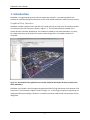
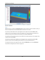
Figure 1-1: An example of the graphical user interface. Model of the Theater de Vest created by Van
Hooft Adviesburo. ......................................................................................................................................... 1
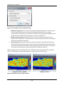
Figure 1-2: An example of the 3D Results view, showing occupants gathering at a refuge area before
proceeding to elevators. Transparency has been used to help view the occupants.................................... 2
Figure 1-3: An example time history graph .................................................................................................. 2
Figure 1-4: The triangulated navigation mesh used to represent one floor in the model. .......................... 3
Figure 1-5: Models used for system requirements comparison ................................................................... 5
Figure 2-1: 3D and 2D views ......................................................................................................................... 8
Figure 2-2: Render options ......................................................................................................................... 10
Figure 2-3: Predefined groups .................................................................................................................... 12
Figure 3-1: Floor Creation panel ................................................................................................................. 13
Figure 3-2: Auto floor creation and sorting ................................................................................................ 14
Figure 3-3: Adding a new floor.................................................................................................................... 15
Figure 3-4: Floor property panel ................................................................................................................. 16
Figure 3-5: Drawing a room with the polygon tool..................................................................................... 17
Figure 3-6: Drawing a room with the rectangle tool .................................................................................. 17
Figure 3-7: Drawing plane property ............................................................................................................ 18
Figure 3-8: Adding a thin wall to a room .................................................................................................... 18
Figure 3-9: Dividing a room ......................................................................................................................... 19
Figure 3-10: Special case for drawing a thin wall........................................................................................ 19
Figure 3-11: Merging rooms ....................................................................................................................... 20
Figure 3-12: Separating a room .................................................................................................................. 20
Figure 3-13: Room properties panel ........................................................................................................... 20
Figure 3-14: Edit Speed Modifier dialog ..................................................................................................... 21
Figure 3-15: Make Doors Oneway dialog .................................................................................................... 22
Figure 3-16: Creating an obstruction .......................................................................................................... 23
Figure 3-17: Subtracting walls..................................................................................................................... 23
Figure 3-18: Door tool property panel ........................................................................................................ 24
Figure 3-19: Adding a thin door to connect two touching rooms .............................................................. 25
Figure 3-20: Adding a thick door in the empty space between two rooms ............................................... 26
Figure 3-21: Door property panel ............................................................................................................... 26
Figure 3-22: Scripted Events dialog............................................................................................................. 27
Figure 3-23: Stair geometry requirements ................................................................................................. 27
Figure 3-24: Property panel for the two-point stair tool ............................................................................ 28
Figure 3-25: Drawing stairs with the two-point stair tool .......................................................................... 28
Figure 3-26: Property panel for the one-point stair tool ............................................................................ 29
Figure 3-27: Drawing stairs using the one-point stair tool ......................................................................... 29
Figure 3-28: Stair property panel ................................................................................................................ 30
Figure 3-29: Stair door property dialog ...................................................................................................... 30
viii