1
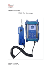
FIM-1
Fiber Inspector
(Fiber Optic Video Microscope)
User
Manual
CATALOGUE
SAFE GUARD............................................................................................................................3
1. FIM-1 Fiber Video Microscop............................................................................................. 4
1.1 Magnification.............................................................................................................. 4
1.2 Kinds of magnification as follows.............................................................................. 5
1.3 Enlarged Area..............................................................................................................5
2. Probe Introduction..............................................................................................................5
2.1 Constitution................................................................................................................. 6
2.2 Microscope Lens......................................................................................................... 6
2.3 Barrel Assembly.......................................................................................................... 6
2.4 Tip............................................................................................................................... 6
2.5 The installation and use of E2000-APC-F test tip:..................................................... 7
2.6 Tips introduction......................................................................................................... 8
2.7 Attention Points...........................................................................................................8
3. Monitor Introduction............................................................................................................9
3.1 Installation before using..............................................................................................9
3.2 DM35 display..............................................................................................................9
3.3 Power status showing through 4 LED.......................................................................11
3.4 The back part............................................................................................................. 11
3.5 The flank part............................................................................................................ 12
3.6 Introduction for charging.......................................................................................... 12
3.7 USB application........................................................................................................ 12
3.8 FIM-1 Allocation....................................................................................................12
4. Software Installation.......................................................................................................... 12
4.1 Hardware and Driver Installation:..........................................................................13
4.2 Software Installation and Application.......................................................................14
2
SAFE GUARD
Thank you for purchasing our product FIM-1 Fiber Video Microscope.
Before assembly and use, make sure that all of parts are carefully read when
utilizing the microscope, please pay attention to the following conventions.
WARNING: Refers to a potential personal hazard. It requires a procedure which,
if not correctly followed, may result in bodily harm or injury. To avoid the
electricity attack, do not disassemble the product privately. Only the stuffs are
allowed to maintain the trouble.
CAUTION: Refers to a potential product hazard. It requires a procedure which,
if not correctly followed, may result in component damage. Only the stuffs are
allowed to maintain the trouble.
IMPROTANT: Refers to any information regarding the operation of the
product which you should not overlook.
3
1. FIM-1 Fiber Video Microscop
FIM-1 Fiber Video Microscope can offer 650 magnification for the
fibers of 125um(diameter), single-mode and multi-mode are all
included. ( based on the magnification of the 9 inch display,which
can inspect 685000um end-face.) The enlarged picture is then sent
to the display through a video signal. Consequently the status of
fiber end-face is showed clearly.
FIM-1 features its unique configuration, because of which many
places can be inspected conveniently. For example, it can test the
patch cord directly. It can work with either male connector ends or inspect through female
bulkhead adapters. As a result, many hard-to-reach connectors that are installed on the
‘backside’ of patch panels or inside hardware devices can be easily inspected. It eliminates the
need to access the backside of patch panels or disassemble hardware devices, bringing more
convenience to the inspection.
Meanwhile, it avoids the potential eyes hazard, which may be caused by laser signal sent out
from fibers if you inspect them directly. Since the product test the fiber through a display,
such problem is totally not existed.
Actually, FIM-1 can be applied to anther situations familiar with the testing circumstance. It is
suitable for the archaeological study. Besides, some special electronic kits and deep-hole
plug-in can also be detected and so on. This book only refers to the application of optical
fiber.
Magnification of FIM-1-P
1.1
Magnification
FIM-1 enlarges the picture through an optical system and output them by CCD camera.
Owing to its complex configuration and small size, the amplification is stably decided by the
multiple of objective lens and the dimension of CCD. The larger the display is, the more
magnification it offers. Normally the size is 3.5inch or 5.6inch or 9inch or 14inch. The size of
PC display is 15inch or 17inch. When observing the image, to obtain a clear picture, you can
adjust the contrast and brightness based on the spot light.
1.2
Kinds of magnification as follows
Display 3.5inch 5.6inch 9inch 15inch 17inch
4
Index
Diameter
2.5
Magnification 200
4.5
360
8.1
650
12.3
980
14.5
1280
Note: 1) The data of diameters above are measured directly.
2) The magnification is calculated based on the fiber of 125um
1.3
Enlarged Area
As for the fiber ferrule, the detected size can reach up to 0.35mm diameter, which contains,
not only the end-face of 125um fiber in the middle, but also the ceramic surface around.
Adjusting the handle slightly will also help you obtain more enlarged ceramic area.
2.
Probe Introduction
Body Part
2.1 Constitution
A Handle: the handle houses many things, like CCD camera, optical structure, optical
routine system, coaxial lamp-house, focus control structure and video output, power supply
5
system and so on. The output is PAL.
B The Inner Structure of Handle is so compact and complex that, if long time work it will
cause a fever. This isn’t the mechanical failure but normal phenomena. If disassemble handle
personally, it may cause damage. Meanwhile, you will lose the chance to troubleshoot freely.
2.2 Microscope Lens
A On the front of the handle locates FIM-1-P optical system and the front end comes a
lens-bar.
B The Barrel Assembly, mounted on the front body, houses lens-bar inside and used to
match different tips. Turing the focusing wheel will change lens-bar meanwhile.
2.3 Barrel Assembly
Barrel Assembly plays a vital role in joining or fixing various tips.
2.4 Tip
To inspect different fibers, kinds of tips are needed. When using the tip, make sure the
connection between barrel assembly and tip is firm enough.
Pictures of tips are as follows:
Standard Tips: Female tips --FC/SCST-F、LC/MU-F
Male tip --2.5PC-M tip
Other tips are for optional selection (like FC-APC-F、SC-APC-F and 2.5APC-M as below)
2.5 The installation and use of E2000-APC-F test tip:
1. The flat side of the object lens must installed according to the E2000-APC-F test tip as
showed in the first picture.
6
2. With the installed test tips, when you plug the probe into the adapters,please plug in with
right the direction and plug to the end to obtain the best inspection result.(As showed in
the pictures below)
Note: Because of the limited space, tips are not listed fully. Please contact us for further
information.
7
2.6 Tips introduction
Tips
FC/SC/ST-F
LC/MU-F
2.5PC-M
FC-APC-F
SC-APC-F
Introduction
insert to the FC/SC/ST flange to inspect female fiber ends.
insert to the LC/MU flange to inspect female fiber ends, no
need to remove the fibers around when the connector port
is of high-density (dual use)
Insert directly to inspect male fiber ferrules (normally
SC,PC,ST three types)
Insert to the FC flange to inspect APC female fiber ends
insert to the SC flange to inspect APC female fiber ends
2.7 Attention Points
As pictures shown above, please pay attention to the following when using different tips:
1) When using the tip, do not rotate it once insert. Screwing the retaining nut on the barrel
assembly works.
2) When removing the tip or barrel assembly, make sure the removing direction is along the
beeline rather than laterally.
8
3. Monitor Introduction
FIM-1 (3.5 inch display)
The display eliminates the need to further conversion,
magnification can reach up to 600 times. You can
observe directly the fiber of 26000um ends on 3.5
inch display. High pixel and brightness enable the
display to inspect even 0.75um defaults. Working
time can last 5 hours above with lithium battery
supply. Power run-out alarm 、 hand-held design,
bring you more convenience.
3.1
Installation before using
The utilization of FIM-1-P is simple. Plug the connector of probe into the DM35
display as picture shown and press the button to start working.
3.2
DM35 display
DM35 means the 3.5 inch display, resolution can reach up to 224640 matrix (960*234).
high brightness, video input is PAL/NTSC (dual modulation).
Function keys on the operation panel
9
1) Power Run-Out Alarm: charge the battery immediately when the red light on (To avoid
extreme discharging which may destroy the lifetime.)
2) Power Indicator: indicate power on when the green light on
3) ON-OFF Switch: press to start working
4) Brightness Control: adjust the brightness by rotating right or left
5) Charger Port: connect the charger located at the end of the display
6) Body Interface: connect the probe to inspect fiber ends.
7) Contrast Control: adjust the contrast by rotating right or left
8) Battery Checking Switch: to show the battery capacity.
9) Power Status Display: to show the battery power status through four indicating lights
(Please check the power state before working)
10) 3.5 Inch Display
10
3.3
Power status showing through 4 LED
LED
4 lighting light
3 lighting light
2 lighting light
1 lighting light
3.4
Battery Power Balance
100%-75%
75%-50%
50%-30%
30%
Time Balance
6-5 hours
5-4 hours
4 hours
2 hours
The back part
The hook can be hanged on the pillar or be folded down into the recessed area for storage,
also the magnet can be absorbed to devices, all these can bring you convenience during the
inspection.
11
3.5
The flank part
USB2.0 port mounted. For more details, please refer to FIM-1 data image operation.
3.6
Introduction for charging
Battery: DM35 display can work 5 hours above with lithium battery supply, working
voltage 12V and the power capacity 2200mAh.
Activating: Before the utilization, activate the battery. Discharge the battery completely
first(when the red light dies), then make certain that recharge the battery more
than 10 hours,
repeat this procedure 2-3 times, the battery will be fully
activated.
Charging:
3.7
Battery of charging is safety and fast. 3 hours shortest charging time. When the
power indicator turns green, continue to charge one more hour, which will be the
perfect time. Monitor can work meanwhile.
USB application
DM35 display can output the image through USB wire to the computer. USB accessory is
provided optional.
3.8
FIM-1 Allocation
NO.
Name
Quantity
1
FIM-1-P probe
1 pcs
2
3.5 Inch Display
1 pcs
3
LC/MU-F ,SC/FC/ST-F
2 pcs
4
2.5mm PC Male Tip
1pcs
5
Lithium Battery and Charger
1 pcs
6
Bag
1 pcs
12
4. Software Installation
4.1 Hardware and Driver Installation:
1. When you firstly plug the USB probe into the computer USB port, you will be informed to
install the USB driver. As showed in the image below:
2. Select the second selection and click next to start installation. Find where you have placed
the USB Driver in your computer and click next.
3. Keep clicking next and you will be next informed with the message below and select the
left selection.
13
4.You will be informed next that the windows files will be changed into unrecognized ones.
Please click “Cancel” to ignore this message and you will finish the installation soon.
4.2 Software Installation and Application
1. Double click the icon above to start the software.
14
2. File---Open Device
3. Select “szetUSB Device” in the first check box and click OK to continue.
15
4. You will then see the end-face in the software but sometimes the image would be elliptical,
not the round. Then you have to change the Properties of the device as showed in the
image below::
5. Changed the value of the first check box into “PAL_D”. Then double click the screen
twice and the image will be round.
16
6. Save the image of the inspection result:
17
7. Save the video of the inspection result. “View---Capture”, and then press “record” to start:
18
8. Modify the “brightness” and the “contrast”:
The first selection is “brightness” and the second one is “contrast”. The third and fourth one
have no effect to image quality because the image is black and white. The last one is
“definition”. The best definition will be “3 or 4”.There will be too much noise if the definition
is too high(Up to 6).
19