1
Leica F12 I
User Manual
Table of Contents
General Instructions
Safety Concept
Symbols Used
Safety Instructions
3
4
5
6
Leica
F12
I
Floor Stand
Introduction9
Overview (Sample Configuration)
10
Installation
Pedestal and Large Vertical Column
Large Horizontal Arm and Flex-arm
Small Vertical Column: Assembly
Small Vertical Column: Montage
Small Vertical Column: Height Adjustment
Focusing Arm: Configuration 1 for Table Inspections
Focusing Arm: Configuration 2 for Table Inspections
Focusing Arm: Configuration 3 for Table Inspections
Focusing Arm: Configuration 1 for Wall Inspections
Alternative: Variable Focusing Arm
Leica F12 I Floor Stand
12
13
14
15
16
17
18
19
20
21
Microscop Installation
Optics Carrier and Objective
Tube and Eyepieces
Dioptric Correction and Parfocality
23
24
25
Operation
Adjusting the Joint Resistance
Balancing the Flex-arm
Adjusting the Working Height of the Microscope
Safe Transport
27
28
29
30
Illumination
(Optional) Leica LED1000 Combi Controller
Leica High-power Spotlight
Leica 2-arm LED Spotlight
33
35
36
Appenidx
Care and Maintenance
38
Troubleshooting39
Technical Data
40
Dimensions41
Manual
2
General Instructions
Safety Concept
Before installing the Leica F12 I floor stand or
using it for the first time, please read the "Safety
Concept" brochure provided. It contains additional information on handling and care.
Use in clean rooms
Leica F12 I Floor Stand
The Leica F12 I series can be used in clean rooms
without any problems.
Cleaning
ϘϘ Do not use any unsuitable cleaning agents,
chemicals or techniques for cleaning.
ϘϘ
Never use chemicals to clean colored
surfaces or accessories with rubberized
parts. This could damage the surfaces, and
specimens could be contaminated by abraded particles.
ϘϘ
In most cases, we can provide special solutions on request. Some products can be
modified, and we can offer other accessories for use in clean rooms.
Manual
Servicing
ϘϘ Repairs may only be carried out by Leica
Microsystems-trained service technicians.
Only original Leica Microsystems spare
parts may be used.
Responsibilities of person in charge of
instrument
ϘϘ Ensure that the Leica floor stand is operated, maintained and repaired by authorized
and trained personnel only.
3
Safety Concept
The Leica F12 I is shipped with an interactive
CD-ROM, where you can find all relevant user
manuals. Keep it in a safe place, and readily
accessible to the user. User manuals and
updates are also available for you to download
and print from our web site www.leica-microsystems.com.
The "Safety Concept" brochure contains additional safety information regarding service
work, requirements and the handling of the
floor stand, the installed stereomicroscope, the
electrical accessories as well as general safety
instructions.
Leica F12 I Floor Stand
You can combine individual system articles
with articles from external suppliers (e.g. cold
light sources, etc.). Please read the user manual
and the safety requirements of the supplier.
Before installing, operating or using the instruments, read the user manuals listed above.
In particular, please observe all safety instructions.
To maintain the unit in its original condition
and to ensure safe operation, the user must
follow the instructions and warnings contained
in these user manuals.
Manual
4
Symbols Used
Warning of a danger
This symbol indicates especially important information that must be read and
complied with. Failure to comply can cause the
following:
ϘϘ
Hazards to persons!
ϘϘ
Instrument malfunctions and damage.
Danger due to hot surface
This symbol warns against touching hot
surfaces, such as light bulbs.
Important information
This symbol indicates additional information or explanations that are intended
to provide clarity.
Warning of hazardous electrical voltage
This symbol indicates especially
important information.Failure to
observe can cause the following:
ϘϘ
Hazards to persons!
ϘϘ
Instrument malfunctions and damage.
Leica F12 I Floor Stand
Manual
5
Safety Instructions
Intended use
ϘϘ Refer to the "Safety Concept" brochure.
Non-intended use
ϘϘ Refer to the "Safety Concept" brochure.
The instruments and accessories described
in this manual have been safety-tested and
checked for possible hazards. The responsible
Leica affiliate must be consulted whenever
the instrument is altered, modified or used in
conjunction with non-Leica components that
are outside of the scope of this manual.
Leica F12 I Floor Stand
Unauthorized alterations to the instrument or
noncompliant use shall void all rights to any
warranty claims.
Requirements to be met by the operator:
ϘϘ Refer to the "Safety Concept" brochure.
Ensure that:
Installation location
ϘϘ Refer to the "Safety Concept" brochure.
ϘϘ
Electrical components must be placed at
least 10 cm away from the wall and from
flammable substances.
ϘϘ
Avoid large temperature fluctuations, direct
sunlight and vibrations. These conditions
can distort measurements and micrographic images.
ϘϘ
In warm and warm-damp climatic zones,
the individual components require special
care in order to prevent the build-up of
fungus.
Manual
ϘϘ
The Leica F12 I is operated, maintained and
repaired only by authorized and trained
personnel.
ϘϘ
All operators have read, understood and
observe this User Manual, and particularly
the safety regulations.
6
Safety Instructions (continued)
Repairs, service work
ϘϘ Refer to the "Safety Concept" brochure.
ϘϘ
Only original Leica Microsystems spare
parts may be used.
ϘϘ
Before opening the instruments, switch off
the power and unplug the power cable.
ϘϘ
Touching the live electric circuit can cause
injury.
Transport
ϘϘ Always use the original packaging for shipping or transporting the Leica F12 I.
ϘϘ
In order to prevent damage from vibrations,
disassemble all moving parts that (according to the user manual) can be assembled
and disassembled by the customer and
pack them separately.
Leica F12 I Floor Stand
Because the pedestal of the Leica
F12 I is particularly heavy, always
request assistance from another person when
transporting it!
Installation in third-party products
ϘϘ Refer to the "Safety Concept" brochure.
Disposal
ϘϘ Refer to the "Safety Concept" brochure.
Legal requirements
ϘϘ Refer to the "Safety Concept" brochure.
EC Declaration of Conformity
ϘϘ Refer to the "Safety Concept" brochure.
Manual
7
Leica F12 I
Floor Stand
Leica F12 I Floor Stand
Manual
8
Introduction
Congratulations on purchasing the Leica F12
I by Leica Microsystems. The particular design
of this floor stand makes it ideally suited for
mobile examinations of specimens. Whether
material inspection, quality control or art
restoration—in fact anywhere you might need
a mobile microscopy workstation, you will find
that the Leica F12 I is a flexible, sturdy and costeffective solution.
As versatile as your work
The Leica F12 I supports the Leica stereomicroscopes M50, M80 and the entire Leica S series.
Not only are there many models to choose from,
but there is also a range of accessories to fulfill
every possible wish. Even if your requirements
are like no one else's: Your Leica consultant will
configure a workstation that meets your needs
perfectly.
Leica F12 I Floor Stand
For more information about Leica Microsystems products and services and the
address of your nearest Leica representative, please visit our website:
www.leica-microsystems.com
Thank you for choosing our products. We hope
that you will enjoy the quality and performance
of your new floor stand.
Leica Microsystems (Schweiz) AG
Industry Division
CH-9435 Heerbrugg
Manual
9
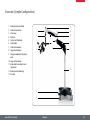
Overview (Sample Configuration)
1 Rotary knob for joint brake
2 Small vertical column
3Microscope
4Pedestal
5 Castors with footbrakes
6 Cable holder
7 Small horizontal arm
8 Large horizontal arm
9 Storage compartment for power
pack
10 Large vertical column
11 Brake knob for locking the vertical position
12 Rotary knob for balancing
13Flex-arm
11
1
2
12
13
6
1
7
9
3
8
1
10
4
5
Leica F12 I Floor Stand
Manual
10
Installation
Leica F12 I Floor Stand
Manual
11
Pedestal and Large Vertical Column
An M5 Allen key is required for
assembly (not provided).
2. Insert the large vertical column into the
pedestal.
3. Use the Allen key to tighten both Allen
screws.
The pedestal and the large vertical
column are very heavy. Always request
assistance for assembly!
Assembly
1. Move the pedestal to a flat, level surface
and lock all 4 footbrakes.
4. Cover the screw holes using the cover caps.
Leica F12 I Floor Stand
Manual
12
Large Horizontal Arm and Flex-arm
The large horizontal arm and the flexarm are very heavy. Always request
assistance for assembly!
Leica F12 I Floor Stand
Assembly
1. Place the large horizontal arm onto the
large vertical column.
Manual
The large horizontal arm does not need
to be fastened, because the weight of the
structure ensures a secure connection.
13
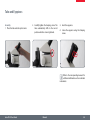
Small Vertical Column: Assembly
The small vertical column connects the
Leica floor stand to the actual microscope assembly.
Assembly
1. Press the small vertical column onto the
coupling piece from below.
2. Attach the small vertical column using the
4 Allen screws provided.
Leica F12 I Floor Stand
Manual
14
Small Horizontal Arm: Assembly
Assembly
1. Remove the wingscrew from the small horizontal arm.
2. Push the small horizontal arm through the
hole in the small vertical column. Here, the
beveled side must point in the direction of
the outer knob.
3. Tighten the wingscrew.
4. Tighten both locking screws as much as
necessary for your work.
Leica F12 I Floor Stand
Manual
15
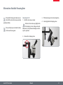
Small Horizontal Arm: Height Adjustment
Without exception, the two safety
screws must never be removed!
Height adjustment
1. Hold the small horizontal arm securely.
2. Unscrew the safety ring.
The small horizontal arm can be set to
any height. As necessary, it can be moved
freely at the lower end of the column with the
safety ring loosened.
3. Move the small horizontal arm to the desired position.
4. Tighten the safety ring.
Leica F12 I Floor Stand
Manual
16
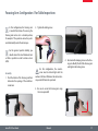
Focusing Arm: Configuration 1 for Table Inspections
In this configuration, the focusing arm
is inserted from below. If necessary, the
focusing arm can be set in a slanted position,
for example if the specimen cannot be positioned horizontally under the microscope.
2. Tighten the locking screw.
For the greatest possible stability, you
should extend the small horizontal arm
as little as possible in order to reduce a lever
effect.
Assembly
1. Push the holder of the focusing arm from
below into the opening of the small horizontal arm.
For this configuration, the counterscrew must be locked tight with the
washer at all times. Otherwise the entire microscope could fall onto the specimen!
4. Unscrew both clamping screws on the focusing arm. Modify the tilt of the focusing arm
and tighten the locking screw.
3. Be sure to secure the focusing arm using
the screw provided!
Leica F12 I Floor Stand
Manual
17
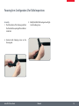
Focusing Arm: Configuration 2 for Table Inspections
Assembly
1. Push the holder of the focusing arm from
the front into the opening of the small horizontal arm.
3 Modify the tilt of the focusing arm and tighten the locking screw.
2. Unscrew both clamping screws on the
focusing arm.
Leica F12 I Floor Stand
Manual
18
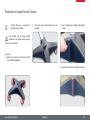
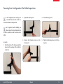
Focusing Arm: Configuration 3 for Table Inspections
In this configuration, the focusing arm
is inserted from above. This results in a
vertical view down on the specimen.
2. Tighten the locking screw.
4. Tilt the focusing arm 90°.
3. Unscrew both clamping screws on the
focusing arm.
5. Tighten the clamping screws on the focusing arm.
For the greatest possible stability, you
should extend the small horizontal arm
as little as possible in order to reduce a lever
effect.
Assembly
1. Push the holder of the focusing arm from
above into the opening of the small horizontal arm.
Leica F12 I Floor Stand
Manual
19
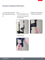
Focusing Arm: Configuration for Wall Inspections
tion.
Specimens on a wall or easel can best be
examined using this assembly configura-
Assembly
1. Extend the small horizontal arm far out and
push the holder of the focusing arm from
above into the opening.
3. Additionally secure the focusing arm using
the counter-screw and washer provided.
2. Tighten the locking screw.
Leica F12 I Floor Stand
Manual
20
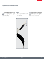
Alternative: Variable Focusing Arm
Adjusting the tilt
1. Hold the microscope securely.
Hold on to the microscope tightly while
the clamping screw is being unscrewed.
Otherwise it can tip forward abruptly and destroy the specimen!
The variable focusing arm makes it possible to tilt the entire microscope assembly
quickly and safely.
The assembly steps are identical to those
for the basic focusing arm.
3. Tilt the microscope to the desired position.
4. Securely tighten the clamping screw.
2. Unscrew the clamping screw.
Leica F12 I Floor Stand
Manual
21
Microscope Installation
Leica F12 I Floor Stand
Manual
22
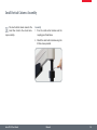
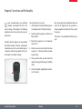
Optics Carrier and Objective
Assembly
1. Insert the optics carrier into the focusing
arm.
2. Securely tighten the clamping screw.
Leica F12 I Floor Stand
3 Screw the objective into the optics carrier.
Regularly check whether the clamping
screw is still tight.
Manual
23
Tube and Eyepieces
Assembly
1. Place the tube onto the optics carrier.
2. Carefully tighten the clamping screw. The
tube automatically shifts to the correct
position when the screw is tightened.
3. Insert the eyepieces.
4. Secure the eyepieces using the clamping
screws.
Refer to the corresponding manuals for
additional information on the individual
instruments.
Leica F12 I Floor Stand
Manual
24
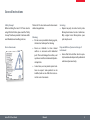
Dioptric Correction and Parfocality
Leica stereomicroscopes are parfocally
matched. A prerequisite for this is the
correct setting of the diopters. The following
adjustments have to be carried out only once
by each user.
Therefore, all Leica eyepieces are also available
with built-in dioptric correction, allowing the
stereomicroscope to be used without glasses
even by those with vision problems. The correction comprises ±5 diopter settings.
Using the Dioptric Correction
1. Set the dioptric correction of both eyepieces
to the mid position ("0" diopter settings).
2. Look through the eyepieces and focus on a
flat specimen.
3. Rotate both eyepieces to the maximum
value of "+5".
Now, if you adjust the magnification from the
lowest to the highest level, the specimen is
always brought into sharp focus. If not, repeat
the process.
The system is now parfocally matched to your
eyes.
4. Hold one eye closed and rotate the other
eyepiece in "-" direction until the specimen
appears sharp.
5. Then, open the other eye and correct the
diopter settings until the image is uniformly
sharp.
6. Select the highest magnification and refocus if necessary.
Leica F12 I Floor Stand
Manual
25
Operation
Leica F12 I Floor Stand
Manual
26
Adjusting the Joint Resistance
Adjusting the joint resistance makes
it possible to customize how easy or
difficult it is to move the arm.
Adjusting the Joint Resistance
ϘϘ Loosen the articulation brakes to make the
corresponding element move more easily.
ϘϘ
Leica F12 I Floor Stand
Tighten the articulation brakes to make
it harder to move the corresponding
element.
Manual
27
Balancing the Flex-arm
For safety reasons, the flex-arm must be
balanced after every adjustment to the
configuration.
During the balancing process, be aware
that the microscope side tends to be
slightly lighter.
Balancing the Flex-arm
1. Hold the microscope securely.
2. Loosen the brake knob for the vertical position lock. The flex-arm is now released.
3. By manually moving the flex-arm, check
whether the microscope side is too light or
too heavy.
•
If the microscope is too heavy, turn the
knob counterclockwise.
•
If the microscope is too light, turn the knob
clockwise.
Never balance the flex-arm over a specimen.
The Leica F12 I is designed for weights
between 1.5 kg and 6.5 kg.
The correct direction of rotation (lighter/
heavier) is indicated below the rotary
knob.
Leica F12 I Floor Stand
Manual
28
Adjusting the Working Height of the Microscope
Never adjust the working height over a
specimen!
Adjusting the working height
1. Carefully release the brake knob on the
front end of the flex-arm.
2. Move the microscope to the desired
working height.
3. Tighten the brake knob.
Leica F12 I Floor Stand
Manual
29
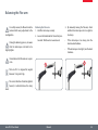
Safe Transport
If the floor stand begins to swing out
of control, risk of injury results. For this
reason, the Leica F12 I may only be moved with
the flex-arm folded together and locked!
Feet in lightweight shoes could become
trapped beneath the casing of the base
during transport!
Moving the floor stand
1. Position the flex-arm approximately horizontal.
4. Release the articulation brakes and fold the
flex-arm together.
2. Tighten the brake knob for the vertical
position lock. The flex-arm is now locked.
Due to the rotation stop device, the flexarm can be moved only in one direction
above the large horizontal arm.
3. Remove the power cable.
Leica F12 I Floor Stand
Manual
30
Safe Transport (continued)
5. With your foot, push up the footbrake
release levers to release the footbrakes.
6. Hold the floor stand securely by the column
and push it to the desired location.
7. Lock all four footbrakes.
8. Connect the power cable.
For safety reasons, always push the floor
stand—never pull it.
Leica F12 I Floor Stand
Manual
31
Illumination
Leica F12 I Floor Stand
Manual
32
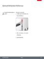
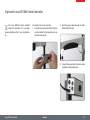
(Optional) Leica LED1000 Combi Controller
The Leica LED1000 combi controller
allows the operation of 2 Leica highpower spotlights and/or 1 Leica ring illuminator.
Assembling the combi controller
1. Using the screw provided, fasten the Leica
combi controller to the connector piece on
the small vertical arm.
2. Feed the power cable through the cable
holder on the flex-arm.
3. Connect the power cable to the Leica combi
controller and the power pack.
Leica F12 I Floor Stand
Manual
33
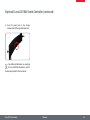
(Optional) Leica LED1000 Combi Controller (continued)
4. Store the power pack in the storage
compartment of the large horizontal arm.
For additional information on operating
the Leica LED1000 illumination, refer to
the manual provided for this instrument.
Leica F12 I Floor Stand
Manual
34
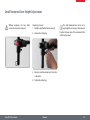
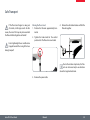
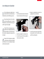
Leica High-power Spotlight
The Leica high-power spotlight can be
attached either to the articulated arm (as
illustrated here) or to the flexible gooseneck.
Assembly
1. Screw the articulated arm into the threaded
hole on the underside of the focusing arm.
4. Release the articulated arm and aim the
spotlight in the desired direction.
The two threaded holes in the articulated arm have differing sizes. The smaller
threaded hole is connected to the focusing arm
and the larger to the spotlight.
The LED of the Leica high-power spotlight becomes only slightly warm during
operation. Nevertheless, be sure that the specimen cannot be damaged by coming too close
to the light.
Always hold the high-power spotlight
securely when releasing the articulated
arm. Otherwise it can tip downward abruptly
and destroy the specimen!
Leica F12 I Floor Stand
2. Attach the spotlight to the articulated arm.
3. Connect the power pack for the spotlight to
the Leica combi controller.
Manual
5. Secure the power cable using the Velcro
strips provided so that the cables cannot
get in the way during work.
35
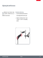
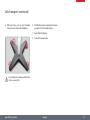
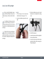
Leica 2-arm LED Spotlight
The Leica 2-arm LED spotlight is equipped with two LED lamps. It only uses one
terminal, however, on the Leica combi controller.
For installation, the focusing arm must
be removed. In doing so, request assistance from another person and be sure that
the specimen is not located directly below the
microscope.
Assembly
1. If the focusing arm has already been
installed, remove it (see pages 17–19).
2. Screw the installation ring onto the spotlight.
The LEDs of the Leica 2-arm LED spotlight become only slightly warm during
operation. Nevertheless, be sure that the specimen cannot be damaged by coming too close
to the light.
Leica F12 I Floor Stand
3. Slide the installation ring over the small
horizontal arm and tighten the locking
screw.
4. Install the focusing arm.
5. Connect the power pack for the spotlight to
the Leica combi controller.
5. Secure the cables using the Velcro strips
provided so that the cables cannot get in
the way during work.
Manual
36
Appendix
Leica F12 I Floor Stand
Manual
37
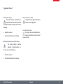
Care and Maintenance
General
ϘϘ For good optical results, it is important to
keep optical components clean.
ϘϘ
Always cover the stereomicroscope with
the dust cover included in the delivery
when the instrument is not in use.
ϘϘ
If an optical surface is very dirty or dusty,
flush it using a syringe or clean it using a
camelhair brush before attempting to wipe
it off.
ϘϘ
Optical surfaces should be cleaned using
a lint-free cloth, lens cloth or cotton swab
soaked in methanol or a commercially
available glass cleaner. Do not use alcohol.
Leica F12 I Floor Stand
ϘϘ
Avoid excessive use of solvents. The lintfree cloth, lens cloth or cotton swab should
be soaked with solvent, but not so wet that
solvent runs over the lens.
Manual
38
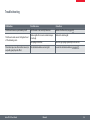
Troubleshooting
Malfunction
Possible cause
Correction
The flex-arm moves up or down by itself.
The flex-arm is not correctly balanced.
Balance the flex-arm (see page 28).
Total weight of accessories and microscope
is too high.
Reduce the total weight.
Gas spring is defective.
Have the gas spring replaced by Leica service.
The articulation brakes are too tight.
Loosen the articulation brakes (see page 27).
The flex-arm sinks even at the highest level
of the balancing scale.
The microscope can either not be moved, or
only with great physical effort.
Leica F12 I Floor Stand
Manual
39
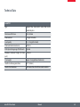
Technical Data
Leica F12 I
Type
Compact floor stand with 4 castors that can be
locked into place
Dimensions of the base
608 × 608 mm
Maximum load
6.5 kg (at the holder)
Load capacity
1.5 – 6.5 kg (at the holder)
Maximum horizontal extension
1224 mm
Vertical positioning range of the flex-arm
500 mm
Minimum instrument height (for trans- 1680 mm
port)
Stand weight
Approx. 100 kg (without attachments)
Interface to focusing arms/drives:
5/8" (15.8 mm)
Interface for illuminators
M6 threaded hole for LED1000 combi controller
Leica F12 I Floor Stand
Manual
40
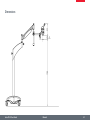
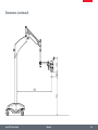
Dimensions
Leica F12 I Floor Stand
Manual
41
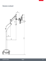
Dimensions (continued)
Leica F12 I Floor Stand
Manual
42
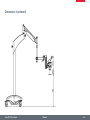
Dimensions (continued)
Leica F12 I Floor Stand
Manual
43
Dimensions (continued)
Leica F12 I Floor Stand
Manual
44