1
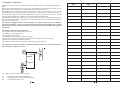
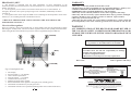
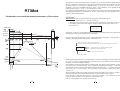
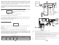
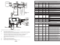
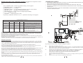
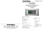
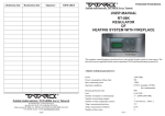
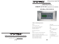
RT08os/2015/v3.5 ANG TITANIUM
Zakład elektroniczny TATAREK Jerzy Tatarek
USER MANUAL
v.3.5 (02.02.2015 program version from 3.5)
FIREPLACE OS/COMBUSTION OPTIMIZER
RT-08os TITANIUM
1.Basic technical parameters
Zakład elektroniczny TATAREK Jerzy Tatarek
50-559 Wroclaw, 75 Swieradowska st.
ph. (071) 367-21-67, 373-14-88, fax 373-14-58; Tax index number 899-020-21-48;
Bank account: BZ WBK S.A. WROCLAW 6910901522-0000-0000-5201-9335
www.tatarek.com.pl.; E-mail: [email protected]
16
Power
Auxiliary power source
Power consumption without load
Maximum connection power
230V/50Hz
Rechargeable battery 4,8V/60mA
5W
250W
Operation conditions
Housing protection class
Fuse
Number of outputs to control the flap drive
Number of nonvoltage control outputs
Number of outputs to control the choke valve drive
0-40 C, humidity 10-90%
(no condensation)
IP41
6,3A/250V
1 * 250W/230V/50Hz
1 * NO and NC contacts
1 * 5V/500mA/DC
Number of temperature sensors
1 * Thermocouple type K(0...+1300 oC )
Temp. measurement precision
5C
Temp. measurement resolution
1C
o
o
o
1
2. Principle of operation
With the air choke valve the regulator controls the combustion process and maintains the embers
phase.
By lowering the combustion curve in the phase of increasing temperature and by raising it in the
phase of decreasing temperature the regulator extends the combustion process.
The ragulator starts operating as the furnace door closes (opening sensor of the door), supervises the
combustion process (temperature sensor of combustion, air choke valve), shuts off air supply as
there's the embers phase in the furnace. Additionally the regulator can increase the chimney draught
in the heating phase( flap drive of the by-pass of the heat accumulation module).
In emergency situations (power decrease as well) the choke valve opens, enabling a full burn-out of
the fuel. The special input for connecting any external control device of CO concentration increases
the safety of a fireplace user.
The regulator is equipped with its own emergency power supply. The pause in power supply up
to 8secs doesn't affect regulator operation because during that time the buffer power supply
switches on. If the pause is longer the choke valve opens up in emergency and then the regulator
switches off.
Admission
date
Realization
date
Signature
Advantages of the combustion optimizer:
-lowering the maximum combustion temperature
-extending the combustion process
-decreasing fuel consumption
-extending the exploitation time of fireplace inputs
-shutting off air supply after ending the combustion (preventing the furnace cool-off)
-optimal use of the heat accumulation module
-cooperation with CO sensors (opening up the fresh airing in emergency)
CHIMNEY
The regulator can control a fireplace without the opening sensor of the door. In that case the
buttons on the front panel are used.
FIREPLACE
Fig.1 Basic operation scheme of the regulator
T1
D1
PP
Temperature sensor of the combustion
Opening sensor of the furnace door (option)
Controlled air choke valve
2
15
Remarks
2.1 Operation phases of the regulator
CE CONFORMITY DECLARATION
Ref. No. 58.RT.01.2007/1/B
We,
ZAKŁAD ELEKTRONICZNY TATAREK Jerzy Tatarek
75 Swieradowska St. , 50-559 Wroclaw
declare under our sole responsibility that
the product: Regulator of heating system with solar collector
model: RT-08, RT-08K, RT-08P, RT-08os
is in conformity with the basic requirements included in Directive EMC 2004/108/WE of 15.12.2004 (the
electromagnetic compatibility law of 13.04.07) and Directive LVD 2006/95/WE of 21.08.07 (Laws Journal
of 2007 No. 155 pos. 1098) regarding the requirements for electric devices.
To the conformity evaluation the following harmonized standards were used:
PN-EN 60730-2-1: 2002 PN-EN 60730-1: 2002 -
Automatic electric regulators for house usage and the like. Part 2-1:
Specific requirements regarding electric regulators for electric house
devices
Automatic electric regulators for house usage and the like.
Part 1: General requirements.
The regulator controls the combustion process as a cycle of the following phases:
1. F0/STOP - Standby phase. The regulator awaits opening the door and preparing the fuel
for the next heating. F0 is a temporary state to STOP. In the STOP state the choke valve
is closed.
2. F1 - Start phase. After loading the fuel and its lighting you close the furnace door. It's a
signal for the regulator that the combustion cycle has begun. The choke valve is fully
open.
3. F2 - Heating-up phase. After reaching the limit temperature the pass to the phase F3
follows.
4. F3, F4 - Phase of increasing temperature. The choke valve is gradually closed.
5. F5 - Burning phase. Awaiting the maximum temperature of the process
6. F6 - Phase of decreasing temperature. The choke valve is again gradually closed
7. F7 - Embers phase. Signalling the demand for replenishing the fuel
8. F8 - Phase of removing the exhaust gases. The choke valve first opens up and then
closes and there's the pass to the standby phase.
2.2 Air choke valve
The choke valve regulates air inflow to the combustion chamber dependent on the phase.
During the flap move of the choke valve the diode (9) lights. The blinking means a temporary
overload of the drive affected by met resistances.
2.3 Restricting the maximum temperature of the combustion
Exceeding the temperature defined by the parameter "T.max" causes closing the air choke valve
within the range of 10%...50% (Parameter "ChokeVTH" ) and the alarm turns on. The closing
o
process begins with 50 C before reaching this limit. Cancelling the alarm and the return to the
standard operation of the air choke valve occur if the temperature falls to T.max - 50oC.
Electromagnetic compatibility (EMC)- IT devices
PN-EN 55022: 2000 Characteristics of radioelectric noises. Acceptable levels and measurement methods
2.4 Programs-Variants of the operation of the regulator
Complementary information:
The basic function of the regulator is to optimize the combustion process by controlling the air choke
valve. The regulator can control a distribution of produced heat in the following variants (Fig.3
presents the right operation diagrams):
Laboratory IASE 51-618 Wroclaw, 1 Wystawowa st.
Program 1 “MAC”
Test report No.
39/DL/I/07 of 22.06.2007
41/DL/I/07 of 03.07.2007
Electronic Engineering Plant TATAREK
has initiated management system and complies with the following standard :
ISO9001: 2000 CERTIFICATE No. 133/2004 of 01.2004
Polish Foreign Trade Chamber
The last two digits of the year in which the CE marking was affixed: 07
Place of issue:
Manufacturer representative:
Wroclaw
Mirosław Zasępa
1. During the normal operation heated exhaust gases pass through the heat accumulation
module (MAC), where they give back heat, cooling off.
During the heating-up when the fireplace is cold , its draught can be insufficient. The regulator sets
the flap “K1”in the position of bypassing the MAC and directs the exhaust gases into the chimney.
After reaching the preset temperature (chimney is heated up) tha flap position is changed and the
exhaust gases are directed into the MAC
2. To the regulator you can connect an external control device of CO concentration. In
emergency the choke valve opens up improving a room ventilation, additionally the alarm switches
on.
3. The regulator turns on the outputALARM in case of damage of the temperature sensor of the
furnace (T1) or exceeding the limit concentration of CO2.
Program 2 “WATER”
Date of issue:
Position:
08.2007
Konstruktor
14
1. The fireplace is equipped with the water attachment. If water temperature in the
attachment reaches the preset value (sensor T2) and is higher than the buffer temperature (T3)
then the pump “P1” , which loads the buffer, switches on.
2. The controlled flap “K1” directs warm exhaust gases into the water attachment when
there's a demand for warm water.
3
PROGRAM 3 „MIX”
WARRANTY
1. The fireplace is equipped with the water attachment. If water temperature in the
attachment reaches the preset value (sensor T2) then the pump “P1” , which receives heat (it loads the
buffer), switches on.
2. To the regulator you can connect an external control device of CO concentration. In
emergency the choke valve opens up improving a room ventilation, additionally the alarm
switches on.
3. The regulator turns on the output ALARM in case of damage of the temperature sensor of the
furnace (T1) or exceeding the limit concentration of CO2.
! CHOICE OF THE PROGRAM AND ITS SETTINGS ARE AVAILABLE IN THE
PARAMETERS OF LEVEL 3
3 Service of the regulator
There are elements on the control panel (Fig. 2). In the standby state only the green diode (7) lights
indicating the standby mode. The turn-on of the regulator follows after opening the furnace door.
After closing the door the combustion cycle starts, which is signaled by the green diode (8).
(CHOOSE)
1.Warranty is valid [24] months from the date of sale.
2.Producer does not take responsibility for any mechanical damages made by user.
3.MAKING REPAIRS OR MODYFYING THE DEVICE BY USER IS
FORBIDDEN AND CAUSES WARRANTY CANCELATION
4.Warranty card is valid only with date of sale, seller's signature and stamp
5.Warranty and after-warranty repairs should be done only by producer, damaged
regulators should be sent to producer in order to make all repairs needed.
6.Warranty protection involves the EU
7.Warranty does not exclude, not restrict and not suspend buyer’s rights coming from
the incompatibility of the article with the agreement (Laws Journal No. 141 Pos. 1176)
WARNING !
ANY MODIFICATION OF THE REGULATOR MADE BY USER CAN BE
THE CAUSE OF SAFETY CONDITIONS DETERIORATION AND CAN
EXPOSE THE USER TO ELECTRIC SHOCK OR DAMAGE DEVICES
SUPPLIED.
Connection cable of regulator may be replaced only
by producer or his authorized service locations
(MAN)
WARNING!
1. Producer does not take the responsibility for damage
caused by atmospheric discharge
2. and overvoltage in the mains
3. Burnt fuses are not subject to warranty replacement
Date of sale
Seller's signature and stamp
(CONFIRM)
1.
2.
3.
4.
5.
6.
7.
8.
9.
ARGO-FILM
Recycling Plant No. 6
180 Krakowska st., 52-015 Wroclaw
Worn out electronic
and electric devices must be transfered to ph.: 071 794 43 01,
0 515 122 142
the utilization collection place, where will
be accepted for free
Register No.. GIOS: E 0002240WZ
Fig.2 Control panel view
Text display
Increase button ”+” (or START)
Choice button of parameter
Decrease button „-” (or STOP)
Confirm button (or AUTO)
Manual operation button “MAN”
Status LED-diode of the regulator: emergency(red), standby (green)
LED-diode of combustion cycle (the green one)
LED-diode of choke valve operation (blinking means the overload of the drive)
4
Zakład elektroniczny TATAREK Jerzy Tatarek
50-559 Wroclaw, 75 Swieradowska st
ph. (071) 367-21-67, 373-14-88, fax 373-14-58; tax index number 899-020-21-48;
Bank account : BZ WBK S.A. O/WROCŁAW 6910901522-0000-0000-5201-9335
www.tatarek.com.pl.; E-mail: [email protected]
13
The operation state is presented on the text display (1). The screens inform about the operation of
devices, temperature of the furnace; they make it possible to change the parameters etc..The change
of screen is done by pressing the CHOOSE button (3). If this is a screen that is able to change a
parameter, press the CONFIRM button(5), which causes blinking of the parameter field to be
changed. By pressing “+” (2) or “-” (4) one can alter its value.
By clicking the CONFIRM button (5) one confirms the changes - the parameter field stops blinking.
The changed parameter not confirmed for 10 secs is not accepted by the regulator and it recalls a
previous value of the parameter.
Combustion curve with the marked parameters of the control
3.1 Screens
Alarm screens is not seen till the following emergency situation takes place:
1. Damage of the sensor T1 . “T.Firep” shows up.
2. Damage of the internal sensor of the reference temperature. “Ref.Temp” shows up.
3. Exceeding of the limit concentration of CO by short-circuiting the contacts X1.
“Gas” shows up.
ALARM !!
T.Firep
choke valve
ChokeVF4
Emergency situation is accompanied both by a broken sound alarm that can be turned off by
pressing any button and a blinking of the red diode(7).
ChokeVF5
ChokeVF7
Screen of the regulator operation shows actual temperature of fireplace, level of choke valve
opening, phase of operation and possibly combustion error
(HA) By-pass flap is turned on (program “MAC”)
(WA) Activated flap that directs the heat into the water attachment(program „WATER”)
o
HA 1200
F1
50%
Ti.PDM
Combustion temp. (T1)/Possibly blinking „END”
(Demand fo r replenishing the fuel)
Level of choke valve opening
Phase of operation
Ti.STOP
DelayTim
T.Restar
Ti.F7
12
Time
Reaching the embers phase F7 is accompanied by a broken sound signal (switch-off with the button
(6) ), text “FuelOUT” and blinking of the green diode (8), which indicates the need for replenishing
the fuel in case of continuing the heating.
The regulator can run in the automatic or manual mode. The longer pressing “MAN” (6) about 2secs
causes the pass to the manual mode. That's signalled by blinking status diode (7). The choke valve
opens 100%. From now on you can manually control the choke valve: “-“(4) causes the shutting (one
step-10%) and “+”(2) the opening. The comeback to the automatic mode occurs after pressing
“AUTO” (5).
In the automatic mode each opening of the door causes the choke valve to be set at 100% and each
shutting of the door causes the combustion process started and the diode (8) lights.
If the furnace is cold then after the time “DelayTim+Ti.STOP” (see parameters of level 2) the
regulator closes the choke valve and passes to the standby state.
Likewise the regualtor acts when the power turns on.
5
CHIMNEY
During the operation without the opening sensor of the door the panel buttons are used for
controlling. Pressing “START” (2) causes opening the choke valve and starting the cycle. Before
opening the door the choke valve should also be open by pressing “START”(2) or passing to the
MAN mode. After lighting the fuel and closing the door you must again press “START” (2) or
“AUTO”(5) if the regulator is in the manual mode “MAN”.
BUFFER
WATER
ATTACHMENT
! In the MAN mode you must not close the choke valve completely before reaching the embers
phase because there can be a dangerously increased concentration of CO (poisonous carbon
monoxide)!!
The screen of the water circuit (for the program “WATER” and “MIX”) shows actual
temperature of the water attachment and the buffer, operation of the pump and the water attachment
flap
WATER
Water temperature in the buffer (T3)
>66 o >50 o
HEAT
ACCUMULATION
MODULE
FIREPLACE
Water temperature in the attachment (T2)
The arrows before the temperatures show the heat flow:
-The arrow before T2 indicates the switch-on of the flap that directs warm exhaust gases into the
water attachment (the attachment is feeded by heat)
-The arrow between T2 and T3 indicates the switch-on of the pump that receives the heat from
the attachment and directs it to the buffer.
choke valve
RED
BLUE
BLACK
DOOR
SENSOR
Screen of setting the parameters
FUSE
Menu
0
WHITE
Normally the level of parameter setting (Menu) equals to “0”, which means the parameters aren’t
available.
After changing the level to “1”, “2” , or "3" the successive screens show the values of
parameters.
The last screen contains “****” after which it comes back to the above mentioned screens.
! PARAMETERS ADAPT THE REGULATOR TO THE PROPERTIES OF THE
FIREPLACE. THEIR CHANGE SHOULD BE CONSULTED WITH THE PRODUCER
OF THE FIREPLACE. INCAUTIOUS CHANGES CAN CAUSE UNSTABLE AND
INEFFICIENT OPERATION OF THE SYSTEM.
MAINS
Fig.3C System scheme in the version of program 3 „MIX”
PPX3D1-
PARAMETRS OF LEVEL 1
NAME
RANGE
Signal
OFF/ON
FACTORY
SETTING
SETTING
FUNCTION
T1-
ON
Switch-on/Switch-off of the sound alarms
T2P1-
6
GREEN
Electronically controlled air choke valve
Input to connect a control device of CO concentration. The input “+” has higher potential (it's important for
Open Collector Systems). Schort-circuit of the contacts means the exceeding of permitted CO concentration.
At the lack of CO control you leave the contacts not connected.
Opening sensor of the furnace door. The type of the sensor is defined by the parameter "DoorMode".
-Short-circuit sensor applied (at the door closed the contact D1 shorted), set "DoorMode"=2
-Open-circuit sensor applied (at the door closed the contact D1 opened), set "DoorMode"=1
-Without the door sensor leave the contact D1 unconnected and set "DoorMode"=1 or
short the contact D1 and set "DoorMode"=2
Sensor of combustion temperature. Thermocouple type K (the wire of higher potential is green, of lower one is
white)
Temperature sensor in the water attachment
Pump receiving the heat from the water attachment
11
PARAMETERS OF LEVEL 2
CHIMNEY
THE PARAMETERS CAN BE ALTERED BY DEACTIVATED PASSWORD
BUFFER
WATER
ATTACHMENT
ON
OFF
HEAT
ACCUMULATION
MODULE
FIREPLACE
RED
choke valve
BLUE
BLACK
NAME
RANGE
FACTORY
SETTING
DelayTim
15…600secs
10…1250 oC
60secs
45 oC
Ti.STOP
0…600secs
120secs
T.F3
T.F4
T.F5
dT.F5 -F6
30…1250 oC
50…1250 oC
50…1250 oC
-10…-300 oC
120 oC
270 oC
370 oC
-30 oC
T.F7max
T.F7min
50…1250 oC
50…1250 oC
220 oC
120 oC
Ti.F7
Ti.PDM
1…60 mins
0…10 mins
20 mins
1 mins
ChokeVF4
ChokeVF5
ChokeVF7
TypChoke
0…100 %
0…100 %
0…100 %
1…2
T.Restar
T.max
ChokeVTH
DoorMode
400…1300
Delay of regulation start (period of the phase F1)
Restart temperature after switching on.
If after switching on the regulator temperature
in the furnace is higher than "T.Restar" then
automatic start follows.
After this time the transition to the standby phase(STOP) takes place if the temperature "T.Restar"
is not reached.
start temperature of the phase F3
start temperature of the phase F4
start temperature of the phase F5
Temperature drop in relation to the maximum
temperature (start of the phase F6)
start temperature of the phase F7
start temperature of the phase F7 in case
the maximum temperature is reached in F3
or F4 (There wasn't the phase F5)
Period of the phase F7
Period of the phase F8. Scavenge time.Opening the
choke valve and burning out exhaust gases
Level of choke valve opening at the start of F4
Level of choke valve opening at the start of F5
Level of choke valve opening at the start of F7
Control type of the choke valve
1 Continuous control - servomotor of the
choke valve always active
2
Dynamic control - servomotor of the choke valve
active only if a position change of the choke valve
is needed.
70 %
50 %
5%
1
o
C
10...50%
1..2
FUNCTION
SETTING
800 oC
Maximum temperature of the fireplace
Opening level of the choke valve after exceeding
T.max
Type of the door sensor
30%
1
1
open-circuit sensor (at the door closed the contact D1 open)
or no door sensor
2 short-circuit sensor (at the door closed the contact D1shorted)
DOOR
SENSOR
PARAMETERS OF LEVEL 3
FUSE
THE PARAMETERS CAN BE ALTERED BY DEACTIVATED PASSWORD
NAME
WHITE
RANGE
FACTORY
SETTING
Program
1...3
1
TFlapOff
200…1000 oC
700 oC
T1FlapON
200…1000 oC
440 oC
T1FlapOF
200…1000 oC
370 oC
T2FlapON
20…100 oC
70 oC
T2FlapOF
20…100 oC
85 oC
T2PmpON
20…100 oC
55 oC
T2PmpOFF
20…100 oC
50 oC
dT2-T3
1…20oC
3 oC
T2 MAX
80…99 oC
95 oC
SETTING
MAINS
Fig.3B System scheme in the version of program 2 „WATER”
PP
X1
D1
T1
T2
T3
P1
K1
Electronically controlled air choke valve
Input to connect a control device of CO concentration. The input “+” has higher potential (it's important for
Open Collector Systems). Schort-circuit of the contacts means the exceeding of permitted CO concentration.
At the lack of CO control you leave the contacts not connected.
Opening sensor of the furnace door. The type of the sensor is defined by the parameter "DoorMode".
-Short-circuit sensor applied (at the door closed the contact D1 shorted), set "DoorMode"=2
-Open-circuit sensor applied (at the door closed the contact D1 opened), set "DoorMode"=1
-Without the door sensor leave the contact D1 unconnected and set "DoorMode"=1 or
short the contact D1 and set "DoorMode"=2
Sensor of combustion temperature. Thermocouple type K (the wire of higher potential is green, of lower one is
white)
Temperature sensor in the water attachment
Temperature sensor of the buffer (option)
Pump receiving the heat from the water attachment
Flap drive of the by-pass of the heat accumulation module (option)
10
FUNCTION
PROGRAM
1 „MAC”
Fig. 3A
2 „WATER” Fig. 3B
3 „MIX”
Fig. 3C
GREEN
7
Combustion temperature that closes the bypass flap.
Activation of the module MAC (Program 1 "MAC")
„
Combustion temperature that turns on the flap,
directing exhaust gases through the water
.
attachment. The higher temperature activates
the water attachment. (Program 2 "WATER")
Combustion temperature that turns off the flap Exhaust gases don't pass through the water
attachment. The lower temperature deactivates
the water attachment. (Program 2 "WATER")
Water temperature in the attachment that turns
on the flap, directing exhaust gases through the water
attachment. The lower temperature activates
the water attachment. (Program 2 "WATER")
Water temperature in the attachment that turns
off the flap - Exhaust gases don't pass through the water
attachment. The higher temperature deactivates
the water attachment. (Program 2 "WATER")
Above this water temperature in the
attachment the pump feeding the buffer
turns on (Program 2 & 3 :WATER"&"MIX")
Below this water temperature in the
attachment the pump feeding the buffer
turns off (Program 2 & 3 :WATER"&"MIX")
Difference of water temperature between
the attachment and the buffer that activates
the feeding pump (Program 2 "WATER")
Water temperature in the attachment that switches on
the alarm (Program 2 & 3 "WATER" &"MIX")
*press CHOOSE till the “ServNo 0” parameter setting screen appears
*„CONFIRM” button > „0” starts blinking
*threefold button ”+” -> „3” blinks
*„CONFIRM” button -> „3” stops blinking (Parameters of level 3 were chosen)
*„CHOOSE” button -> „ TFlapOFF” shows up(actual value)
*„CONFIRM”button -> actual value to be changed begins blinking
*„+”/”-„ -> setting a new value
*„CONFIRM” -> confirming the new value
*repeatedly “CHOOSE” button till the „***” parameter end setting screen appears.
4 Installing the regulator
!
!
!
!
THE REGULATOR IS SUPPLIED BY 230V/50HZ .ANY MOVES REGARDING INSTALLATION
SHOULD BE MADEATTHE DISCONNECTED MAINS.
THE REGULATOR HAS TO BE CONNECTED TO THE MAINS WITH THE ZERO-PIN.
THE REGULATOR SHOULD NOT BE EXPOSED TO WATERAFFECTING. ITS ENVIRONS OUGHT
TO BE CLEAN.
THE PRODUCER DOESN'T TAKEANY RESPONSIBILITY FOR DAMAGES CAUSED BYWRONG
USAGE OF THE REGULATOR.
CHIMNEY
Demonstration change of the “TFlapOFF” parameter that defines the temperature at which
the flap of the MAC by-pass (parameter of level 3) switches over.
Press:
ON
OFF
PARAMETERS OF LEVEL 4
NoProd
0…n
FACTORY
SETTING
0
Password
0…20
0
Reset
-1…0…n
0
NAME
RANGE
SETTING
HEAT
ACCUMULATION
MODULE
FIREPLACE
FUNCTION
Number of the parameters set-dependent on the
fireplace producer. PARAMETERS READONLY
0-PASSWORD DEACTIVATED
1…20-PASSWORD ACTIVATED
Setting the value "n" (0..n) calls back all the factory
settings linked to the "n-th" parameters set and
causes the restart of the regulator.
PARAMETER ONLY AVAILABLE WITH
THE ACTIVATED PASSWORD
choke valve
RED
YELLOW(BLUE)
BLACK
Password
The changes of important parameters are possible only at unlocked password. To unlock thepassword you need to input proper sequence of
digits with the buttons “+/-“.With the CHOOSE button (3) to change the digits position and CONFIRM button (5) to acknowledge all
and finish the procedure of changing the password. The unlocked password is set to “0000”.
Once again entering into the password change procedure causes a new password to be set.
!PASSWORD „9999” HAS CONSIDERABLE MEANING. IT CAUSES THE REACTIVATION OF THE PREVIOUS PASSWORD IF
PRESENT WITHOUT IT BEING EXPOSED.
! PASSWORD OF PRODUCER'S SERVICE IS UNIQUE AND IS NOT DEPENDENT ON THE USER'S PASSWORD- IT SHOUDN'T BE
EXPOSED TO THE USER. INSTEAD OF THAT THE SERVICE CAN SET THE USER HIS OWN PASSWORD.
DOOR
SENSOR
FUSE
WHITE
GREEN
Examples of passwords:
1.The control unit is installed with the unlocked password. The user can enter his own password e.g. “1234”. From this
moment the important parameters cannot be altered without the password being unlocked (that is, resetting the password
“1234”). After changing essential parameters the user can leave the controller unlocked, set any new password or enter
“9999”, which activates the password “1234”
2. Producer gives the controller with the set password. The user cannot alter the important parameters.
The servic can change the settings with its own secret password. At the end a serviceman enter the secret password or
“9999”, the user still hasn't access to the important parameters.
3. Producer gives the controller with the set password. The user cannot alter the important parameters.
The servic can change the settings with its own secret password. At the end a serviceman leaves the controller unlocked, the
user now has access to the important parameters. He can enter his own password like in example No. 1.
4. Producer gives the controller with the set password. The user cannot alter the important parameters. The servic can
change the settings with its own secret password.At the end a serviceman sets the password e.g. “1234” and tells it to the
user, the user has access to the important parameters but without knowing the password the other persons cannot make the
changes.
5. The user has the unlocked controller or his own password. Serviceman decides, the user though oughtn't have access to
the important parameters. The serviceman locks the control unit with his secret password, which removes the user's
password and locks the controller.
6. Serviceman doesn't have to know the user's password. Always he can use his own secret password and at the end lock
8
with the “9999”, which reactivates the user's password.
MAINS
Fig.3A System scheme in the version of program 1 „MAC”
PP
X3
D1
T1
K1
Electronically controlled air choke valve
Input to connect a control device of CO concentration. The input “+” has higher potential (it's important for
Open Collector Systems). Schort-circuit of the contacts means the exceeding of permitted CO concentration. At
the lack of CO control you leave the contacts not connected.
Opening sensor of the furnace door. The type of the sensor is defined by the parameter "DoorMode".
-Short-circuit sensor applied (at the door closed the contact D1 shorted), set "DoorMode"=2
-Open-circuit sensor applied (at the door closed the contact D1 opened), set "DoorMode"=1
-Without the door sensor leave the contact D1 unconnected and set "DoorMode"=1 or
short the contact D1 and set "DoorMode"=2
Sensor of combustion temperature. Thermocouple type K (the wire of higher potential is green, of lower one is
white)
Flap drive of the by-pass of the heat accumulation module (option)
9