1
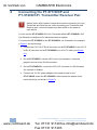
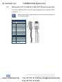
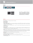
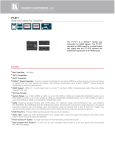
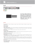
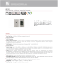
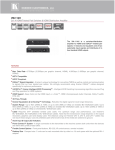
im Vertrieb von
CAMBOARD Electronics
K R A ME R E LE CT R O N IC S L T D .
USER MANUAL
MODELS:
PT-571HDCP
DVI Line Transmitter
PT-572HDCP+
DVI Line Receiver
P/N: 2900-000689 Rev 6
www.camboard.de
Tel. 07131 [email protected]
Fax 07131 911203
im Vertrieb von
www.camboard.de
CAMBOARD Electronics
Tel. 07131 [email protected]
Fax 07131 911203
im Vertrieb von
CAMBOARD Electronics
Contents
1
Introduction
1
2
2.1
2.2
Getting Started
Achieving the Best Performance
Accessory to Medical Equipment (IEC 60601-1)
2
2
3
3
3.1
3.2
3.3
Overview
Using Twisted Pair Cable
About the Power Connect™ Feature
About HDCP
4
5
5
5
4
Defining the PT-571HDCP DVI Line Transmitter
6
5
Defining the PT-572HDCP+ DVI Line Receiver
7
6
6.1
Connecting the PT-571HDCP and PT-572HDCP+ Transmitter Receiver Pair
Wiring the CAT 5 LINE IN / LINE OUT RJ-45 Connectors
8
10
7
Technical Specifications
11
Figures
Figure 1: PT-571HDCP DVI Line Transmitter
Figure 2: PT-572HDCP+ DVI Line Receiver
Figure 3: Connecting the PT-571HDCP/PT-572HDCP+ Transmitter/Receiver Pair
Figure 4: CAT 5 PINOUT
6
7
9
10
PT-571HDCP/PT-572HDCP+ – Contents
i
U
U
U
U
U
U
U
U
www.camboard.de
Tel. 07131 [email protected]
Fax 07131 911203
im Vertrieb von
1
CAMBOARD Electronics
Introduction
Welcome to Kramer Electronics! Since 1981, Kramer Electronics has been
providing a world of unique, creative, and affordable solutions to the vast range of
problems that confront the video, audio, presentation, and broadcasting
professional on a daily basis. In recent years, we have redesigned and upgraded
most of our line, making the best even better!
Our 1,000-plus different models now appear in 11 groups that are clearly defined
by function: GROUP 1: Distribution Amplifiers; GROUP 2: Switchers and Routers;
GROUP 3: Control Systems; GROUP 4: Format/Standards Converters; GROUP
5: Range Extenders and Repeaters; GROUP 6: Specialty AV Products; GROUP
7: Scan Converters and Scalers; GROUP 8: Cables and Connectors; GROUP 9:
Room Connectivity; GROUP 10: Accessories and Rack Adapters, and GROUP
11: Sierra Products.
Congratulations on purchasing your Kramer PT-571HDCP and PT-572HDCP+
transmitter/receiver pair, which is ideal for the following typical applications:
•
Boardrooms, conference rooms and training rooms
•
Presentation systems
•
Signal distribution and home theater
•
Range extender for medical equipment
!
You must use Shielded Twisted Pair (STP) cabling with the
PT-571HDCP and PT-572HDCP+.
!
Use only a straight pin-to-pin cable with RJ-45 connectors that
meet the EIA /TIA 568B standard. Failure to do so may result in
damage to the device(s).
PT-571HDCP/PT-572HDCP+ - Introduction
www.camboard.de
1
Tel. 07131 [email protected]
Fax 07131 911203
im Vertrieb von
2
CAMBOARD Electronics
Getting Started
We recommend that you:
•
Unpack the equipment carefully and save the original box and packaging
materials for possible future shipment
2.1
•
Review the contents of this user manual
•
Use Kramer high performance high resolution cables
Achieving the Best Performance
To achieve the best performance:
•
Use only good quality connection cables to avoid interference, deterioration
in signal quality due to poor matching, and elevated noise levels (often
associated with low quality cables)
•
Do not secure the cables in tight bundles or roll the slack into tight coils
•
Avoid interference from neighboring electrical appliances that may adversely
influence signal quality
•
Position your Kramer PT-571HDCP and PT-572HDCP+ transmitter/receiver
pair away from moisture, excessive sunlight and dust
!
i
Caution:
No operator serviceable parts inside the unit
Warning:
Use only the Kramer Electronics input power wall
adapter that is provided with the unit
Warning:
Disconnect the power and unplug the unit from the
wall before installing
Go to http://www.kramerelectronics.com to check for up-to-date user
manuals, application programs, and to check if firmware upgrades
are available (where appropriate).
2
www.camboard.de
PT-571HDCP/PT-572HDCP+ - Getting Started
Tel. 07131 [email protected]
Fax 07131 911203
im Vertrieb von
2.2
CAMBOARD Electronics
Accessory to Medical Equipment (IEC 60601-1-2)
In the modern medical environment remote access is essential, for example, to
transfer clinical data between doctors and to train to medical students. The
PT-571HDCP/PT-572HDCP+ pair is certified according to the IEC 60601-1-2,
Clause 2.1.3, Medical Electrical Equipment, Part 1: General Requirements for
Emc standard which is required when accessory devices are used at locations
where medical personnel and patients are present.
The PT-571HDCP/PT-572HDCP+ pair constitutes an optional component that can
be considered necessary and suitable as part of medical equipment or for use as
part of a medical system to provide real time simultaneous video feeds to those
present at the local medical environment and at remote locations. In this
environment, the PT-571HDCP/PT-572HDCP+ can be added to the system ONLY
if the connecting equipment has been evaluated and meets the IEC 60601-1-2
Emc standards. Note, that when attaching accessory devices to a digital or analog
interface, they must comply with the IEC standard for which they are used: for
medical equipment (IEC 60601-1-2), data processing equipment (IEC 60950) and
electromagnetic compatibility (IEC 61000-1).
PT-571HDCP/PT-572HDCP+ - Getting Started
www.camboard.de
3
Tel. 07131 [email protected]
Fax 07131 911203
im Vertrieb von
3
CAMBOARD Electronics
Overview
The PT-571HDCP is a DGKat™ twisted pair transmitter for DVI signals. The
PT-571HDCP converts a DVI signal to a single twisted pair signal and the
PT-572HDCP+ converts the twisted pair signal back to a DVI signal.
The DVI Line Transmitter/Receiver system features:
•
Maximum data rate/bandwidth up to 1.65Gbps, WUXGA, 1920x1080p
•
HDTV compatibility and HDCP compliance
•
Medical equipment compliance
•
EDID PassThru that passes EDID signals between the source and display
•
3D pass-through
•
System Range – Up to 90m (295ft) at 1080i, or up to 30m (98ft) at 1080p on
shielded BC-DGKat524 cable; 90m (295ft) at 1080i, or up to 70m (230ft) at
1080p on shielded BC-DGKat623 cable; 100m (330ft) at 1080i or up to 90m
(295ft) at 1080p on shielded BC-DGKat7a23 cable
Note that the transmission range depends on the signal resolution, graphics card and
display used. The distance using non-Kramer CAT 5, CAT 6 and CAT 7a cables may
not reach these ranges
•
DGKat™ Signal Integration – Kramer’s unique technology for converting
TMDS as well as control and communication to signals that run over twisted
pair cables
•
Power Connect™ that feeds 12V DC over the CAT 5 cable from transmitter
to receiver (see Section 3.2)
•
Ultra-Compact Pico TOOLS™ – 4 units can be rack mounted side−by−side
in a 1U rack space with the optional RK−4PT rack adapter.
i
Use only shielded cable where both ends of the shield are soldered
to ground to eliminate ESD interface.
4
www.camboard.de
PT-571HDCP/PT-572HDCP+ - Overview
Tel. 07131 [email protected]
Fax 07131 911203
im Vertrieb von
3.1
CAMBOARD Electronics
Using Twisted Pair Cable
Kramer engineers have developed special twisted pair cables to best match our
digital twisted pair products; the Kramer: BC-DGKat524 (CAT 5 24 AWG), the
Kramer: BC-DGKat623 (CAT 6 23 AWG cable), and the Kramer: BC-DGKat7a23
(CAT 7a 23 AWG cable). These specially built cables significantly outperform
regular CAT 5/CAT 6/CAT 7a cables.
3.2
About the Power Connect™ Feature
The Power Connect™ feature here means that only one unit in a system, the
transmitter or receiver, needs to be connected to a power source when the
devices are within 90m (270ft) of each other. The Power Connect™ feature
applies as long as the cable can carry power and the distance does not exceed
90m on standard CAT 5 cable. For longer distances, heavy gauge cable should be
used (CAT 5 cable is still suitable for the video/audio transmission, but not for
feeding the power at these distances).
3.3
About HDCP
The High-Bandwidth Digital Content Protection (HDCP) standard developed by
Intel, protects digital video and audio signals transmitted over DVI or HDMI
connections between two HDCP-enabled devices to eliminate the reproduction of
copyrighted material. To protect copyright holders (such as movie studios) from
having their programs copied and shared, the HDCP standard provides for the
secure and encrypted transmission of digital signals.
PT-571HDCP/PT-572HDCP+ - Overview
www.camboard.de
5
Tel. 07131 [email protected]
Fax 07131 911203
im Vertrieb von
4
CAMBOARD Electronics
Defining the PT-571HDCP DVI Line
Transmitter
The Kramer Pico TOOLS PT-571HDCP DVI Line Transmitter receives a DVI
signal, encodes it, and transmits it over a CAT 5 cable to the PT-572HDCP+. The
PT-571HDCP has:
•
A DVI input connector
•
An RJ-45 CAT 5 output connector
•
One power status LED
Figure 1: PT-571HDCP DVI Line Transmitter
#
1
12V DC
Feature
Function
+12V DC connector for powering the unit
2
DVI IN Connector
Connect to the DVI source
3
OUT RJ-45 Connector
Connect to the IN RJ-45 connector on the PT-572HDCP+
4
ON LED
Lights only when the machine is powered (whether directly
from the power adapter or via the PT-572HDCP+) and an
input is connected
If no input is connected the unit invokes the power save
mode automatically turning off the power
6
PT-571HDCP/PT-572HDCP+ - Defining the PT-571HDCP DVI Line Transmitter
www.camboard.de
Tel. 07131 [email protected]
Fax 07131 911203
im Vertrieb von
5
CAMBOARD Electronics
Defining the PT-572HDCP+ DVI Line
Receiver
The Kramer Pico TOOLS PT-572HDCP+ DVI Line Receiver receives an encoded
signal over a CAT 5 cable transmitted from the PT-571HDCP, decodes it, and
converts it to a DVI output.
The PT-572HDCP+ has:
•
A DVI output connector
•
An RJ-45 CAT 5 input connector
•
One power status LED
Figure 2: PT-572HDCP+ DVI Line Receiver
#
1
12V DC
Feature
Function
+12V DC connector for powering the unit
2
DVI OUT Connector
Connect to the DVI acceptor
3
IN RJ-45 Connector
Connect to the OUT RJ-45 connector on the PT-571HDCP
4
ON LED
Lights red when receiving power only, orange when output
and power are attached, and yellow when both an active
input and output are attached
PT-571HDCP/PT-572HDCP+ - Defining the PT-572HDCP+ DVI Line Receiver
www.camboard.de
7
Tel. 07131 [email protected]
Fax 07131 911203
im Vertrieb von
6
CAMBOARD Electronics
Connecting the PT-571HDCP and
PT-572HDCP+ Transmitter Receiver Pair
!
Always switch off the power to each device before connecting it to your
Transmitter and Receiver pair. After connecting your Transmitter and
Receiver pair, connect the power and then switch on the power to
each device.
You can use the PT-571HDCP DVI Line Transmitter with the PT-572HDCP+ DVI
Line Receiver to configure a DVI transmitter/receiver system.
To connect the PT-571HDCP to the PT-572HDCP+, as illustrated in the example
in Figure 3, do the following:
1. Connect the CAT 5 OUT RJ-45 connector on the PT-571HDCP to the CAT 5
IN RJ-45 connector on the PT-572HDCP+ via a CAT 5 cable (see Section
6.1).
2. On the PT-571HDCP, connect a DVI source (for example, a computer
graphics source) to the DVI IN connector.
3. On the PT-572HDCP+, connect the DVI OUT connector to a DVI acceptor
(for example, a display).
4. Connect the 12V DC power adapter to the power socket on the
PT-571HDCP and/or the PT-572HDCP+ and connect the adapter to the
mains electricity (not shown in Figure 3).
8
www.camboard.de
PT-571HDCP/PT-572HDCP+ - Connecting the PT-571HDCP and
PT-572HDCP+ Transmitter Receiver Pair
Tel. 07131 [email protected]
Fax 07131 911203
im Vertrieb von
CAMBOARD Electronics
Figure 3: Connecting the PT-571HDCP/PT-572HDCP+ Transmitter/Receiver Pair
PT-571HDCP/PT-572HDCP+ - Connecting the PT-571HDCP and
PT-572HDCP+ Transmitter Receiver Pair
www.camboard.de
9
Tel. 07131 [email protected]
Fax 07131 911203
im Vertrieb von
6.1
CAMBOARD Electronics
Wiring the CAT 5 LINE IN / LINE OUT RJ-45 Connectors
This section defines the CAT 5 pinout, using a straight pin-to-pin cable with RJ-45
connectors.
i
Note, that the cable Ground shielding must be connected / soldered to
the connector shield.
Figure 4: CAT 5 PINOUT
EIA /TIA 568B
PIN
1
Wire Color
Orange / White
2
Orange
3
Green / White
4
Blue
5
Blue / White
6
Green
7
Brown / White
8
Brown
Pair 1
4 and 5
Pair 2
1 and 2
Pair 3
3 and 6
Pair 4
7 and 8
10
www.camboard.de
PT-571HDCP/PT-572HDCP+ - Connecting the PT-571HDCP and
PT-572HDCP+ Transmitter Receiver Pair
Tel. 07131 [email protected]
Fax 07131 911203
im Vertrieb von
7
CAMBOARD Electronics
Technical Specifications
PT-571HDCP
PT-572HDCP+
INPUTS:
1 RJ-45 connector
1 DVI, 1.2Vpp on a DVI
Molex 24pin female
connector; DDC signal 5Vpp
(TTL)
OUTPUTS:
1 RJ-45 connector
BANDWIDTH:
Supports up to 1.65Gbps bandwidth per graphic channel
OPERATING TEMPERATURE:
0° to +55°C (32° to 131°F)
STORAGE TEMPERATURE:
-45° to +72°C (-49° to 162°F)
1 DVI, 1.2Vpp on a DVI
Molex 24-pin female
connector; DDC signal 5Vpp
(TTL)
HUMIDITY:
10% to 90%, RHL non-condensing
POWER SOURCE:
12V DC, 250mA
DIMENSIONS:
6.2cm x 5.2cm x 2.4cm (2.4" x 2.1" x 1") W, D, H
WEIGHT:
0.14kg (0.3lbs)
ACCESSORIES:
OPTIONS:
Power supply, mounting brackets
19” RK-4PT rack adapter, Kramer DVI cables and
BC-DGKat524 (CAT 5 24 AWG), BC-DGKat623 (CAT 6 23
AWG) and BC-DGKat7a23 (CAT 7a 23 AWG) cables
12V DC, 250mA
Specifications are subject to change without notice
Go to our Web site at http://www.kramerelectronics.com to access the list of resolutions
PT-571HDCP/PT-572HDCP+ - Technical Specifications
www.camboard.de
11
Tel. 07131 [email protected]
Fax 07131 911203
im Vertrieb von
12
www.camboard.de
CAMBOARD Electronics
PT-571HDCP/PT-572HDCP+ - Technical Specifications
Tel. 07131 [email protected]
Fax 07131 911203
im Vertrieb von
CAMBOARD Electronics
For the latest information on our products and a list of Kramer distributors,
visit our Web site where updates to this user manual may be found.
We welcome your questions, comments, and feedback.
Web site: www.kramerelectronics.com
E-mail: [email protected]
!
SAFETY WARNING
Disconnect the unit from the power
supply before opening and servicing
PN: 2900- 000689
www.camboard.de
Rev: 6
Tel. 07131 [email protected]
Fax 07131 911203