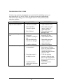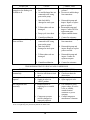
1
TR-602/TR-600 ARCH PUMP Version 1.1 Operator’s Manual Table of Contents • • • • • Introduction System Components Installation & Operations Start Up Well Development Technique Decontamination Troubleshooting Maintenance p.2 p.3 p.4,5 p.6 p.7 p.8 p.9 p.10 1998 Durham Geo-Enterprises, Inc. 2175 West Park Court • PO Box 870907 Stone Mountain, GA 30087 USA Telephone 770.465.7557 • Fax 770.465.7447 Email: [email protected] Printed in the USA INTRODUCTION The Arch Pump System is designed for well development. The Arch pump can pump slurries of silt and fine sand, a unique design feature which gives it a wide range of applications. The pump disassembles easily for decontamination between wells. A key piece in the pump’s design has an arched shape, which gives the Arch pump its name. This user’s manual introduces the Arch pump and provides step-by-step guidelines for successful operation. Read this information carefully before using the pump and keep the manual handy for field reference or review by first-time users. Should you have any questions about using your Arch Pump, please call Durham GeoEnterprises at: 1-800-837-0864 or 770-465-7557 2 SYSTEM COMPONENTS This section introduces the system components to the first-time user. The Arch Pump system consists of two basic components: the Arch Pump and the controller. ARCH PUMP The Arch pump has a rigid outer shell and an inner assembly consisting of a discharge tube, discharge check valve, and inlet check ball and arch seat. The check valve permits one-way flow upward through the discharge tube. There are labeled ports on top of the pump for connection of the discharge hose and supply air hose. The Arch pump is constructed of durable 304 stainless steel with Teflon seals at either end. Inlet check balls of Teflon, Buna-N and Viton are available. CONTROLLER The controller governs the system operation by supplying a timed, cyclic air pulse to the Arch pump. As with any pneumatically powered device, the use of a clean and dry air source is essential to proper operation of the controller. A minimum of 5 micron-filtered air is required. The unit is designed for working pressures of 40 to 125 psi. Pressures in excess of 125 psi will damage the controller. 3 INSTALLATION AND OPERATIONS GENERAL NOTES This selection addresses the installation, start-up, and operation of the Arch well development pump. The following general notes apply to use of the pump. 1. The Arch pump is intended primarily for use in small diameter (2”to 6”) wells. When used in larger wells, take care to keep the pump suspended and vertical. 2. Position the controller such that it will remain relatively clean and dry. The unit is designed for outdoor use; however, avoid locations where the controller may be submerged in water, as this will cause damage. Keep the lid closed while the unit is running. Locating the controller closer to the well head will improve pump performance. 3. In installations where the well is deep and/or the controller is far from the well head, use the quick exhaust accessory to quickly depressurize the empty pump. The quick exhaust permits air to be exhausted quickly at the well rather than exhausting through the controller. 4 INSTALLATION PROCEDURES The following simple steps prepare the Arch pump for installation into the well. Prior to installation, characteristics of the well should be known. Measure the depth of the well, and check for excessive silting (this can be accomplished easily with a hand bailer). The presence of a silted-in zone will require particular well development techniques. 1. To begin, the Arch pump should be fully assembled. 2. Determine the required length of air and discharge lines. Allow adequate length to reach easily from the pump to the controller and to the discharge location. The hose or tubing must be 3/8” I.D. and rated for the applied pressure. Polyethylene tubing is a commonly used material. 3. Attach the hoses to the ports on top of the Arch pump, taking care to attach the proper hose to the proper fitting (the ports are labeled). Seal the connections with good quality stainless steel clamps. 4. Connect the air hose to the output port of the controller and seal with a 3/8” hose barb and clamp. 5. Secure the discharge hose to the designated discharge location. An unsecured discharge hose is a safety hazard. 6. Durham Geo recommends that a safety rope or cable be attached to the discharge end of the Arch pump and secured to the well head. 7. Once secured, carefully lower the Arch pump into the well. Do not drop the pump to the bottom of the well initially, as the inlet may become clogged with silt. It is suggested that at first the pump be suspended above the well bottom or silted-in zone. 5 SYSTEM START-UP The remaining steps involve pressurizing the system and setting the controls to achieve the desired pumping rate. The controller settings for most efficient pump performance will vary with hose length, well depth, operating pressure, and the viscosity of the material being pumped. 1. Attach the air supply (compressor or bottled gas) to the input port of the controller. 2. Adjust the supply air pressure. An operating pressure of 60 psi is sufficient for most applications. As a rule of thumb, the minimum operating pressure (in psi) = the total head in feet. 2 HT where HT equals The operating pressure must be between 40 and 125 psi, the working range of the controller. 3. Adjust the controller settings. Turning the knobs clockwise increases the time; turning counter-clockwise decreases the time. The interval 30 to 0 is a nonfunctional region. Initially, turn the “off” timer clockwise to a setting of 15 and the “on” timer clockwise to 5. 4. Open the air supply valve to energize the Arch Pump system. Allow the system to operate for several cycles. 5. The “on” time will be optimized first. As the system pumps, observe the discharge hose. Incrementally increase the “on” time between cycles, letting the system respond to each increase. Continue until air is just discharged (the discharge hose will “chatter” and jump when expelling air). Now decrease the “on” time slightly until no air is discharged. 6. The “off” time is then optimized in a similar fashion. Observe the discharge hose during continued cycling of the pump. Incrementally decrease the “off” time between cycles until air is just discharged; then increase the “off” time slightly. The controller is now optimized for the existing set of variables, allowing no waste of air or time in pump operation. We note that further increase in “on” time, beyond optimum, will not increase well yield. 6 WELL DEVELOPMENT TECHNIQUE The condition of the well should be investigated prior to installation of the Arch well development pump. A hand bailer can be used to check for excessive silting in the bottom of the well. Silting, the settlement of fine-grained materials often occurs due to passage of in-situ soils through the sand pack and well screen and/or the introduction of slurried muds during well drilling. In many cases, there may be a zone or “plug” of solids at the base of the well. It is important that the Arch pump not be dropped into the silted-in zone or permitted t sit on the bottom of the well. This would allow the silty material to clog the inlet of the pump. Instead, it is suggested that the pump be suspended about 2’ above the well bottom or silted zone during system start-up. Once the controls have been properly set, well development can proceed. The Arch pump can remove silts and fine sands, provided they are in suspension. A “surging” technique will disturb the settled material, causing the silt to become suspended. Surging involves raising and lowering the cycling pump near the silted in zone. The effectiveness of surging can be observed in the pump discharge, which will become noticeably entrained with mud and/or silt and sand. Note: In cases where sands are excessive, the use of a Buna-N check ball will improve performance. 7 DECONTAMINATION The Arch pump is commonly used to develop several wells in a new well field. The pump is typically decontaminated between wells to minimize potential for crosscontamination. The method and level of decontamination required depends on sitespecific characteristics such as the environmental sensitivity of the site, sampling protocol, product contaminant types, and other factors. 1. Raise the pump above the water level within the well and allow it to cycle a few times to empty. When the pump has emptied, the discharge line will pass air. Turn off the air supply and disconnect the air line from the controller. Lift the pump out of the well. This procedure avoids spillage and possible water damage to the controller. 2. After removing the pump from the well, disconnect the air and discharge lines. 3. Grasp the pump firmly at both ends and, using counterclockwise rotation, unscrew the bottom end cap from the pump body. If the cap cannot be unscrewed by hand, use only the spanner wrenches supplied with the pump. Do not use a pipe wrench or pliers; this may damage the pump and void the warranty. 4. Slide the pump body off and remove the inner discharge tube assembly. 5. Decontaminate the equipment. Methods will depend on the level of decontamination required for the site. Methods include using appropriately sized brushes and a cleansing solution of Alconox or similar agent, the use of a steam cleaner, etc. Depending on the level of decontamination required for the site, the pump can possibly be cleaned without disassembly. Prepare a cleansing solution in a drum or other vessel with suitable volume. Immerse the assembled Arch pump and cycle, allowing the solution to recirculate through the system. Prior to reassembly of the pump, inspect the Teflon seal washers and the check ball for tears and pitting. These and other signs of wear will negatively affect pump performance. Replace these elements as needed. During reassembly, the end caps should be hand tightened with the wrenches supplied. Take care not to over tighten them; this will increase wear on the seals and result in leakage during operation. Also, take care not to cross-thread the bottom end cap during reassembly. Avoid careless handling that could deform the pump body and result in leakage. 8 TROUBLESHOOTING GUIDE If you have any questions concerning the use or operation of the Arch Pump system, you may call us toll-free at 1-800-837-0864. We suggest you check the Troubleshooting Chart below before calling; you can often diagnose and solve minor problems quickly using these guidelines. SYMPTOM Arch pump discharges air only or a water/air mixture. CAUSE a. “On” time is too long. b. “Off” time is too short. c. Inlet check ball is damaged or pitted. d. Inlet is blocked. Arch pump discharges air only. Controller does not cycle. a. Well has been dewatered. b. Controller is cycling too fast. c. Inlet check ball and/or end seals are damaged. d. Controller malfunction. a. Air source is restricted or contaminated. b. Operating pressure is too high or too low. c. Controller has been submerged or otherwise damaged. 9 CORRECTION a. Adjust controller timers. b. Adjust controller timers. c. Disassemble pump and inspect. Contact for replacement parts. d. Disassemble pump and thoroughly clean. a. Reduce pumping rare by increasing “off” time. b. Adjust controller timers. c. Disassemble pump and inspect. Contact for replacement parts. d. Contact for assistance. a. Check for and straighten kinks in hoses. Check air source for water condensate. If present, disconnect controller and purge air lines and service filter. b. Verify that operating pressure is within the range 40 to 125 psi. If upper limit has been exceeded, unit may be damaged. c. Contact for repair or replacement. SYMPTOM Controller cycles, but Arch pump does not discharge air or fluids at all. CAUSE a. Supply air pressure is too low. b. Air and discharge lines are connected to the wrong ports on the pump. CORRECTION a. Adjust operating air pressure. b. Reverse air and discharge line connections. c. Inlet check ball is damaged or stuck open. c. Disassemble pump and inspect. Repair or replace parts as needed. d. Disassemble pump and inspect. Contact DGE for replacement parts. e. Adjust controller timers. d. Teflon washer seals are damaged. e. Pump cycle is too short. Air/water mixture discharged from well bore. f. Controller malfunction. a. Air and discharge lines are connected to the wrong ports on the pump. b. Inlet check ball is damaged or stuck open. f. Contact for assistance. a. Reverse air and discharge line connections. c. Teflon washer seals are damaged. c. Disassemble pump and inspect. Contact for replacement parts. d. Controller malfunction. d. Contact for assistance. b. Disassemble pump and inspect. Repair or replace parts as needed. TROUBLESHOOTING IF USING AN AIR COMPRESSOR SYMPTOM CAUSE CORRECTION Air compressor runs a. Air is leaking from line(s). a. Check lines for air leaks. continuously. b. Receiver auto-drain is stuck b. Check auto-drain for open. obstructions. Air compressor does not a. Electrical service is faulty. a. Inspect electrical service. operate. b. Supply air valve is in b. Open supply air valve. “closed” position. Air compressor runs a. Electrical service is a. Use voltmeter to verify erratically. supplying low or variable proper voltage. If service voltage. is low or variable, consult electrical contractor or power company. b. Compressor pressure b. Consult compressor switch is damaged or manufacturer’s literature. improperly adjusted. Refer to the air compressor manufacturer’s literature for additional information. Note: Overtightening will permanently deform the Teflon seals. 10 CARE INFORMATION Maintenance The Arch Pump system is durable and has been designed to withstand the rigors of its intended field use. With proper operation, in accordance with this manual, little maintenance is required to ensure continued high performance. The system should be stored in a dry location, out of direct sunlight. The Arch pump should be inspected regularly for signs of wear. Note the condition of the Teflon seals and check ball; these should be free of tears and pitting. The need for maintenance of the controller depends directly up on the way it is used. The controller must be supplied with air that is clean and relatively dry. Also, the controller must not be submerged. If these requirements are met, the controller will require no special maintenance. Maintenance instructions for the air compressor, if used, are detailed in the manufacturer’s Operations Manual. In general, proper maintenance includes regular oil changes and periodic inspection of the inlet air filter, belts, and other parts for signs of wear. Manufactured by: DURHAM GEO-ENTERPRISES Durham Geo-Enterprises, Inc. 2175 West Park Court Stone Mountain, GA 30087 PH: 770-465-7557 • 800-837-0864 Fax: 770-465-7447 11